Research into the geometry of the delimbing head
of cutting knives
J. Mikleš
Department of Forest and Mobile Technologies, Faculty of Environmental
and Manufacturing Technologies, Technical University in Zvolen, Slovak Republic
Abstract
Mikleš J., 2012. Research into the geometry of the delimbing head of cutting knives. Res. Agr. Eng., 59: 29–34.
Limbing with a wedge tool as a chipless operation is accompanied by a large deformation of wood in the cutting plane, i.e. at the spot of contact with the tool face as well as in the zone adjacent to this plane. The theory of chipless cutting says that the resistance of wood fibers to deformation is particularly the main component of resistance to the tool penetration into wood. The friction component (resistance component) on the tool surface is a function describing resistance to fibre deformation, its magnitude depending upon the value of friction coefficient. The magnitude of cutting force acting in a direction of the velocity vector is a resultant of all resistance components acting on the particular parts of the tool which make up the cutting profile (face, back edge, cutting edge). In the presented paper force analysis is presented for the operation of a delimber. The objective of these experimental tests was to minimize energy requirement for limbing through determination of optimum geometry of delimbers while providing for the good quality of the limbing.
Keywords: forest machinery; delimber; delimbing tool; tool geometry
Supported by the Scientific Grant Agency VEGA of the Ministry of Education of the Slovak Republic and the Slovak Academy of Sciences, Grant No. 1/0048/09.
The paper deals with the analysis of force applica-tion on a delimbing tool and with the determina-tion of tangential and normal resultant force act-ing on the tool. In order to minimize the energy demand for delimbing, the experiments were car-ried out to optimize the geometry of delimbing tools while assuring the quality of delimbing. The result is the minimal cutting resistance in the pro-cess of delimbing and a reduced demand for the output of driving unit. The tests were carried out on a special stand at the Department of Forest and Mobile Technique, Faculty of Environmental and Manufacturing Technologies, Technical Univer-sity in Zvolen, Slovak Republic. There were tested 15 knives of different geometry. On the basis of tests the tool with an optimal geometry for delimb-ing was chosen.
Problems and theoretical analysis
Delimbing with a wedge tool as a chipless op-eration is accompanied by a large deformation of wood in the cutting plane, i.e. at the spot of contact with the tool face as well as in the zone adjacent to this plane. It is well known from the theory of chip-less cutting that the main component of resistance to the tool penetration into wood is the resistance of wood fibres to deformation. The friction com-ponent (resistance comcom-ponent) on the tool surface is function describing the resistance to fiber defor-mation; its magnitude depends upon the value of coefficient of friction.
tool, and making up the cutting profile (face, back edge – cutting edge).
The published works (Prelovskij 1975; Radocha et al. 1986; Golod 1987; Sokolov, Leonov 1987; Voronycyn, Gugelev 1989; MacDonald 1993; Horváth 2003; Mikleš 2009) dealing with the lem of delimbing do not give an answer to this prob-lem from the viewpoint of minimization the cutting resistance in delimbing with delimbing knife head.
Force analysis of the work of delimbing tool
For determination of forces acting on the work-ing surface of delimbwork-ing knife, which is in contact with wood, in accordance with Prelovskij (1975) methods, we can divide the knife into series of zones (i-sections) and find the resultants of unit pressures on the knife surface Ni, separately for each zone.
Working surface of the knife can be divided into eight parts (Fig. 1): KL – face of knife, LS – puting front section of cutting edge, SA – com-puting back section of cutting edge, AB – negative back section of knife, BC – section connecting the negative part of back (AB) with supporting surface of knife (CD), CD – supporting section of the back knife, DE – section connecting part of the back knife surface (CD) with the positive part (surface) of back knife, EF – positive part of back knife.
Cutting plane MN divides the working surface of knife into the front and back part of knife. The front part of knife consists of the front area KL and the
front section of the edge LM. The back part of knife MABCDEF consists of six sections. The section of the back area AB with negative cutting angle δ4 is at the same time the back angle α.
Cutting plane MA, which is between cutting MN and negative back plane is the back edge.
In computation it is more convenient not to con-sider the geometric surface of edge – the section LM and MA, but the computing cutting edge sur-face – sections LS and SA.
The surface of cutting edge is formed by ρ with the curvature centroid at the point 0. The plane OS, which passes through the cutting edge curvature centroid, the point 0, divides LSA into front and back part. For simplification of computations, the direction of longitudinal axis of delimbed branch can be taken as the direction of grains.
The front part of the cutting edge is the edge surface, located between the front of knife and the plane which passes through the curvature centroid perpendicular to grain direction.
Back part of the cutting edge is an edge surface located between the negative back area and the plane passing through the curvature centroid per-pendicular to grain direction.
Supporting part of delimbing back is the section of knife back, which touches the surface of stem.
The positive back area is a section of the back with positive angle of the back.
[image:2.595.66.358.86.332.2]the support part of the back, where it is in contact with the stem.
The length of the supporting section (surface) of the knife CD is determined from the condition of allowed unit pressure of the knife on stem surface. If the knife does not have supporting area or its section is small (minimum length), simultaneously with delimbing also comes to a partial debarking.
Each section of working surface of the knife refers to a resultant of specific pressures: N1 – acts on the front of knife; N2– acts on the computed front edge area; Ni– on i section of the working surface of knife.
Friction forces acting on wood in the cutting pro-cess for corresponding working zones of the knife will equal to:
Ti= µi×Ni (1)
where:
μi – coefficient of friction between wood and i section of working surface of the knife
Ti – friction force
When we resolve the resultant of specific pres-sures into each section of knife Ni and the friction force Ti into the components FRi, parallel to the cutting plane MN and on the normal components to this plane Qi, then we get:
FRi= ±Ni×sinδi
F''Ri = + Ti×cosδi ± μi× Ni×cosδi from this follows that:
FRi = F'Ri + F''Ri = Ni(± sinδi ± μi×cosδi)
Q'i = ± Ni×cosδi (2)
Q''i = + Ti×sinδi ± μi× Ni×sinδi from this follows that:
Qi = Q'i + Q''i = Ni(± cosδi± μi × sinδi) (3) Tangential cutting force FR will equal to the sum of its components in each zones of the knife:
FR= FRi k=1
n
∑
(4)Normal force Q which acts on the wood also equals to the algebraic sum of its components:
Q= Qii
k=1 n
∑
(5)where:
n – number of sections (zones), into which the working surface of the knife is divided, which is in contact with wood (in the observed case n = 8)
In assessing the optimum geometry the cutting force variable (FR) served as a criterion.
MATERIAL AND METHODS
For solution of these problems the special ap-paratus was built which enables to observe the process of cutting in laboratory conditions and to measure the cutting forces affecting the energy in-tensity in the process of cutting. The stand has a frame construction, the drive of the tool – delimb-ing knife is provided by rectilinear hydraulic motor. The knife is interchangeable, it moves in the guide against a firmly gripped sample, which is a small log with branches.
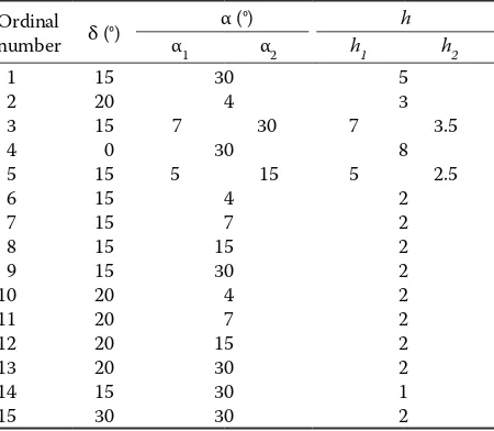
For finding out the forces ratio in cutting spruce was used as a basic species because its cutting re-sistance seems to be maximum from those taking into account for machine delimbing. Cutting re-sistance of branches was measured with freshly cut wood with a moisture content of 40% up to 70%. With respect to branch diversity, prior to each ex-perimental operation (by cutting) the branch di-ameter was measured in the cutting plane (outside-bark and inside-(outside-bark), inclination angle of its axis from normal line to the vector of cutting speed, and the branch setting was described if irregular. The tools with geometric parameters given in Table 1 were used in the course of cutting. Their geometry is obvious from Fig. 2, the cutting speed was 4 cm/s.
[image:3.595.306.531.545.741.2]The task lays in determining optimal geometry of the tool. Under the same cutting conditions the
Table 1. Tools used for the tests
Ordinal number δ (°)
α (°) h
α1 α2 h1 h2
1 2 3 4 5 6 7 8 9 10 11 12 13 14 15 15 20 15 0 15 15 15 15 15 20 20 20 20 15 30 30 4 7 30
30 5 15
4 7 15 30 4 7 15 30 30 30 5 3 7 3.5
8 5 2.5
2 2 2 2 2 2 2 2 1 2
magnitude of max. cutting force (or the measured cutting force) was determined.
The max. magnitude of cutting force FRMAX, as it is known from literature according to Prelovskij (1975), Golod (1987) – and it is also confirmed by performed tests – is directly proportional to square diameter of the cut branch D outside bark.
FRMAX = a1 × D2 (N)
where:
a1– coefficient of proportionality which depends on the parameters of tool, tree species and the angle of set-ting of the branches
This relation can be expressed, so that FRMAX
is directly proportional to the cutting area of the branch S:
FR
MAX = k × S where:
k = FspMAX– coefficient of proportionality responds to max. cutting force, which includes the influence of geometric characteristics of the tool (N/mm2)
Max. cutting force FspMAX (N/mm2) from the above given reasons was chosen as a parameter for the choice of optimum tool geometry and it is given by the quotient of maximum cutting force FRMAX
and by the diameter of cut sample – cutting area.
RESULTS AND DISCUSSION
Effect of the cutting angle of the cutting tool on the magnitude
of maximum cutting force
[image:4.595.94.253.88.277.2] [image:4.595.67.286.423.727.2]The effect of the cutting angle on cutting force was studied with the cutting tools No. 6 and 15 in the con-stant thickness of knife s = 15 mm and speed 4 cm/s. Fig. 2. Geometry of the cutting edge of tools
Fig. 3. Dependence of maximum cutting force on the angle
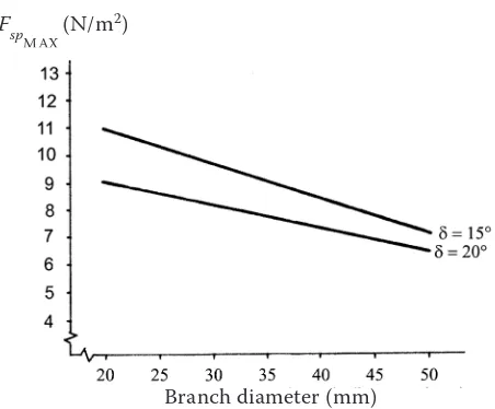
of tool cutting edge Fig. 4. Effect of the back edge angle on the magnitude of maximum cutting force with constant cutting angle δ = 20°
Branch diameter (mm) Branch diameter (mm)
FMAX (N)
Fsp
MAX (N/m 2) 13,000
12,000
11,000
10,000
9,000
8,000
7,000
6,000
5,000
4,000
[image:4.595.307.535.533.726.2]The data acquired by measuring were processed and evaluated by statistic methods. For the sake of lucid-ity in Fig. 3 only some regression curves are depicted. The best results were achieved with the angle of tool cutting edge β = 27°. In comparison with an angle of tool cutting edge e.g. β = 60° the specific cutting force with β = 27° has decreased by 5.97 N/mm2.
Effect of back edge angle of the cutting tool on the magnitude
of maximum cutting force
This effect was investigated with the cutting tools No. 6, 7, 8 and 9 and with the No. 11, 12, 13, i.e. with the cutting tools with constant thickness and the constant cutting angle.
The effect of the back edge angle on the magni-tude of maximum cutting force is depicted in Fig. 4.
From this comparison the advantage of the back edge angle α = 7° is clear. With increasing or de-creasing its magnitude it also increases the mag-nitude of cutting force up to the back edge angle α = 30°, it means that with α = 15°it decreases by 1.37 N/mm2, which is 40.88%.
From Fig. 4 it follows that the most advantageous is the back edge angle α = 4°, however this is dis-torted by the fact, that in case of the cutting tool No. 7 (α = 7°) the limbed branches were thicker than in the case of the cutting tool No. 6 (α = 4°).
With cutting tools No. 3 and No. 5 the back edge angle equals to α = α1 + α2, while with the cutting tool No. 3 good results were achieved, but the quality of delimbing was very poor. So this way of solution does not bring desired results. The effect of cutting angle on the magnitude FspMAX is shown in Fig. 5.
Utilization of the program Statgraphics (Statistical Graphics Corporation Rainbow Technologies, War-renton, USA) enabled further graphic processing of recorded values. The graph in Fig. 6 expresses the dependence of max. specific cutting forces FspMAX
on the type of cutting tool with the 30 mm branch diameter. We can state, and the graph confirms it, that the knife No. 10 has the optimal geometry.
CONCLUSION
Special feature of the cutting tools intended for limbing the branches by power method is an inevi-table connection of efficient cutting with a tracing ability of cutting tool in the process of moving along the surface of cut stem. The magnitude of energy losses is a serious factor in the choice of optimum value of the back edge angle, but it cannot be con-Fig. 5. Effect of the back edge angle on the magnitude of
maximum cutting force with constant cutting angle α = 7° Branch diameter (mm)
Fsp
MAX (N/m 2)
6.0 6.3 6.6 6.9 7.2 7.5 7.8 8.1 8.4 8.7 9.0 9.3 9.6 9.9 10.2 10.5 10.8 11.1 11.4 11.7 12.0
1 2 3 4 5 6 7 8 9 10 11 12 13 14 15
Fsp m
ax
(N
.m
m
2)
knife type Knife type
F spM
AX
(N/mm
[image:5.595.66.292.80.267.2]2 )
[image:5.595.66.529.569.764.2]sidered as a decisive one in the design of delimbers. As the studies have shown, a negative back angle α increases the deformation of wood fibres under the cutting plane, which subsequently causes growth of cutting force and energy intensity. Therefore we recommend the α = 4° angle where this effect has
not markedly shown up yet.
The experiments showed and the evaluation con-firmed that the most appropriate geometry mani-fested itself with the cutting tool No. 10 – α = 4°, δ = 20°, h = 2 mm, s = 15 mm, ρ = 0.02 mm, there-fore we recommend the manufacturers of delim-bers to use the above given geometry of the cutting tool.
References
Golod J.G., 1987. Eksperimentaľnyje issledovanije sumar-noj vnešnej nagruzki na protaskinvajuščij mechanism sučkoreznych mašin (Experimental Investigation of Cu-mulative Load Force in Pull-thru Mechanism of Delimbing Machines). Voprosy mechanizaciji lesosečanych rabot, Chimki, Trudy CNIIME: 38–45.
Horváth B., 2003. Erdészeti gépek (Forest Machinery). Budapest, Szaktudás Kiadó: 417.
MacDonald A.J., 1993. Review of mechanical delimbers in Western Canada. FERIC, Vancouver, Technical Report No. TR-93: 27.
Mikleš M., 2009. Štúdium geometrie nožov odvetvovacej hlavice (Study of geometry knives of delimbing head). Acta Facultatis Technicae, XIV: 121–129.
Prelovskij B.N., 1975. Eksperimentaľnoje issledovanije pro-ces srezanija sučjev (Experimental research of delimbing process). Chimki, Trudy CNIIME, 140: 54–61.
Radocha M., Mandalík J., Ľubek J., 1986. Biotechnické charakteristiky stromov a matematické modelovanie para-metrov zariadení na ich spracovanie (Biotechnical Char-acteristics of Trees and Mathematics Model of Equipment Parameters for Processing). Zvolen, VÚLH: 54.
Sokolov V.N., Leonov A.L., 1987. Kačestvo mašinnoj obrezki sučjev (Quality of Machine Delimbing). Voprosy mechanizacii lesosečnych rabot. Chimki, Trudy CNIIME: 46–51.
Voronycyn K.I., Gugelev S.M., 1989. Mašinnaja obrezka sučjev na lesoseke (Machine Delimbing in Forest Glade). Forest Industry, Moscow, 272.
Received for publication July 27, 2011 Accepted after corrections November 8, 2011
Corresponding author:
Ing. Juraj Mikleš, PhD., Technical University in Zvolen, Faculty of Environmental and Manufacturing Technologies, Department of Forest and Mobile Technologies, T. G. Masaryka 24, 960 53 Zvolen, Slovak Republic