Abstract — For new ways of data transmission in industrial environments we are looking for new methods to transfer more information safely in less time. A special requirement represents the transfer of data and power supply via a simple unshielded medium. Previously conducted studies should investigate point to point, point to multipoint or multipoint to multipoint connectivity. When using a multi-carrier modulation scheme for industrial data communications, the highest requirements for signal generation, transmission and data logging are needed. For this purpose, we developed a prototype based on FPGA and ARM7 technology to perform relevant test cases under real industrial conditions. The results and experiences could be used for future industry protocols, and new generations of integrated circuits.
industrial communication systems, OFDM/TDMA, multi carrier allocation, unshielded line
I. INTRODUCTION
In recent years, the need for more transmission capacity and bus participants is increasing. Industrial plants become more and more complex. The Industrial Ethernet almost reaches completely all plant levels and increases to a standard tool of industrial communication. However, there are facilities and areas in which this use is not realizable, or simply not desired.
In analyzing of current industry communications standards, it quickly becomes aware that the transfer of user data and system power over a single communications medium is hardly used. This results firstly from the history of communication systems, but also on the number of problems which appear when trying to modulate user data on an energy supply. An example is the Power Line Communication strategy. This technology is made for the consumer market and not directly useable in a harsh industrial environment. The highly variable data rates and extreme fault liability and EMC stability are main criteria for a non industrial use [1][2]. But how can we still transfer
Manuscript received July 2, 2012; revised August 6, 2012.
All Authors are employees of the Forschungs- und Transferzentrum Leipzig e.V., Wächterstr. 13, 04107 Leipzig, Germany, ([email protected], [email protected]([email protected], [email protected]([email protected], [email protected], www.ftz-leipzig.de)
this approach into industrial environment? In the past 2 years we have dealt extensively with this issue in performing a great number of tests with a variety of prototypes. A brief overview of the results concerning this issue will be given in this paper.
II. SIGNAL GENERATION
For substantial analyses, special prototypes have been developed to perform detailed tests for the use of a modified orthogonal frequency-division multiplexing (OFDM) technique in an industrial environment. The intention was to analyze which methods permit a simultaneous transmission of data and power over a simple unshielded communication medium via point to point or point-to-multipoint topology. How can we adapt the techniques of high-speed data communications and multimedia technology to the process and factory automation to meet much higher demands on data and noise immunity in industrial communication methods?
The OFDM modulation, as used for VDSL or DVB-T should be used in our tests in a modified form of signal transmission. We have chosen a modified OFDM modulation in which the carriers are organized in a time division multiple access (TDMA) scheme.
The basic concept of multi-channel transmission is to provide a high bit rated data signal into a plurality of data signals with a lower bit rate to transmit them simultaneously parallel on different sub-channels [3][4]. These data signals with lower data rates are generally less susceptible to external interference.
The idea to assign one or more carriers of each participant and mix them together as a composition of many frequencies (Fig. 1) and subsequently modulation on the energy supply is fascinating.
Multicarrier-Modulation for Process-Oriented
Real-Time Communication Techniques in
Industrial Environment
[image:1.595.305.548.509.645.2]Tobias Rudloff*, Dietmar Telschow*, Martin Flügge*, Tilo Heimbold*
So the OFDM scheme is best suitable from theory for the parallel transmission of a large number of bits. The additional multiplex method should be used to achieve an optimum utilization of the line and frequencies.
The signals which should be transmitted are converted with an inverse fast Fourier transform (IFFT) from the frequency into the time domain, and then passed to a digital-to-analog converter (DAC) of the Medium Attachment Unit (MAU) for the following signal transmission.
On receiver side, behind an analog-to-digital conversion (ADC), by using a fast Fourier transform (FFT) the individual carriers are separated from this signal mixture by a transformation from the time into the frequency domain (see Fig 2).
When using the OFDM method, the synchronization of received signals without any information about the transmitter clocking might present a problem and could be quite extensive to control. In our system tests, this should be intercepted by a training sequence of special reference symbols certain interpreted via auto-correlation. It should also briefly mentioned, that a special windowing of the received signal is performed to reach a compensation of propagation delays and signal reflections.
III. THE INFLUENCE THROUGH THE LINE
Especially the bad line shielding (unshielded two-wire line), increases the negative effects of the transmission interference through pulse and radio jammers. Because of the line antenna effect, many questions about the electromagnetic tolerance have to be discussed. Production-related asymmetries in the geometry of the cable construction favor crosstalk and radiation or the coupling of external signals.
The influence of such effects increases with higher frequencies and increase the priority of electromagnetic
compatibility problems [5]. Furthermore, it should be noted that the cable length is frequency selective.
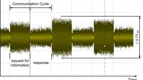
We tested in a frequency range of 1 to 7 MHz with chosen carrier frequencies at a distance of 58 kHz. A sampling frequency fA of 14.857 MHz was chosen for signal generation and data processing in the data processing unit (DPU) at a user data quantity of 20 bits per carrier. The complete data transfer time (source - sink - source) was set to 1ms. The modulated communication level was in the context of less or up to 0.5 VPP.
Figure 3 shows the voltage profile of a typical communication sequence in the time domain. Among them is illustrated the frequency spectrum of a typical transmission with a lot of used carriers. Particularly conspicuous amplitudes could be classified as external disturbances. The upper line represents the transmission current. You can see, that the sender requires more current to transmit data to all receivers than needed backwards.
IV. DATA TRANSMISSION TO THE MEDIUM
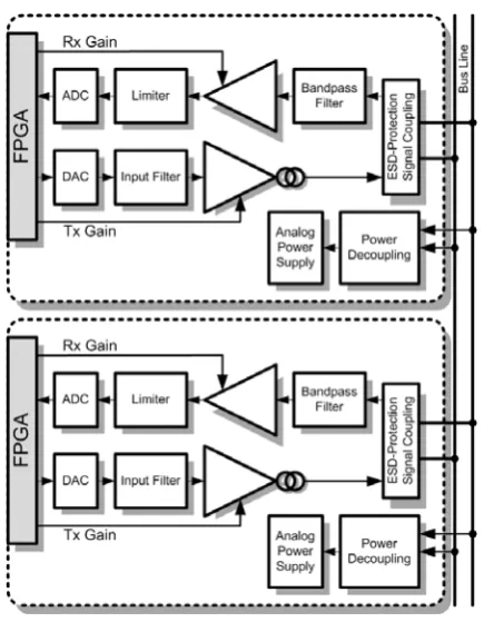
The data processing unit on both sides, transmitter and receiver, is realized as well with a Xilinx FPGA Spartan-6 XC6SLX150 and an ARM7 SAM7S256 MCU 32-bit RISC
processor. The prototyping boards could be connected with
interchangeable analog front ends (AFE) for transmitting and receiving data.
[image:2.595.306.552.87.212.2]To preserve flexibility during developing new transmission methods, a 14-Bit ADC with a sampling rate of up to 65 MSPS and a 14-Bit DAC with up to 160 MSPS are placed on each prototype. It was assumed that this 14-Bit resolution provides enough resources for all test scenarios. The Figure 4 shows the schematic structure of a prototype.
Fig. 3. FFT of a communication cycle at TX=-9dB of the transmitter
[image:2.595.62.280.162.442.2] [image:2.595.304.552.531.679.2]It could be assumed, that in a normal differential transmission structure (FIG. 5) the interference voltage (noise) on the supply lines has no effect to the differential voltages at the transmitter and receiver. But now, signals should be modulated symmetrically to the supply voltage (Fig. 5b), that means parasitical induction peaks of the power supplies are also visible on the differential data paths. This depends on a never reachable absolutely symmetry to the ground level.
Detailed analysis of the power supply behavior in the aspired communication frequency band is urgently needed, in order to transfer the information on the supply lines. Under special circumstances, it is also assumed that some end user application needs multiple power supplies for powering a huge number of subscribing boards. How significant is the interference behavior when using multiple power supplies?
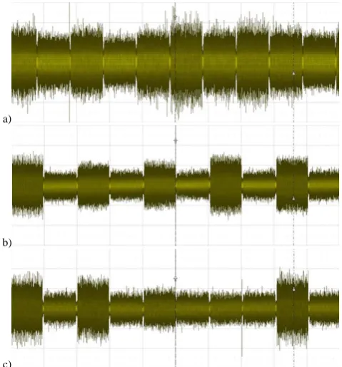
The power supplies have to be analyzed in terms of the resulting noise emission of switching regulators close to or in the favored communication spectrum. Various types of power supplies (2.5A, 4A, 8A) showed very highly differentiated negative impacts. Noise analysis with conventional industry certified power supplies demonstrated a very significant increase of the noise level in the frequency range 1 to 10 MHz with an increasing power class. We could measure, that the 8A power supplies have been under a higher noise level with minimum load than smaller power supply under full load. A measured noise
level of up to 1.8VPP using an 8A power supply with full load, 1.2VPP (load of 4A) and 0.8VPP (load of 0.2A) by using a 0.5VPP communication level seems to be extremely difficult to handle with. So it could be better to use two or three smaller power supplies to get a better noise level. See the following figures for detailed test readings.
[image:3.595.311.551.129.226.2]In case of the necessary of a strong power demand, maybe for supplying a large number of participants on the bus line, the implementation of a cascading multiple power supply to secure the electricity demand have to be specified after analyzing the exact behavior in the communication frequency range. These power supplies can be distributed over the entire cable length. However, the adaptation of the used data decoupling in this case, is always specifically to do. Depending on the uses communication version and Fig. 6. test platform with mainboard, digital processing unit (DPU),
transmitter board (TX), receiver board (RX) - topview
[image:3.595.72.263.162.346.2][image:3.595.308.554.266.367.2]
Fig. 7a. 4A power supply with 4A electrical load taken (time domain power supply noise)
Fig. 7b. 4A power supply with 4A electrical load taken (frequency spectrum of a communication)
Fig. 7c. 8A power supply with 0.2A electrical load taken (time domain power supply noise)
Fig. 7d. 8A power supply with 0.2A electrical load taken (frequency spectrum of a communication)
a)
b)
[image:3.595.312.554.410.508.2] [image:3.595.49.284.478.618.2] [image:3.595.307.554.546.641.2]system topology, an ampacity of up to 16A should be possible.
This goes along with the questions of how many carrier frequencies are used, what frequency distance is preferred and how many carriers should be modulated at the same time (group formation).
V. POSITION DEPENDENCE OF THE CLIENTS
The transmission levels (transceiver and receiver side) of the participants strongly depend to their position on the lines (see Figure 10). This requires a complex transmission power and receiver gain control. Particularly critical is the coupling of the data signal on the supply line. In our test cases, the data signal is generated by two identical current drivers (Fig. 8). The transmission power level can be varied over a gain control which is mandatory due to line reflections (localized amplification and attenuation).
In the receiver circuit, the differential data signal is coupled out and disturbing frequency components are filtered out. Afterwards the received signals are amplified. In order to avoid overloading a limiter is verifying the maximum amplitude of the amplified signal (Fig. 9). Because of using higher frequencies the signal attenuation is growing with increasing wire length. So the difficulty to distinguish between the signal and the noise becomes more complex. In this situation a termination resistor maybe could be the right way.
The origin of noise through the used coupling circuits, the active filters and amplifier stages will be reduced by optimizing these circuits, but cannot be avoided completely. The transmission levels of the participants while up-/download sequence (only one participant is sender or more participants are transmitting at exactly the same time) require topology dependent adaptation by different load conditions of the system to achieve all the same signal conditions.
Both, sender and receiver have to be as high impedance as possible to produce the lowest possible impedance load on the medium. This also applies for the designed data link to power the transmission and reception circuits out of the bus line (see Fig. 2).
The transformer winding inductance of the preferred data decoupling becomes more capacitive at higher frequencies. With increasing capacity the amount of the line impedance also increases. This means you need either more transmit power or you should shorten the cable length. A larger cable cross section would also drive the line capacity up[8].
We found out, if the described transmission technology is used in industrial data communication, also common mode interferences should be avoided. This could possibly be achieved by using a transformer coupling instead of the used coils. So coupling the data with absolutely symmetrical transmitter and receiver circuits to the differential lines can be passed. To symmetric adjust a test circuit made up of discrete components proves to be a very costly venture. A later ASIC realization of the symmetrical design would probably already much easier. For first analysis with prototypes it is an enormous complexity and should better be avoided.
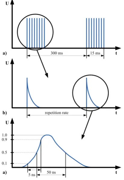
VI. BURST DISTURBANCE
[image:4.595.306.546.126.384.2] [image:4.595.53.277.262.394.2]Burst pulses are typically conducted transients on supply lines, ground or earth conductors with short rise times, low energy content and a wide frequency range at high repetition rate [9]. Special pulse generators can vary the intensity and nature of the necessary pulses to get an impression about these effects appearing in the bus line. For suppression, the simplest case, SMD capacitors could be used. These show typical low-pass behavior. It should be noted after extensive testing that at the time of the burst pulse (both positive and negative pulses made of 0.3 up to 1.1kV as a burst test in accordance with IEC61000-4-4) nearly all OFDM modulated information on the bus through Fig. 8. Used transmitter design
Fig. 9. Used receiver design
a)
b)
c)
Fig. 10. Different transmission levels depending on the line location a) 50m line, transmitter at the beginning, 20 receivers separated on the
line, point of measurement after 50m
b) 150m line, transmitter at the beginning, 20 receivers separated on the line, point of measurement after 100m
[image:4.595.47.296.517.595.2]the broadband glitch were destroyed, and no communication comes into existence. New strategies are needed, to reach the industrial criterion. Mode interference by the burst pulse should be rated as critical system parameters.
Regarding to the test system, also a ground bounce on the FPGA pins will result in broken input and output signals (under- and overshoot). In special circumstances this favors the effective lost of resolution for the used upstream and downstream transducers. At very high ground bounce effects, the parasitic diodes of the FPGA pins are conducting, which can also lead to malfunctioning of the entire design.
VII. CROSSTALK TO ADJACENT LINES
One typical scenario in industrial data transmission is the installation of cables in direct distance to each other. This may for example result from the installation in cable channels or in electrical cabinets. In this case, crosstalk from one to the other line is undesirable and in any case to avoid. The crosstalk effects (crosstalk on physically adjacent lines) have to be considered critically in the process automation. Because of the missing shield of our physical medium, this point may be neglected under any circumstances (studies such as near end crosstalk (NEXT) and far end crosstalk (FEXT) are mentioned here only by name) [10].
For this reason, special attention to these issues was adapted in the measurements. Tests have shown that it can be exposed to a cross-talk with the used system parameters. The crosstalk problem only appears when a data request transmission from the first circuit is temporally exactly simultaneous with a response transmission of the 2nd circuit (Fig. 12.b). A signal drift between the two circuits is generated through different oscillator accuracies. The moment of a critical crosstalk maybe appears in a periodic stable interval.
Measurements show that placing an OFDM modulated system in an industrial environment, a lot of emphasis on the assessment of available and needed carrier frequencies have to be done. New strategies have to be evaluated to support the carrier redundancy, the really necessary FFT sampling points and the clock accuracy of the used transmitter and receiver circuits.
Maybe there is a need to widen the frequency band with an increasing number of participants to higher frequencies, so that more carriers per participant are available or of course the number of participants themselves may rise up. If you try to include more participants in the already used frequency band, so the carrier spacing would be reduced and the accuracy of the algorithms must be adapted because of a decreasing fail-safe.
Although by increasing the number of channels (number of used carrier frequencies), the efficiency can be increased in principle, but this is definitely an increase in computational complexity and system delay and is directly bundled with the already existing multicarrier methods unfavorable high "peak-to-average" performance ratio [11].
Also an increase of the conversion resolution, or an over-sampling might be worth considering. This results of course in massive cost explosion for later ASIC designs. The necessary of a complex carrier allocation strategy is growing up with the length of the line, the number of used carrier frequencies, their spacing and the used frequency band. These problems are specially caused by the use of an unshielded line.
The carrier quality quantification at the time of system start-up and permanent quality assessment during operation in terms of noise coupling seems to be a basic requirement for the ability to introduce such a system.
VIII. CONCLUSION AND FUTURE WORK
In principle, it is possible to adapt a modified OFDM method for industrial data communication. The resulting enormous computational effort, the through prototypical building sensitivity and error-prone, especially in the analog transmitter and receiver stage, are seen as the biggest a)
[image:5.595.65.271.101.399.2]b)
Fig. 12. crosstalk effects depending on the line coupling
a) only crosstalk effects when request circle 1 and response circle 2 in exactly same time window
[image:5.595.299.550.149.343.2]b) no crosstalk effects
obstacle to introduce such a system within the next time in industry. To get this a really stable and comfortable to handle system, some years will be needed.
In addition, entirely new problems arise and open questions regarding to what kind of diagnosis and failure analysis such a system should be used. They should be able to handle different carrier allocation procedures. Depending on the participant location and line parameters different data transmission levels have to be interpreted.
Industrial users will only get involved to such a new system, if the appropriate development and diagnostic tools are provided.
The development of complex carrier allocation algorithms, data protection and new diagnostic strategies become a more necessary and substantial research field within the next years. But it will be worth it.
REFERENCES
[1] G. Schnell, “Bussysteme in der Automatisierungstechnik – Grundlagen und Systeme der industriellen Kommunikation” Braunschweig/Wiesbaden: Vieweg Verlag, 2000.
[2] VDI Standard 3687, “Selection of field bus systems by evaluating their performance characteristics for industrial applications” Berlin: Beuth-Verlag, 1999.
[3] J. A. C. Bingham, “Multicarrier modulation for data transmission: an idea whose time has come.” IEEE Communications Magazine, Vol. 28, Nr.5, pp. 5 -14, May 1990.
[4] I. Kalet, “The multitone channel” IEEE Communications Magazine, Vol. 37, Nr.2, pp. 119-124, February 1989.
[5] J. W. Cook, R. H. Kirkby, M. G. Booth, K. T. Foster, D. E. A. Clarke, G. Young, “The noise and crosstalk environment for ADSL and VDSL systems” IEEE Communications Magazine, Vol. 37, Nr.5, pp. 73-78, May 1999.
[6] M. H. Hayes, “Statistical Digital Signal Processing and Modeling” John Wiley & Sons, 1996.
[7] R. Schur, “Impulse compression for OFDM transmission over time-varying multipath channels” IEEE Vehicular Technology Conference (VTC), September 2002.
[8] D. M. Welton, “Transmission Lines: Theory, Types and Applications” (Electrical Engineering Developments) [Hardcover], Nova Science Pub Inc, pp. 221-236, November 2011.
[9] IEC 61000-4-4 “Electromagnetic compatibility (EMC) - Part 4: Electrical fast transient/burst immunity test“, 1995-01
[10] J. K. Kerpez, “Near-end crosstalk is almost Gaussian” IEEE Transactions on Communications, Vol. 41, Nr. 1, pp. 670-672, January 1993.