Dynamic Analysis of a Double-sided Actuated
MEMS Oscillator Using Second-order Averaging
A. Bhushan,
Member, IAENG
, M. M. Inamdar, and D. N. Pawaskar,
Member, IAENG
Abstract—MEMS oscillators have numerous applications as ultra-sensitive sensors, switches, and signal-processing elements. An important class of MEMS oscillators is double-sided electro-statically actuated microbeams. This investigation is concerned with analytical study of nonlinear resonance behaviour of such oscillators using averaging method. We have modelled a microbeam oscillator using Euler-Bernoulli beam theory and Galerkin formulation. The model takes into account the classical nonlinearities of geometric and electrostatic origin along with the effects of both linear and nonlinear damp-ing. The formulated mathematical model is a single-degree of freedom quintic oscillator and contains both symmetric cubic and quintic nonlinearities and asymmetric quadratic and quartic nonlinearities. Second-order averaging method, in contrast to first-order averaging method which is suitable only for symmetric nonlinearities, has been employed to take into account both symmetric and asymmetric nonlinear terms. The averaging solution is validated by comparing the results with numerical solutions. Using our analytical solution, change in qualitative nature (hardening, mixed hardening-softening, and softening) of resonance curves with variation of DC voltage has been explained. Our analytical solution is a useful tool for practicing engineers for fast analysis of resonance curves of MEMS oscillators.
Index Terms—MEMS, resonance curves, averaging method, double-sided oscillator, electrostatic actuation
I. INTRODUCTION
M
INIATURISED devices of microelectromechanical systems (MEMS) are used as sensors [1], switches [2], [3], and signal processing devices [4]. These devices are actuated and their responses are detected using differ-ent electrostatic, magnetomotive, piezoelectric etc. methods. Electrostatic method is a principal way to operate MEMS os-cillators in which a beam is placed above a plate electrode or placed in between two parallel plate electrodes in capacitive arrangement [5], [6]. Biased DC and AC voltages between microbeam and plate electrode(s) are applied for driving the oscillator. This paper is concerned with nonlinear dynamics study of a double-sided electrostatically actuated microbeam oscillator.Dynamic responses of MEMS oscillators are nonlinear in nature primarily due to geometric nonlinearity of microbeam and electrostatic actuation nonlinearity. Younis and Alsaleem [1] have explored the importance of dynamic instability and
Manuscript received March 15, 2013. This work was supported by Department of Science and Technology, Government of India (Grant No. -SR/FTP/ETA-031/2009).
A. Bhushan is with the Mechanical Engineering Department of Indian Institute of Technology Bombay, Mumbai, India (email: [email protected]).
M. M. Inamdar is with the Civil Engineering Department of Indian Insti-tute of Technology Bombay, Mumbai, India (email: [email protected]). D. N. Pawaskar is with the Mechanical Engineering Department of Indian Institute of Technology Bombay, Mumbai, India (email: [email protected], phone: +91-22-2576-7548).
bifurcation of electrostatically actuated microbeam oscilla-tors in mass-sensing and switching applications. Stambaugh and Chan [2] have devised noise-induced switching in non-linear electrostatically operated torsional micromechanical oscillators. In a recent work, internal resonance between flex-ure and torsional modes of vibration has been used to achieve frequency stabilization in micromechanical oscillators [7].
Double-sided actuated microbeam oscillators have been investigated both theoretically and experimentally in earlier research works [6], [8]. Kacem et al. [6] have studied primary resonance behaviour of a double-sided actuated mi-crobeam resonator using first-order averaging method. They have observed hardening, softening, and mixed hardening-softening behaviour in primary resonance and the nature of resonance curves depends on the separation between electrodes plates and microbeam and magnitude of applied DC and AC voltages. Kacem and Hentz [9] have also experimentally demonstrated that mixed hardening-softening resonance behaviour can be achieved in electrostatically actuated micromechanical resonators. Double-sided actuated microbeam oscillators have also been experimentally studied by Shao et al. [10]. They have demonstrated that mechanical and electrostatic nonlinearities of third order can be canceled out at critical magnitude of electrostatic actuation and it results in improvement in critical vibration amplitude for linear operation of the oscillators. Mestrom et al. [8] have carried out numerical simulation of their experimental results of a double-sided actuated microbeam resonator. They ob-served softening behaviour in the resonance curves and they did numerical simulation using a single-degree of freedom model. Further Mestrom et al. [11] have also observed experimentally both hardening and softening behaviour in resonance curves. Juillard et al. [12] have proposed a closed-loop control scheme to achieve large amplitude motion for resonant accelerometer using double-sided actuation and detection techniques.
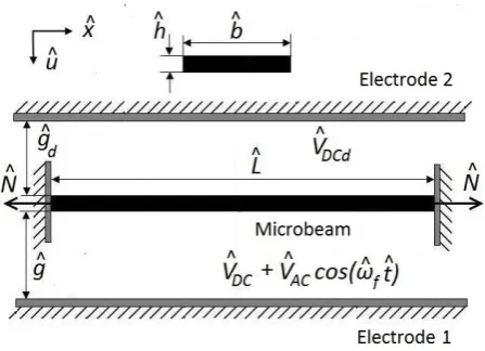
Fig. 1. Double-side actuation mechanism for a microbeam oscillator
nonlinearities, has been provided from averaging analysis to obtain resonance curves.The effects of asymmetric quadratic and quartic nonlinearities on resonance curves are quantified and an explanation of change in hardening to softening nature of resonance curves is provided.
II. DYNAMIC MODELLING
Figure 1 depicts double-side electrostatic actuation mech-anism for a microbeam oscillator of lengthLˆ, widthˆb, and thickness ˆh. The two electrodes 1 and 2 are placed at a separation ofˆgandˆgd from microbeam respectively. Biased
DC voltageVˆDC along with AC voltage of magnitude VˆAC
and driving frequency ωˆf are applied through electrode 1,
whereas only DC voltageVDCdis applied through electrode
2 in the electrostatic actuation. In double-side electrostatic actuation, electrode 1 is used for driving the oscillator and electrode 2 is used for detection of dynamic responses [6], [8]. In the symbol of variables, hat (ˆ.) is used to signify dimensional form of variable to differentiate it with their non-dimensional form which are introduced later.
Euler-Bernoulli beam theory has been used for modelling of microbeam motion by considering the fact that MEMS beams usually have high aspect ratios. The equation of motion of the microbeam oscillator is [13], [6]
ˆ
EIˆ∂
4uˆ
∂xˆ4 + ˆρAˆ
∂2uˆ
∂ˆt2 =
ˆ
EAˆ
2 ˆL
L
Z
0
∂uˆ
∂xˆ 2
dxˆ+ ˆN
∂2uˆ
∂xˆ2 + ˆF(ˆu)−Fˆd(ˆu),
(1)
where the boundary conditions are
ˆ
u|xˆ= 0= ˆu|xˆ= ˆL= ∂uˆ
∂xˆ ˆx= 0
= ∂uˆ
∂xˆ xˆ= ˆL
= 0·
In Eq. 1, uˆ(ˆx,ˆt) represents displacement of the microbeam whose properties are density ρˆ, effective Young’s modulus
ˆ
E, cross-sectional areaAˆ, and area moment of inertiaIˆ. The effect of axial residual stress in microbeam is accounted by applying uniform axial load Nˆ. Since the microbeam under consideration has fixed-fixed boundary condition, mid-plane beam stretching occurs during oscillation. It is a source of ge-ometric nonlinearity and accounted by introducing nonlinear axial force ∆ = ( ˆEA/ˆ 2 ˆL)R0Luˆ02dxˆ in Eq. 1. Fˆ(ˆu) and
ˆ
Fd(ˆu) are nonlinear electrostatic actuation forces provided
through the electrodes 1 and 2 respectively. The expressions forFˆ(ˆu) andFˆd(ˆu)are
ˆ
F(ˆu) =
ε0εrˆb
ˆ
VDC+ ˆVACcos(ˆωfˆt)
2
2 (ˆg−uˆ)2
ˆ
ζ(ˆu,ˆb,ˆh,ˆg),
ˆ
Fd(ˆu) =
ε0εrˆbVˆDCd2
2 (ˆg+ ˆu)2 ˆ
ζd(ˆu,ˆb,ˆh,gˆd)·
Here ε0 is vacuum permittivity, whereas εr is relative
per-mittivity which is taken 1 in this study. The expressions for ˆ
F(ˆu) and Fˆd(ˆu) are derived by calculating force between
infinite parallel plate electrodes separated by distance (ˆg−uˆ) and (ˆg+ ˆu) respectively. The effect of finite dimension of the microbeam can be accounted by including additional fringing field factors ζˆ(ˆu,ˆb,ˆh,ˆgd) and ζˆd(ˆu,ˆb,ˆh,gˆd) in
calculatingFˆ(ˆu) and Fˆd(ˆu)respectively. Many expressions
for accounting fringing field effects have been proposed and can be used according to the dimension of the microbeam [14], [15].
The non-dimensionalisation of Eq. 1 has been car-ried out for simplified representation using following non-dimensional variables
u= uˆ ˆ
g, x=
ˆ
x
ˆ
L, andt=
ˆ
t
ˆ
T·
Here Tˆ is a time constant, Tˆ = q
ˆ
ρAˆLˆ4/EˆIˆ. The
non-dimensional form of Eq. 1 is
u0000+ ¨u=
α1 1
R
0
u02dx+N
u00
+α2V2Fe(Ga, u)−α2VDCd2 Fe(Gd,−u)·
(2)
where the boundary conditions are
u|x= 0=u|x= 1=u 0
|x= 0=u 0
|x= 1 = 0·
Various coefficients of Eq. 2 are defined as
V =VDC+VACcos(ωft),
α1=
ˆ
Agˆ2 2 ˆI , N =
ˆ
NLˆ2
ˆ
EIˆ , α2= εrε0Lˆ4
g2EˆIˆ ,
ωf = ˆωfT , Gˆ a = 1, Gd=
ˆ
gd
ˆ
g , B0=
ˆ
b
ˆ
g·
In Eq. 2, VDC, VDCd, and VAC are represented in
dimensional form even without hat (ˆ.). We have neglected the effect of fringing field in this study i.e., the values of ˆ
ζ and ζˆd have been taken to be 1. So, the expression for
functionFe(Gi, λ)is
Fe(Gi, λ) =
B0
2 (Gi−λ) 2 ·
The governing integro-partial differential equation of mo-tion (2) of the microbeam oscillator has been reduced to a single-degree of freedom (SDOF) model using Galerkin based reduced order model technique [5]. The solution of Eq. 2 has been assumed in form
u(x, t) =φ1(x)u1(t), (3)
whereφ1(x) is pre-assumed first mode shape of a straight
beam under action of applied axial load N and u1(t) is
2 to an SDOF equation, the assumed solution (3) has been substituted in the equation, φ1(x)has been multiplied to it,
and finally it has been integrated from x= 0 tox= 1. The obtained SDOF equation is
¨
u1+ω12u1+k3u31=α2V2 1
R
0
Fe(Ga, φ1u1)φ1dx−
α2VDCd2 1
R
0
Fe(Gd,−φ1u1)φ1dx, k3=α1
R1
0 φ 02
1dx
2
·
(4) Hereω1is first natural frequency of the microbeam oscillator.
The magnitude of DC voltages VDC andVDCd, and/ or
separation between electrode plates and microbeam g and
gd can be different. In such asymmetric electrostatic loading
condition, the beam is deflected towards any one electrode plate depending upon the magnitude of DC voltages and electrode-microbeam separations. Equation 4 can be used to determine static deflection us0(x) =usφ1(x)by solving
the equation after neglecting the time dependent terms. The origin of Eq. 4 has been shifted to us by substituting
u1(t) =us+ud(t)in Eq. 4 and derive it in terms ofud(t).
The modified equation of motion becomes
¨
ud+c1u˙d+c3u2du˙d+ m
P
i=1
kiuuid=
V2 ACcos
2(ω
ft) + 2VDCVACcos(ωft)
C0+ m
P
i=1
Ciuid
(5) and
k1u=ω12+ 3k3u2s− VDC2 C1+VDCd2 C1d,
k2u= 3k3us − VDC2 C2+ VDCd2 C2d,
k3u=k3−VDC2 C3+VDCd2 C3d,
kqu=−VDC2 Cq +VDCd2 Cqd; q= 4, 5...m,
Ci= i1!α2 1
R
0
Fe(i)(Ga, usφ1)φi1+1dx; i= 0, 1, ...m,
Cid = (−1)i
i! α2 1
R
0
Fe(i)(Gd,−usφ1)φi1+1dx; i= 0,1, ...m·
Here the function Fe of Eq. 4 has been expressed in Taylor
series of order m. In Eq. 5, damping effects on oscillation is included by adding additional terms corresponding to conventional linear viscous damping c1u˙d and nonlinear
damping c3u2du˙d. Presence of nonlinear damping has been
observed in microbeam, nanotube, and graphene resonators in recent experiments [16], [17]. This motivates us to include a nonlinear damping term in the mathematical model of the microbeam oscillator.
By observing the coefficients of Eqs. 4 and 5, we can identify the contribution of geometric and electrostatic nonlinearities on different orders of nonlinear terms. Cubic nonlinearity is present in the straight microbeam oscillator due to beam stretching(k3u31)and is source of quadratic nonlinearity due
to deflected shape (contribution of 3k3us ink2u). However
VDC andVDCd contribute to all order of nonlinearities. An
important point needs to be mentioned here - in case of symmetric electrostatic loading (VDC=VDCdandg=gd),
asymmetric even order nonlinear terms vanish becauseusis
zero andCi andCid corresponding to even order nonlinear
terms are equal.
III. AVERAGING SOLUTION
A truncated form of Eq. 5 has been solved using pertur-bation method, second-order averaging [18]. The problem
under consideration for analytical treatment is
¨
ud+c1u˙d+c3u2du˙d+k1uud+k2uud2+k3uu3d+
k4uu4d+k5uu5d= 2VDCVACC0cos(ωft)·
(6)
We have been investigated near primary resonance where di-rect harmonic excitation2VDCVACC0cos(ωft)is the
dom-inant factor. The effects of other excitation terms consist parametric excitations and V2
ACcos2(ωft) terms are very
small, in compare to direct harmonic excitation, on primary resonance curves and this will verify by comparing the numerical solution of Eq. 5 and averaging solution of Eq. 6 in Section IV. In this investigation, we limit our study till fifth order nonlinear terms. We show in Section IV that at least till fifth order nonlinearity is necessary to be considered in dynamic modelling to predict the hardening, softening, and mixed hardening-softening behaviour of resonance curves of the investigated microbeam oscillator.
To solve the problem using averaging method, a pertur-bation problem has been formulated by introducing a small parameterin Eq. 6. The perturbation problem can be stated as
¨
ud+ωf2ud =εf (d)
1 (ud,u˙d, ωft) +ε2f (d)
2 (ud,u˙d, ωft),
f1(d)=−k21u2d−k41u4d, f (d)
2 =−µ1u˙d−µ3u2du˙d−
k31u3d−k51u5d+pcos(ωft)−∆1ud,
(7) and various coefficients are defined as
c1=ε20µ1, c3=ε20µ3, k1u=ω2n, k2u=ε0k21,
k4u=ε0k41, k3u=ε20k31, k5u=ε20k51,
2VDCVACC0=ε20p, ωn2=ωf2+ε20∆1·
Here 0 is another small parameter whose significance is
that when = 0, the solution of Eq. 7 is the solution
of Eq. 6. One thing important is to note here that the coefficients of quadratic and quartic nonlinearities k2u and
k4uare taken of order0, while other terms are taken of order
2
0. It can be shown that first order averaging is capable of
providing first approximation of symmetric nonlinear terms effects on resonance curves, whereas first order averaging of asymmetric nonlinear terms provides only the offset distance of oscillation from mean position as a first approximation. Therefore, we require second-order averaging solution to account for second approximation of asymmetric nonlinearity effects on resonance curves. In other words, such choice of a perturbation problem gives us first two approximations of asymmetric nonlinearity and first approximation of symmet-ric nonlinearity effects on dynamic responses. Equation 7 has been transformed in periodic standard form for making it suitable for averaging analysis using following co-ordinate transformation
ud=x1cos(ωft) +x2sin(ωft),
˙
ud= (−x1sin(ωft) +x2cos(ωft))ωf·
The periodic standard form of Eq. 7 is
˙
x1=−
ε ωf
f1(d)+εf2(d)sin(ωft),
˙
x2=
ε ωf
f1(d)+εf2(d)cos(ωft)·
TABLE I
PROPERTIES OF THE INVESTIGATED MICROBEAM OSCILLATOR
Length Width Thickness Effective Density Axial
ˆ
L(µm) ˆb(µm) hˆ(µm) Young’s ρˆ(kg/m3) load Modulus Nˆ (µN)
ˆ
E(GPa)
210 100 1.5 166 2332 110
Finally, Eq. 8 has been solved using second-order averaging method [18] and the averaged equations are
˙
y1=−
c1 2 +
c3
8r
2y
1+ Ω +γ2r2+γ4r4+γ6r6
y2,
˙
y2=−
c1 2 +
c3
8r
2y
2− Ω +γ2r2+γ4r4+γ6r6
y1
+2VDCVACC0 2ωf
,
(9) where
r2=y21+y22, Ω = ω
2 n−ω
2 f
2ωf
, γ2= γ (s) 2 −γ
(as) 2 ,
γ4= γ (s) 4 −γ
(as) 4 , γ
(s) 2 =
3k3u
8ωf
, γ2(as)= 5k
2 2u
12ω3 f
, γ4(s)= 5k5u
16ωf
, γ(4as)=7k2uk4u 8ω3
f
, γ6=−
63k42u
160ω3 f
· (10)
The averaged equations (9) is an autonomous system and its fixed points provide the periodic solutions of Eq. 6. The averaged equations are presented in co-ordinates [y1y2]T.
And these are related to the co-ordinates of periodic standard form (8) by relations x1(t) = y1(t) +v1(t) and x2(t) =
y2(t) +v2(t), where [v1 v2]T has been calculated during
first averaging. Since contribution of[v1 v2]T is of order,
[y1y2]T predominantly decides the amplitude of vibration.
The steady state solution of Eq. 9 can be expressed in a form of a nonlinear algebraic equation by expressing [y1 y2]T in
polar co-ordinates asy1=rcos(θ)andy2=−rsin(θ), the
nonlinear algebraic equation is
r2
c1
2 +
c3
8r
22+ Ω +γ
2r2+γ4r4+γ6r6
2
=
2VDCVACC0
2ωf
2
·
(11) This algebraic equation is in implicit form of variables forcing frequency ωf and amplitude of vibration r and its
solution provides resonance curve in amplitude-frequency plane.
IV. RESULTS AND DISCUSSION
We have studied primary resonance behaviour of a mi-crobeam oscillator whose properties are given in Table I. This microbeam has been investigated by Younis and Nayfeh [13] as a single-sided driven oscillator using perturbation method, method of multiple scales. We have solved Eq. 5 using a nonlinear dynamics software XPPAUT which is capable of obtaing resonance curves by continuation of periodic solution. [19]. The numerical solutions of Eq. 5 and 11 are compared with Younis and Nayfeh result in Fig. 2. Here gap ˆ
g is 1 µm, VDC is 8 V, VAC is 0.03 V, and quality factor
[image:4.595.47.292.190.355.2]is 1000. Both XPPAUT and averaging solutions are in good agreement with Younis and Nayfeh result.
Fig. 2. Comparison of numerical solutions of a single-sided driven beam oscillator with the results of Younis and Nafeh [13] forVDC = 8 V and
VAC = 0.03 V
Fig. 3. Resonance curves of the microbeam oscillator forVDC=VDCd
= 3 V andVAC= 0.015 V
We have studied the hardening to softening transition of resonance curves with variation of magnitude of DC voltages using Eq. 11 which has been obtained from averaging method. It is a nonlinear algebraic equation and has been solved in computational software Mathematica [20] for de-termining resonance curves. The transition study has been carried out by studying resonance curves for three different cases of electrostatic actuation which are depicted in Figs. 3, 4, and 5. For all the three cases, the gaps ˆg and gˆd
have been taken 1.00µm and 0.75µm respectively, whereas nonlinear damping has been neglected and quality factor has been taken 5000. The magnitudes of VDC, VDCd, andVAC
corresponding to Figs. 3, 4, and 5 are presented in Table II. In the figures, solutions of Eq. 11 have also been compared with the numerical solutions of Eq. 5. Both solutions are matching well and it justifies the choice of including only direct harmonic excitation term 2VDCVACC0cosωft and
neglecting the other components of dynamic excitation of Eq. 5 for the analytical investigation.
The resonance curves display hardening behaviour in Fig. 3, here applied DC voltagesVDC andVDCd are 3 V. When
[image:4.595.314.540.271.438.2]Fig. 4. Resonance curves of the microbeam oscillator forVDC=VDCd
= 6.5 V andVAC = 0.01 V
Fig. 5. Resonance curves of the microbeam oscillator forVDC=VDCd
= 10 V andVAC = 0.005 V
magnitude of DC voltages changes the values of coefficients
γ2, γ4, and γ6 of Eq. 10, which eventually determine the
nature of resonance curves. Since γ2 is coefficient of r2 in
Eq. 11, its magnitude decides the nature of resonance curve at small amplitude. The resonance curves display hardening behavior in nonlinear regime for positive value of γ2 and
softening for negative value. In a similar way, γ4 affects
nature of resonance curves relatively at higher amplitude because it is the coefficient of r4. The values of γ
2 and
γ4 are also shown in Table II when ωf = ωn. The value
of γ2 is positive and γ4 is negative when the applied DC
voltages are 6.5 V, so resonance curves display hardening behaviour at smaller amplitude in Fig. 4 and softening at higher. Resonance curves display softening nature in Fig. 5 because magnitudes of both γ2 and γ4 are negative for
applied DC voltages 10 V. In case of VDC =VDCd= 3V,
γ2 is positive and γ4 is negative, but the value ofγ4 is not
sufficiently higher thanγ2to counter the hardening effect of
γ2r2, so the resonance curves display hardening behaviour
till the maximum amplitude in Fig. 3.
In Table II, values of two more parameters are shown for all the three cases of electrostatic actuation:|γ2(as)/γ2(s)| and |γ4(as)/γ4(s)|; γ(2as),γ2(s),γ4(as), and γ4(s) are defined in Eq. 10. The parameter|γ2(as)/γ2(s)|signifies the contribution of quadratic nonlinearity, relative to cubic nonlinearity, in
TABLE II
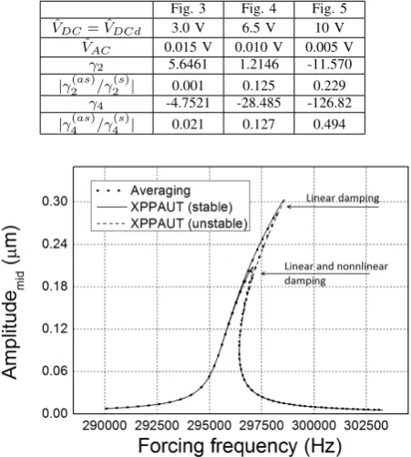
VALUES OF NONLINEAR PARAMETERS FOR THREE DIFFERENT CHOICES OF ELECTROSTATIC ACTUATION
Fig. 3 Fig. 4 Fig. 5
ˆ
VDC= ˆVDCd 3.0 V 6.5 V 10 V
ˆ
VAC 0.015 V 0.010 V 0.005 V
γ2 5.6461 1.2146 -11.570
|γ(2as)/γ2(s)| 0.001 0.125 0.229
γ4 -4.7521 -28.485 -126.82
|γ(4as)/γ4(s)| 0.021 0.127 0.494
Fig. 6. Effect of nonlinear damping on resonance curves forVDC = 5 V,
VDCd= 1 V, andVAC = 0.06 V
computation ofγ2. Whereas the parameter |γ (as) 4 /γ
(s) 4 |
sig-nifies the contribution of quadratic and quartic nonlinearities, relative to quintic nonlinearity, in computation of γ4. One
can observe from the table both|γ2(as)/γ(2s)|and|γ4(as)/γ(4s)| increase as magnitudes of DC voltages increase. If we neglect the effect of asymmetric nonlinearities, which are present here due to difference in magnitudes ofg andgd, in
determination of resonance curves, there can be significant error when applied DC voltages have large magnitude.
Until now, we have not included the effects of nonlinear damping on resonance curves. In Fig. 6, the effects of nonlin-ear damping on resonance curves are shown. Here, the linnonlin-ear damping coefficient c1 is corresponding to quality factor
1000 and nonlinear damping coefficientc3is 100 times ofc1.
Two resonance curves are plotted in the figure corresponding to electrostatic actuation VDC = 5 V, VDCd = 1 V, and
VAC = 0.06 V. The effects of both linear and nonlinear
damping are included in one resonance curve, whereas only effects of linear damping are considered in other resonance curve. We can observe from figure that the main effect of nonlinear damping is decrement of maximum amplitude of the resonance curve. This observation is consistent with the observation of Zaitsev et al. [17].
V. CONCLUSION
[image:5.595.56.284.265.424.2]to asymmetric electrostatic loading on resonance curves. The analytical model is a nonlinear algebraic equation and it can be used for fast computation of resonance curves during design phase of double-sided actuated microbeam oscillators.
REFERENCES
[1] M. I. Younis and F. Alsaleem, “Exploration of new concepts for mass detection in electrostatically-actuated structures based on nonlinear phenomena,” Journal of Computational and Nonlinear Dynamics, vol. 4, no. 021010, 2009.
[2] C. Stambaugh and H. B. Chan, “Noise-activated switching in a driven nonlinear micromechanical oscillator,”Physical Review B, vol. 73, no. 172302, 2006.
[3] M. M. Joglekar and D. N. Pawaskar, “Estimation of oscillation period/switching time for electrostatically actuated microbeam type switches,”International Journal of Mechanical Sciences, vol. 53, pp. 116–125, 2011.
[4] J. F. Rhoads, S. W. Shaw, K. L. Turner, and R. Baskaran, “Tunable mi-croelectromechanical filters that exploit parametric resonance,”Journal of Vibration and Acoustics - Transactions of the ASME, vol. 127, pp. 423–430, 2005.
[5] A. Bhushan, M. M. Inamdar, and D. N. Pawaskar, “Investigation of the internal stress effects on static and dynamic characteristics of an electrostatically actuated beam for MEMS and NEMS application,”
Microsystem Technologies, vol. 17, pp. 1779–1789, 2011.
[6] N. Kacem, S. Hentz, D. Pinto, B. Reig, and V. Nguyen, “Nonlinear dynamics of nanomechanical beam resonators: improving the perfor-mance of NEMS-based sensors,”Nanotechnology, vol. 20, no. 275501, 2009.
[7] D. Antonio, D. H. Zanette, and D. L´opez, “Frequency stabilization in nonlinear micromechanical oscillators,”Nature Communication, vol. 3, no. 806, 2012.
[8] R. M. C. Mestrom, R. H. B. Fey, J. T. M. Beek, K. L. Phan, and H. Nijmeijer, “Modelling the dynamics of a MEMS resonator: Simulations and experiments,”Sensors and Actuators A: Physical, vol. 142, pp. 306–315, 2008.
[9] N. Kacem and S. Hentz, “Bifurcation topology tuning of a mixed behavior in nonlinear micromechanical resonators,”Applied Physics Letters, vol. 95, no. 183104, 2009.
[10] L. C. Shao, M. Palaniapan, and W. W. Tan, “The nonlinearity cancellation phenomenon in micromechanical resonators,”Journal of Micromechanics and Microengineering, vol. 18, no. 065014, 2008. [11] R. M. C. Mestrom, R. H. B. Fey, K. L. Phan, and H. Nijmeijer,
“Simulations and experiments of hardening and softening resonances in a clamped-clamped beam MEMS resonator,”Sensors and Actuators A: Physical, vol. 162, pp. 225–234, 2010.
[12] J. Juillard, A. Bonnoit, E. Avignon, S. Hentz, and E. Colinet, “Large amplitude dynamics of micro/nanomechanical resonators actuated with electrostatic pulses,”Journal of Applied Physics, vol. 107, no. 014907, 2010.
[13] M. I. Younis and A. H. Nayfeh, “A study of the nonlinear response of a resonant microbeam to an electric actuation,”Nonlinear Dynamics, vol. 31, pp. 91–117, 2003.
[14] V. Leus and D. Elata, “Fringing field effect in electrostatic actuator,” TECHNION Israel Institute of Technology, Tech. Rep., 2004. [15] R. C. Batra, M. Porfiri, and D. Spinello, “Electromechanical model of
electrically actuated narrow microbeams,”Journal of Microelectrome-chanical Systems, vol. 15, pp. 1175–1189, 2006.
[16] A. Eichler, J. Moser, J. Chaste, M. Zdrojek, I. Wilson-Rae, and A. Bachtold, “Nonlinear damping in mechanical resonators made from carbon nanotubes and graphene,”Nature Nanotechnology, vol. 6, pp. 339–342, 2011.
[17] S. Zaitsev, O. Shtempluck, E. Buks, and O. Gottlieb, “Nonlinear damp-ing in a micromechanical oscillator,”Nonlinear Dynamics, vol. 67, pp. 859–883, 2012.
[18] J. A. Murdock,Perturbations: Theory and Methods. New York: John Wiley & Sons, Inc., 1991.
[19] B. Ermentrout,Simulating, analyzing, and animating dynamical sys-tems - A guide to XPPAUT for researchers and students. Philadelphia: Society for Industrial and Applied Mathematics, 2002.
![Fig. 2.Comparison of numerical solutions of a single-sided driven beamoscillator with the results of Younis and Nafeh [13] for VDC = 8 V andVAC = 0.03 V](https://thumb-us.123doks.com/thumbv2/123dok_us/1273325.655424/4.595.314.540.271.438/comparison-numerical-solutions-single-driven-beamoscillator-results-younis.webp)