Design Optimization of Mold for Dust Proof Cap
Swapnil J. Bhdane1, S. V. Ingle2
1
Research Scholar,Mechanical Engineering Department,,MET’s Institute of Engineering Bhujbal Knowledge City, Nashik,
2
Assistant Professor,Mechanical Engineering Department, MET’s Institute of Engineering Bhujbal Knowledge City, Nashik,
Abstract: Mould Design helps designers to improvement and quality of an injection molded part is dependent on many factors. These processes consider geometric parameters subjected to with the mold design and gate value system modification as well as process parameter such as molding condition during the filling phase. In the complete paper. The problem of optimization mold was addressed in this paper; the optimization problem can be broken into the subparts. The process is divided by using 3D printing product design for mold manufacturing effectively eliminates the use trial and error method by optimizing and validating the design of plastic products before production. This not only improves the quality but also helps to guide about the selection of machines and production planning An approximate feasible molding space (AFMS) is first determined to constrain the search space for the optimization. Quality is quantified as a function of simulation output and constitutes the objective function that must be minimized.
Keywords: Mould Design, Injection Molding, Optimization plastic injection mold, 3D printing, Approximate Feasible Molding space, Unigraphics(NX.06), mold wizard
I. INTRODUCTION
Protective dust caps and plugs play a crucial role in the life of quick coupling. Dust protection shields the connecting surfaces of couplers and nipples from environmental dust and dirt when the coupling is not connected. Dust caps are generally threaded and secured by screwing it onto the end of the steam. Dustproof cap generally for protecting over control panels, vacuum pipe, suction pipe, plastic wraps, packaging for computer hardware. Also, the dustproof cap plays the role for parts that require flexibility for which it serves very well. The material used for this molding process is waterproof, dustproof, corrosion proof for an inner and outer layer.
II. ABOUTACTIONTAKEN
A. About 3D modeling & Drafting of plastic product
By using 3D CAD like Unigraphics NX 6.0 software we can design all types of concept parameter required for the mold design and product design. We can develop a type of 3D model and required view in understanding orientation. We can understand all type interference and motion of simulation [1]
B. 3D Printing
3D Printing plays an important role is a development of prototypes in short time. With the help of the prototyped model, we can check the aesthetics, ergonomics and the assembly of the product as well. We can create plastic as well as metal prototypes. Also, we can look at a number of possibilities for designing a mold.
C. Mold Design using Mould Wizard for an Optimum Solution.
Using Mold Wizard module of Unigraphics NX 6(Siemens product) the process of Mold Design can be done with ease as well as in the least time. This mold wizard generally helps for a user to create a first object mold drawing for next stage software mold base. You can select the shrinkage allowance for mold. Which type of ejector pin required, sprue bush, locating ring, sliders, runners, gating, and cooling line? By using mold wizard multiple molds is created automatically as per your requirement.[1]
III.LITERATUREREVIEW
A. Plastic Injection Molding
Molding is a manufacturing technique for making parts from a plastic material such as LDPE, HDPE, and Bayer 2407 or as per selection. The molten plastic is injected at high pressure into a mold, which is the inverse of the desired shape. The mold is made by a mold maker from metal; usually, the material mold is oil hardened non-shrinking steel and high carbon high chromium die steel. Platen size in inches considers 2.95 X 2.95= 122.0 X 106.3 (Inch) and mold thickness is generally 1.18 inch.
B. Factor consideration
Have classified the factors that affect the quality of a molded part into four categories: part design, mold design, machine performance and processing conditions. They have all factor consideration about injection molding such as injection pressure, clamping capacity and shot capacity of injection mold also the required factor such as temperature, pressure and shrinkage allowance. During manufacturing of the product in injection molding quality characteristics may affect due to drifting and shifting of processing condition caused by machine wear, change in environment or operator failure problem.[3]
C. Injection Molding
[image:2.612.183.422.325.449.2]Injection molding is the most commonly used manufacturing process for the fabrication of plastic parts. The First assembly considers an injection unit, and mold assembly and clamping unit. Here raw material gets poured into the hopper and then go to the heated area where a heated section is present then at desired temperature plastic material are getting heated called as a molten plastic then goes through the molded part where mold cavity gets presented. Heated raw material get poured into the cavity and subjected part mold get their place and then cool molten plastic and get the desired shape as per requirement.[4]
Fig 1. Injection Molding Machine
D. Failure and material Selection of Plastic Mold
[image:2.612.149.468.534.711.2]IV.METHODOLOGY
Fig 3. Methodology
V. MATERIALUSESFORMOLDING
The Material used for creating the mold base is MS and for core/cavity is OHNS. There are many types of plastic materials that may be chosen in the plastic injection molding process. Most polymers may be select, considering all thermoplastics, some thermoset material, and some elastomers. The Plastic that is softer and more flexible than other material. LDPE have lower tensile strength. It is not reactive at room temperature, except by strong oxidizing agent. LDPE withstand a temperature of 80 to 90 degree. The choice of a material for making injection molded product is not solely based upon the desired characteristics of the final part. LDPE have translucent and opaque variation. It is quite flexible and tough than other material.[5]
VI.DUSTPROOFCAP
A. Protective Plastic Caps
The dust-proof caps generally play a role in protecting the types equipment, product and different types of control panels of system form dust and external injuries while creating in transportation. In our project dustproof caps used an application in control panels. There are many times a problem arises in the transportation of control panel form one place to another place for the desired assembly gets completed as per requirements. While transporting the panels there are many times external dust get place in control panel of system, there is some air bubble bag are get used for the protection against the dust but this solution not give the perfect result which we want from that they create a lot of confusion while identifications of control panel because of they are fully packed by air bubble bag so from us we give the solution of that desired problem. We introduce a new product for overcoming the problem that is a dustproof caps for control panels which made of plastic with great identification numbers and codes as per customer requirements and with color codes.
PART
DESIGN
3D PRINTING
MOLD WIZARD
MOLD DESIGN
B. Problem Incurred
Dust protective cap is generally creating a problem with a material. Generally, the problem arises with the identification of cap which fit on the desired panel, and then the material flexibility is not proper as per requirement, density not in range. We required material like which not reactive at room temperature. Except for a strong oxidizing agent. Made in translucent and opaque variations. It is quite flexible and tough. For the mold design, first design is only produces a four component which is not a perfect design for the productivity and cost factor and as per given time requirement. There is always change in mold structure base and create in changes assembly structure.
C. Solution
There is a change in material like an LDPE which is perfect as per your application requirement.
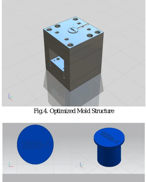
[image:4.612.185.425.273.573.2]Mold design which now gets a transfer into process of 3D printing and then goes to the mold wizard software which gets to help the proper design of the mold core and cavity. Now in a new design, we create a mold of eight product core which gives us an eight-component at a onetime which is better for us. For design now this time we only change in the cavity core and other structural things are same for all caps design
Fig.4. Optimized Mold Structure
Fig. 5. Actual component of cap
VII. CONCLUSIONS
VIII. ACKNOWLEDGMENT
The sources of every work of project required a lot of help, guidance and sources of many people and I am extremely thankful to have got this all information to completing of my project. Is not possible without under supervisions of project guide and sponsors helpful hand. “design optimization of mold for dust proof cap”
REFERENCES
[1] V. Shinde and B. Borkar, "design & analysis of plastic injection mould using nx-ug & delcam software", International Journal of Advance Reserch In Science And Engineering, vol. 5, no. 2, pp. 1-7, 2016.
[2] W. C, S. Shamsuddin, I. Napsiah and H. A.M.S., "Design and simulation of plastic injection molding process", International Journal of Plastic Product, vol. 5, no. 2, pp. 85-99, 2004.
[3] S. Kashyap and D. Datta, "Process parameter optimization of plastic injection molding: a review", International Journal of Plastics Technology, vol. 19, no. 1, pp. 1-18, 2015.
[4] A. Darekar, V. T, B. Patil and Y. Doctor, "Review of Optimization Aspects for Plastic Injection Molding Process", Engineering Science and Technology: An International Journal, vol. 5, no. 1, 2015.
[5] M. Salunke, R. Kate, V. Lomate and G. Sopal, "Review on Tool Design and Analysis ofInjection Moulding", International Journal of Mechanical Engineering and Technology, vol. 6, no. 6, pp. 33-42, 2018.
[6] Nagahanumaiah and B. Ravi, "Effects of injection molding parameters on shrinkage and weight of plastic part produced by DMLS mold", Rapid Prototyping Journal, vol. 15, no. 3, pp. 179-186, 2009.