265
©IJRASET: All Rights are Reserved
The Static Nonlinear Effect of Building Elements
with Collapse Mechanism during Earthquake
Kapil Mandloi1, Dr. Rajeev Arya2, Nitin Tiwari2, Rashmi Sakalle4
1
M. Tech Research Scholar,2Professor, 3Assistant Professor, Department of Civil Engineering, 4Associate Professor and Head, Department of Civil Engineering, Truba Institute of Engineering & Information Technology, Bhopal, M.P., India
Abstract: Formation of a single hinges in the building element generates a mechanics which causes the overall failure of the building. During the earthquake it is observe that the overall base reaction applied to the building at the base is much higher which caused the failure of base storey due to forming of such hinges in the building elements. The aim of this paper to identify such building elements which have to generate early hinges when the other building elements are much stronger.
Keywords: Earthquake, Hinges, Collapse Mechanism, identification of weakest building elements, Static Nonlinear Pushover Curve.
I. INTRODUCTION
Now a day we can see the such structures which have open ground storey with higher floor to floor height with respective of the other once which follows the nonlinearity in the structure. During the earthquake the overall building seismic force divides in the building floor diaphragms which generate greater at the ground storey caused the failure of the weakest building elements resulting collapse of the whole building. In the many aspects like architectural concepts like to open the ground storey with higher elevation make the building attractive in many views and the other one is that to uses of ground storey parking follows major nonlinearity in the structure. Walls filling structure are much stronger and having much strength compared to the above discussed structure. Such structure has greater ability to resist lateral forces upcoming during earthquake and the rigidity of monolithic structure is help to prevent the base story collapse. In the present scenario the existing buildings prepared by the earthen material (clay) bricks, fly ash bricks, hollow brick and many type of brick and stone masonry are used when they have to require. But the major disadvantages of such wall filling structure are that the non reliability due to the non understanding level of such structure forces and distribution of forces.
II. PROPOSEDBUILDINGMODELWITHDATA
All the data for building design are taken as per the Indian Standard Codes.
[image:1.612.43.221.485.693.2]A. Plan and 3D Model of the Proposed Building
Figure 1: Proposed Building Plan Figure 2: Grid System of Building Elements
[image:1.612.42.558.490.699.2] [image:1.612.237.381.500.690.2]266
©IJRASET: All Rights are Reserved
B. Allocation of Storey Number, Column and Beam Numbers
With help of alphabetic and numeric numbers of grid we can identify the building elements for example here G-(A1-B1) is G stand for Ground storey and A1-B1 is the horizontal building elements like beam. Same for column G1-A1 indicates column between ground floor to first floor.
TABLEI
STOREY NUMBERS
Sr. No. Building Parts No. Of Storey Storey Height
(m)
Cumulative Storey Height (m)
1 Foundation top to Ground
Floor
0 1 1
2 Ground Floor to First Floor 1 4 5
3 First Floor to Second Floor 2 3 8
4 Second Floor to Third Floor 3 3 11
5 Third Floor to Fourth Floor 4 3 14
6 Fourth Floor to Fifth Floor 5 3 17
7 Fifth Floor to Terrace 6 3 20
[image:2.612.57.531.152.484.2]C. Storey Drift
Table 2: Storey Drift
Sr. No. No. Of
Storey (m)
Storey Drift (mm)
Cumulative Storey Drift (mm)
1 0 0 0
2 1 16.54 16.54
3 2 26.99 43.53
4 3 36.52 80.05
5 4 44.85 124.90
6 5 51.30 176.20
7 6 55.23 231.43
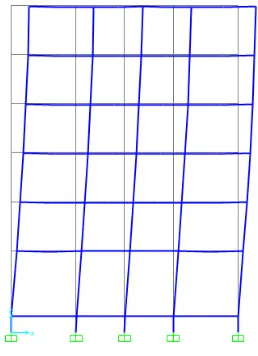
[image:2.612.109.238.504.682.2]D. Storey Drift in 2D and 3D Plan
[image:2.612.372.502.507.684.2]267
©IJRASET: All Rights are Reserved
III.PUSHOVERDEFORMEDSHAPEOFPROPOSEDBUILDING
A. Criteria for Acceptance
The scale which indicates the hinges in the various colours. They are used to indicate the state of the hinges when viewing the results of the analysis, but they do not affect the behaviour of the structure. Different type of colour indicates the different meaning of structure collapse. IO refers Immediate Occupancy, LS refers Life Safety, CP refers Collapse Prevention are the values of deformation that have been normalized by the same deformation scale factors used to specify the load deformation curve and typically located between point B and C and point B’ and C’ on the curve.
B. Step 1: Pushover Deformed Shape
[image:3.612.123.480.106.321.2]In this step (refer fig 8), some pink and blue hinges are generated. Hinges which have pink colour are in IO region and Hinges which have blue colour are in the LS region.
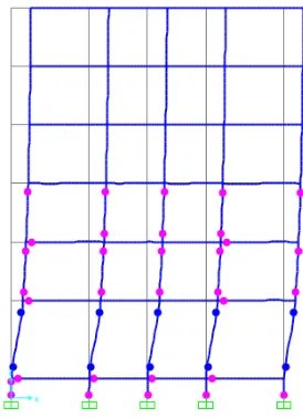
Figure 8: Step 1: Pushover Deformed Shape Figure 9: Step 2: Pushover Deformed Shape
C. Step 2: Pushover Deformed Shape
[image:3.612.364.500.460.646.2]In this step (refer fig 9), ground storey’s blue hinges are converted in the yellow hinges which crosses the CP region which causes the weaker such building elements which have such blue hinges. This are the first step to strengthening such building elements.
Figure 6: Graph Between Lateral Load vs Lateral
Deformation Figure 7: Pushover Deformation
[image:3.612.107.244.462.651.2]268
©IJRASET: All Rights are Reserved
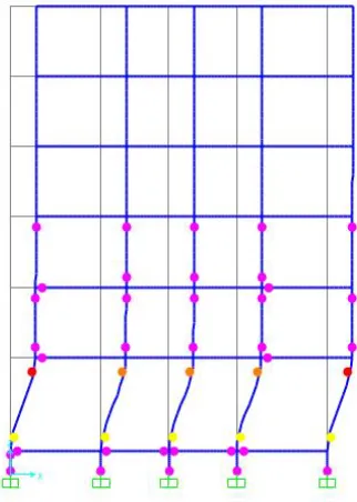
D. Step 3: Pushover Deformed Shape
[image:4.612.105.247.120.315.2]In this step (refer fig 10), two yellow hinges are converted to red hinges which means that this two building elements much weaker which causes the structure damage first.
Figure 10: Step 4: Pushover Deformed Shape Figure 11: Step 4: Pushover Deformed Shape
E. Step 4: Pushover Deformed Shape
In this step (refer fig 11), previous yellow hinges are converted to orange hinges which also means that this all building elements much weaker which causes the structure damage first.
F. Step 5: Pushover Deformed Shape
[image:4.612.368.503.125.313.2]In this step (refer fig 12), in the ground storey the red hinges are greater in the numbers that cause the collapse in the ground storey building elements which final cause the overall damage of the building.
[image:4.612.224.385.453.679.2]269
©IJRASET: All Rights are Reserved
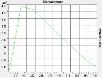
IV.STUDYONBASEREACTIONANDRESPECTIVEDISPLACEMENT
As we can see in the graph (refer fig 12), up to certain load the displacement are small after a peak value the displacement are so much with falling in the graph.
V. CONCLUSIONS
In the architectural consideration, which have higher ground storey in elevation causes a ground storey hinge mechanism, which have the overall failure of the building during earthquake. Wall filling floors makes the structure safe in many aspects. Due to ground storey mechanism excessive building drift occurs which have to damage the building.
In the open ground stored buildings the base reaction on the columns are higher. As we know that the modulus of elasticity of infill wall frame is directly proportional to the stiffness of the frame which is directly impact the seismic response of the frame.
Final result of this paper is that the higher elevation of the ground storey buildings has the large storey drift which have to excessive deformation at the ground level causes the ground storey mechanism. Due to this mechanism at the ground storey the overall structure collapse done.
REFERENCES
[1] H.S. Lee and S.W. woo, “Effect of masonry infills on seismic performance of A3 Storey RC frame with non-seismic detailing”, Earthquake Eng. Struct. Dyn.,
vol. 31, pp. 353-378, 2002
[2] M. Fardis, N. Bousias, G. Franchioni, and B. Panagiotakos, “Seismic response and design of RC structures with plan-eccentric masonry infills”, Earthquake Eng. Struct. Dyn., Vol. 28, pp. 173-191, 1999
[3] A. Saneinnejad, and B. Hobbs, “Inelastic design of infilled frames”. J. Struct. Eng., vol. 212, pp. 634-650, 1995.
[4] A. Rutenberg, G. Shoetand M. Eisenberger, “Inelastic seismic response of code design asymmetric structure”, Publ. Fac. Pub. 303, Faculty of Civil Engineering, Technion-Israel Institute of Technology, Haifa, 1989.
[5] M. Puglisi, M. Uzcategui and J. Florez-Lopez, “Modelling of masonry of infilled frames, Part I: the plastic concentrator”, Eng. Struct., vol. 31, pp. 113-118, 2009.
[6] M. Puglisi, M. Uzcategui and J. J. Florez-Lopez, “Modelling of masonry of infilled frames, Part II: cracking and damage”, Eng. Struct., vol. 31, pp. 119-124, 2009.
[7] D. Guney and E. Aydin, “The Nonlinear Effect of Infill Walls Stiffness to Prevent Soft Storey Collapse of RC Structures”,The Open Construction and Building Technology Jouurnal, 2012, 6, (suppl 1-M5) 74-80
[8] K. Meguro and H. S . Tagel-Din, “Applied element method used for large displacement structure analysis”, J. Nat. Disasters Sci., vol. 24, no. 1, pp. 25-34, 2002.
[image:5.612.200.395.118.267.2][9] H. A. Moghaddam, and P.J Dowling, “The State of the Art in Infilled Frames”, ECEE research Report no. 87-2. London: Civil Engineering Depatment, Imperial College of Science and Technology, 1987.