ISSN Online: 2327-5901 ISSN Print: 2327-588X
DOI: 10.4236/jpee.2019.710001 Oct. 18, 2019 1 Journal of Power and Energy Engineering
Numerical Analysis of the RAP Characteristics
of a Catamaran Vessel for Niger Delta Pliability
Daniel Tamunodukobipi, Samson Nitonye
Department of Marine Engineering, Rivers State University, Nkpolu, Port Harcourt, Nigeria
Abstract
A proper characterization of catamarans performance in relation to demi-hull separation ratio (Sc/L) is imperative for optimal design and applications. Re-sistance, propulsion and good sea-keeping characteristics for various de-mi-hull separation ratios at different operating conditions are prime consid-erations. This work evaluates the Resistance and Propulsion (RAP) characte-ristics of a 72 m long catamaran for various values of Sc/L (0.3, 0.4 and 0.5). Both physical models and numerical methods are implemented for the analy-sis. The analysis shows that the frictional resistance (RF) of catamaran is
pa-rabolic and slightly higher than those of monohulls. However, catamarans have superior sea-keeping performance. The RF of catamaran dominates the
total resistance (RT) at low speeds; however, at high Froude number (Fn >
0.25), wave-making resistance (Rw) becomes dominant, especially during humps. Consequently, the RT-curve and the effective power PE-curve oscillate
in rhythm with the Rw-curve as the velocity increases. Again, the effect of re-siduary resistance interference due to demi-hulls separation ratio is marginal, except during humps. Also, four speed-regimes are identified such as: 1) Low-speed (Fn < 0.23); 2) 1st hump (0.23 < Fn < 0.45); 3) Hollow-wave (0.45
< Fn < 0.60) and 4) 2nd hump, high-speed (Fn > 0.60). The catamaran P E for Fn > 0.6 is very high and uneconomical. Therefore, for optimal performance, catamarans should have service speed limits not exceeding Fn = 0.6.
Keywords
Resistance, Propulsion, Catamarans, Mono-Hull, High-Speed Craft
1. Introduction
A renewed interest in catamaran vehicles has emerged the development of un-conventional, high-speed, watercrafts, which are specially adapted for difficult
How to cite this paper: Tamunodukobipi, D. and Nitonye, S. (2019) Numerical Anal-ysis of the RAP Characteristics of a Cata-maran Vessel for Niger Delta Pliability. Journal of Power and Energy Engineering, 7, 1-20.
https://doi.org/10.4236/jpee.2019.710001
Received: July 24, 2019 Accepted: October 15, 2019 Published: October 18, 2019
Copyright © 2019 by author(s) and Scientific Research Publishing Inc. This work is licensed under the Creative Commons Attribution International License (CC BY 4.0).
http://creativecommons.org/licenses/by/4.0/
DOI: 10.4236/jpee.2019.710001 2 Journal of Power and Energy Engineering
terrain like the Niger Delta of Nigeria. A catamaran is a multi-hulled watercraft with two parallel demi-hulls of equal size. It has a broad beam with very reliable hydrostatic stability. Its remarkable sea-keeping characteristic is derived from its wide beams rather than the semi-submerged twin hulls. Catamarans range in sizes: from small sailing or rowing vessels to large naval ships. The vessel’s dis-placement volume is placed mainly below the waterline, where the influence of the waves is minimal. Thus, these vessels are very stable, even at high speeds and in rough sea conditions. Passenger catamarans satisfy requirements for speed, space and stability, as well as other functional needs of the users. Their swiftness and high sea-keeping performance make them a more preferred choice as passenger vessels than the conventional monohulls. However, in rough sea where high angles of heel occur, catamarans have shorter rolling periods than monohulls. The short rolling periods may cause great discomfort to passengers and crew [1].
This paper performs a detailed hydrodynamic design analysis of a high-speed catamaran adaptable to the Niger Delta terrains. The Resistance and Propulsion (RAP) characterization of the catamaran are performed using the theories of si-militude and classical fluid mechanics. The work analyzes the effect of variation in demi-hulls centers separation ratio (Sc/L) on wave resistance. Most investiga-tors [2][3][4] opined that the hull spacing was a key parameter in catamaran resistance determination, and increasing the hull spacing, invariably, would re-duce the interference effect, and hence lower the total resistance. However, no comparative study of this interference effect on resistance for different hull-spacings and speeds had been published. Therefore, this study entails performance evalu-ation of operating parameters and their dependencies on demi-hull separevalu-ation ratios, hull form and sea state. Different operating conditions are simulated to enable proper performance characterization and optimization of catamaran ves-sels. The design model developed in this work may improve design reliability, performance evaluation, parameter optimization and production cost minimiza-tion of catamaran [5].
2. The Catamaran Vessel
2.1. Development and Significance of Catamarans
The quest to improve sea keeping has led to development of the small-water- plane-area-twin-hull (SWATH) hull-forms. SWATH catamaran development was pioneered in Australia in 1972 by two sister firms: 1) Hercus Marine De-signs of New South Wales, and 2) Sullivan’s Cove Ferry Company. Since then different SWATH catamaran hull-forms and design features have evolved. In fact, there are over fifty different class-certified catamaran designs in existence
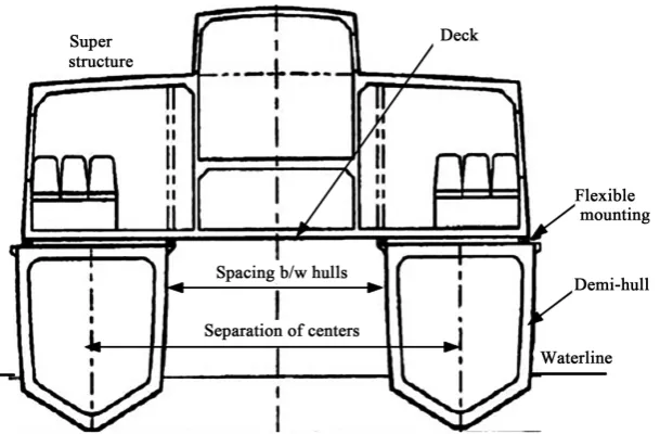
DOI: 10.4236/jpee.2019.710001 3 Journal of Power and Energy Engineering Figure 1. Schematics of a Catamaran showing twin demi-hulls.
Unlike basic catamarans, SWATH catamarans perform better than monohulls in minimizing wave resistance because the displacement parts of the twin hulls are submerged, while their interfaces with the water surface are slim and stream-lined. This allows the individual hulls to operate with very low possibility of wave-making resistance even at higher Froude number. In comparison with monohulls of equal displacements, catamarans have lower drafts [7]. However, these advantages are slightly offset by higher Frictional Resistance (RF) due to an
increased wetted surface area. Again, catamarans are very stable against roll mo-tion but susceptible to pitch and heave responses [8]. Nonetheless, contempo-rary SWATH catamarans are becoming increasingly popular in many areas of the marine transport industry and military operations. This is so, because of their excellent sea-keeping and stability characteristics to ensure riders’ comfort and safety. These unique attributes are major attraction for most industry profes-sionals who are keen about passenger-comfort while cruising at reasonably high speeds, even in rough sea, because they exhibit marginal falloff in speed with increasing sea state. The main disadvantages of catamarans are higher wetted surface for frictional drag and high stress concentration at points of at-tachment of the demi-hulls [9][10].
2.2. Design Features and Specification
DOI: 10.4236/jpee.2019.710001 4 Journal of Power and Energy Engineering Figure 2. Principal features, and general layout of machineries, and systems [12].
Two diesel fuel tanks placed inside the underwater hulls, one for each side, provide an endurance of more than 100 miles at full speed. As consequence of its high sensitivity to load changes, inside the demi-hulls: two mirrored ballast tanks have been fitted at the same position as the fuel tanks, to compensate for the loss of weight and trim change due to fuel consumption. On the other hand, when an AUV recovered is mounted, a weight increase occurs. This is balanced by de-ballasting the tanks as to make available some reserve buoyancy. That is achieved with two other seawater tanks of adequate capacity, normally full of ballast water, from which the fluid can be pumped out to release reserve buoyancy when an increase of weight occurs [13].
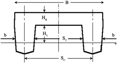
This system is important to maintain the design draft and trim of the vessel relatively constant under different loading conditions. Changes in its static atti-tude, due to draft reduction and trim variation, can induce an increase of the re-sistance. The latter is associated with free-surface waves generated, and geometry of the transverse cross-section of the demi-hulls. This may also affect the meta-centric height, and the center of pressure at the operating speed: and hence, the stability and survivability of the vessel at sea. Figure 3 shows the basic dimen-sions of the catamaran. If the metacentric height of the vessel is high enough, then the survivability of the vehicle is high while its response to waves excitation will be less [14][15].
where B and b are the overall beam of the craft and that of demi-hull, respec-tively; Sc and ST represent the separation between centers of the demi-hulls and
the transverse distance of the tunnel between the demi-hulls, respectively; while
HT and HB are the height of the underside of bridging structure above the design
water-line and the depth of the bridging structure, respectively.
2.3. Resistance and Propulsion (RAP)
The viscous Frictional Resistance (RF) of a catamaran is generally higher than
DOI: 10.4236/jpee.2019.710001 5 Journal of Power and Energy Engineering Figure 3. Principal catamaran dimensions.
catamarans is almost double that of monohulls. Whereas the wave resistance of a catamaran is usually smaller as compared to monohulls because of their streamline, slender demi-hulls. Sometimes, this advantage is compromised by the effect of wave interference, depending on the hull spacing (ST) at the
preva-lent Froude number.
Experimental techniques are until date considered the most reliable means of vessel parameters’ characterization. However, for economic reason, time wastage and susceptibility to error due to poor scaling and wall-effect, various robust theoretical models are being developed [16]. Havelock initial experiment utilized doublet which is made up of two small identical spheres submerged to the same depth but in fixed arbitrary distance apart [17]. The result of the doublet expe-riment showed that each sphere experienced, at various stream-velocities, higher wave resistance than when in solitude. It was also observed that the added resis-tance increased with decreasing separation of the spheres.
However, it reached a certain fixed maximum when the depth Froude number is about unity. Conversely, when other identical spheres were placed in different relative positions behind the former, the effects of wave interference were ob-served only where the trailing spheres occurred within the wave patterns of the leading spheres, for both the transverse and diverging waves. Havelock later ex-tended the investigation to include wave resistance and drift force of a ship un-der the influence of free-surface waves. It was found that the additional forces due to interference were of the same order magnitude as the wave resistance in still water [18].
The findings of Havelock led to the concept of twin hulls to improve seawor-thiness by Lewis [19] [20] and subsequently elaborated by Mandel [21]. Lewis and coworkers applied the same technology to study the motions of unconven-tional ships and semi-submerged vehicles in a seaway [22] [23]. It was estab-lished that during supercritical operation, the craft motion decreased as the speed was raised [24][25][26][27].
DOI: 10.4236/jpee.2019.710001 6 Journal of Power and Energy Engineering
rolling periods at larger angles of heel [28].
2.4. Speed and Propulsion
Service speeds of most passenger catamaran are greater than 50 knots (25.72 m/s). This is evidently enhanced by the lightweight aluminum-alloy construc-tion of the crafts, and the large power of propulsion. The most common propul-sion type is jet propulpropul-sion, where each water jet nozzle relates to one propulpropul-sion device. Water jet propulsion is more effective than screw propellers at speeds exceeding 30 knots (15.46 m/s), because of massive propeller-blades cavitation. Furthermore, combination of twin hulls with water jet nozzle results in excellent maneuverability at lower speeds, i.e. during berthing and un-berthing. There-fore, it is important that a proper spacing of the twin hulls be considered during de-sign to ensure good stability and effective maneuvering even in confined water [29].
2.5. Hybrid Catamarans Performance
So far, all SWATH catamaran ships above 500 tonnes have relative low speed of 15 knots (7.72 m/s) or less. However, speeds well over 20 knots (10.29 m/s) can easily be achieved with reasonable amount of power. Some developed and opti-mized for high sea-keeping performance, suffer from a higher RF because of larger submerged hulls. SWATH catamarans have significantly smaller length than equivalent conventional catamarans [30]. The reasons for that are to mi-nimize the:
Weight caused by the more deeply submerged twin hulls;
Wall-effect because smaller water plane area easily makes the necessary wider
hull spacing;
Frictional Resistance (RF)of the submerged hulls, since smaller lengths imply
a reduced wetted surface.
In general, SWATH configurations have relatively high resistance because their length and greater structural weight make them less slender than would be desirable. The solution, to this is a narrow form at the fore end of struts: such that at higher speeds the vessel is piercing waves, instead of shoving them [31][32].
2.6. Stability, Hull Form and Resistance
In case of conventional monohull vessels, stability is defined by the positions of center of gravity (G), the center of buoyancy and the resultant metacentric height. The allowable maximum center of buoyancy, above keel is ¼ of the ves-sel’s beam. However, catamaran’s configuration allows greater transverse shift of the center of buoyancy without inducing adverse upturning moments. It has high righting moments, even at reasonably large heeling angles [33]. Figure 4
shows the intact stability of a catamaran.
DOI: 10.4236/jpee.2019.710001 7 Journal of Power and Energy Engineering Figure 4. Intact stability of a catamaran [34].
important parameters. By increasing the hull spacing, it is possible to reduce in-terference effects, and hence the total resistance. Conversely, the acceleration of its righting moment due to heeling is higher: and thus, shortening the rolling period. Interference of wave systems is noticeable at the value of Froude number
Fn = 0.3 [35][36].
Therefore, it can be stated that the influence of hulls spacing on the resistance is quite enormous and complex. The total resistance depends on the operating speeds, hull-form parameters, hulls spacing, displacement and the prevalent sea state. For example, at high length-to-breadth (L/b) ratio of the demi-hulls, the effects of hull spacing have more influence on resistance than hull-form. Whe-reas, for very small L/b, the hull-form impacts significantly on the wave making resistance.
2.7. Sea Keeping and Resistance
For the same sea states, the rolling amplitudes of catamarans are about 2.5 times smaller than those of monohulls of equivalent displacements. The remarkable small angles of heel are elucidated by the large transverse stability. This implies that when a monohull experiences substantial rolling motion in waves, a cata-maran may remain unperturbed. However, this advantage becomes an issue at larger angles of heel. The upright moment is so strong (because of large righting moment arm, GZ) that it produces powerful and sudden return of the vessel to its stable upright position [37]. Such abrupt impact often causes momentary dis-sipation of propulsive force, and a great discomfort to passengers.
DOI: 10.4236/jpee.2019.710001 8 Journal of Power and Energy Engineering
one another. Under such sea state, the vessel resistance to forward motion is much higher.
3. Materials and Methods
Most works on catamarans are experimental, where hydrodynamic performance and RAP characteristics are determined. A vast amount of motion data has un-doubtedly been accumulated over the past two decades. However, Betts argued that the correct implementation of these data in design and performance analy-sis is cumbersome and capital intensive. Betts inanaly-sisted that data acquisition based on realistic operability criteria should be a top priority in research [38]. In practice, it is very difficult to simulate the exact sea state in a model testing facil-ity. The realistic operability criteria associated with vessel’s motion prediction are often compromised by simplifying assumptions. On the other hand, most predictive models, based on canonical resistance theory and data synthesis pro-grams used for conventional ships, are evidently unsuitable. Hence, for error-proof design of these hi-tech vessels, an appropriate combination of both theoretical analysis and experimental data is imperative. Consequently, this study employs both physical modelling and numerical method to determine the resistance and propulsion characteristics of catamaran.
[image:8.595.145.535.464.753.2]3.1. Catamaran Data Specification
[image:8.595.210.538.467.622.2]Table 1 and Table 2 present the specifications of the catamaran parameters and the sea water properties, respectively. These data are employed in the perfor-mance prediction of vessel.
Table 1. Specification of the SWATH catamaran [36].
Parameter Value
Velocity of hull (m/s) 3.41
Overall Length (m) 75.00
Overall Breath 53.00
Design Draught (m) 8.56
Hull Separation Ratio 0.2 - 0.5
Hull Length 72.00
Wetted Surface Area (m2) 32.3
Vessel displacement (tons) 1286
Table 2. Sea Water properties [23].
Parameter Value
Density, Kg/m3 1120
Kinematic Viscosity, m2/s 1.63 × 10⁻⁶
DOI: 10.4236/jpee.2019.710001 9 Journal of Power and Energy Engineering
3.2. Resistance of Catamaran
The resistance of a catamaran at a given speed U is the force required to tow it at that speed in calm water, without any interfering external forces. If the hull has no appendages, this is called “Bare-Hull Resistance”. The minimum power ne-cessary to overcome this resistance is called the effective power and is usually notated as EHP (Effective Horsepower): where 1.0 HP = 0.745 kW. The total re-sistance is the sum of a number of different components, which are caused by a variety of factors and which interact with each other in a rather complicated way. It is usual to consider the total calm water resistance as a function of fric-tional resistance, wave-making resistance, eddy or separation resistance, and viscous pressure drag.
3.3. Frictional Resistance
Frictional resistance is usually the most significant component of the total cata-maran resistance and is caused by the tangential fluid force resisting the forward motion of the vessel in a viscous fluid. For relatively slow ships with high block coefficient, it contributes to about 85% of the total resistance. Whereas, for high speed streamlined displacement hulls, it may drop to about 50%. These values may become higher in time due to the increased hull fouling or roughness [39]. The total RFof a SWATH catamaran can be written as:
(
)
20.5 1
F F w sh
R = +
δ ϕ ρ
k A U (1)where:
F
R → Total friction resistance of both hulls.
F
ϕ → Coefficient of.
w
ρ → Density of the water.
sh
A → Static wetted surface area of hulls.
U → Speed of the catamaran.
(
1+δ
k)
→ Form factor.The form factor is a function of slenderness ratio 3L∇
.
According to Couser et al.[40], the form factors are given as:
Catamaran →
(
)
0.4
3 1 δk 3.03 L
−
+ =
∇
(2)
Monohull →
(
)
0.4
3 1 k 2.76 L
−
+ =
∇
(3)
Consequently, the resultant frictional resistances are: Catamaran →
0.4
2 3
3.03 2
F L F w sh
R ϕ ρ A U
−
=
∇
(4)
Monohull →
0.4
2 3
2.76 2
F L F w
R ϕ ρ SU
−
=
∇
DOI: 10.4236/jpee.2019.710001 10 Journal of Power and Energy Engineering
where S is the wetted surface of a monohull and Ash represents the wetted
sur-face of the two demi-hulls of catamaran. The International Towing Tank Confe-rence (ITTC 1957) model-ship correlation line adopted the following equations
[40]:
(
)
20.0075 log 2
F
Re
ϕ =
− (6)
h UL
Re= ν (7) where:
Re → Reynolds number.
ν
→ Kinematic viscosity.h
L → Characteristic length of the hull.
3.4. Wave Making Resistance
The wave-making resistance (Rw) of a catamaran is the net fore-and-aft forces upon it due to the fluid pressures acting normally on all parts of the hull. If the body is traveling on or near the free surface, this pressure variation causes waves that radiate away from the body and carry with them a certain amount of energy that is dissipated in the ocean. The wave-making resistance can also be described as the energy expended by the catamaran to maintain the wave system. Theoret-ical determination of the wave-making resistance requires a knowledge of the wave system generated by a moving ship. Pham et al. [41] evolved a regres-sion-based procedure for the prediction of wave resistance coefficient of hard chine catamarans as:
( )
1 2 3
exp
W LB TB ScL
α α α
ϕ = ⋅ α
(8)
where: 10≤L B≤20,
1.5≤B T≤2.5, 0.4≤Cb≤0.6,
3
6.6≤ L ≤12.6
∇ .
However, Molland et al. [42] produced an abridged formula based on slen-derness ratio given by:
3 n
W a L
ϕ =
∇
(9)
and the catamaran, residuary resistance interference factor is expressed as:
3
W L
γ
ε = β
∇
. (10)
The corresponding wave-making resistance is
2
0.5
W W WS w sh
DOI: 10.4236/jpee.2019.710001 11 Journal of Power and Energy Engineering
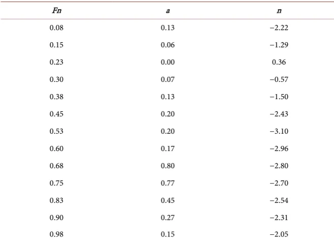
[image:11.595.209.538.216.454.2]where coefficients (a, β) and the exponentials (n, γ) are given in Table 3 and
Table 4.
The parameter εW is dependent on speed, slenderness (L 3∇), and
separa-tion ratio of the hulls (Sc L), but seemingly independent of the hull shape. The vessel speed sometimes is expressed in terms of Froude number
. U Fn
g L
=
. (12)
Table 3. Parameters for wave-making resistance.
Fn a n
0.08 0.13 −2.22
0.15 0.06 −1.29
0.23 0.00 0.36
0.30 0.07 −0.57
0.38 0.13 −1.50
0.45 0.20 −2.43
0.53 0.20 −3.10
0.60 0.17 −2.96
0.68 0.80 −2.80
0.75 0.77 −2.70
0.83 0.45 −2.54
0.90 0.27 −2.31
[image:11.595.199.539.487.738.2]0.98 0.15 −2.05
Table 4. Wave making resistance inference factor.
Fn Sc/L = 0.3 Sc/L = 0.4 Sc/L = 0.5
β γ β γ β γ
0.08 1.71 −1.1 0.12 0.72 1.25 −0.225
0.15 1.09 −0.89 0.26 0.62 1.11 −0.1
0.23 0.48 −0.68 0.4 0.52 0.97 0.025
0.30 0.14 0.47 0.54 0.42 0.83 0.15
0.38 0.75 0.26 0.68 0.32 0.69 0.275
0.45 1.36 0.04 0.82 0.22 0.55 0.4
0.53 1.55 −0.05 0.82 0.22 0.49 0.44
0.60 1.04 0.09 0.60 0.34 0.56 0.36
0.68 0.65 0.33 0.48 0.44 0.53 0.39
0.75 0.42 0.52 0.35 0.53 0.47 0.46
0.83 0.34 0.65 0.27 0.59 0.41 0.525
0.90 0.3 0.67 0.35 0.6 0.41 0.52
DOI: 10.4236/jpee.2019.710001 12 Journal of Power and Energy Engineering
3.5. Total Hull Resistance
The total hull resistance coefficient can be written as:
(
)
TS FS W WS k FM FS
ϕ
=ϕ
+ε ϕ
−δ ϕ
−ϕ
. (13)Thus, the total resistance of the catamaran becomes
2 1
2
T W sh T
R = ρ A ϕ U . (14)
The total (RT) is considered without air resistance. The latter is considered
when the effect of wind on the above-water part of the vessel is required.
3.6. Catamaran Propulsion
Traditionally, vessel’s speed versus power characteristic has been regarded as the most important factor in ship powering. Many advanced marine vehicles, such as surface effect ships, hydrofoil crafts and planning hull vessels were conceived and developed to overcome the speed limits of conventional displacement ves-sels [11]. All propulsion devices operate on the principle of imparting momen-tum to “working fluid” in accordance with Newton’s laws of motion:
The propulsive force acting on the vessel is equal to the rate of change of momentum of the working fluid.
Action and reaction are equal and opposite. So, the thrust is proportional to the rate of change of momentum but occurs in the reverse direction.
Thus, the force required to produce the momentum change in the working fluid appears as a reaction force on the propulsion device, which constitutes the thrust for propelling the vessel. Suppose the fluid passing through the device has its speed increased from V1 to V2, and the mass flow per unit time through the
device is m, then the thrust (T) produced is given by:
(
2 1)
T m V V= − . (15)
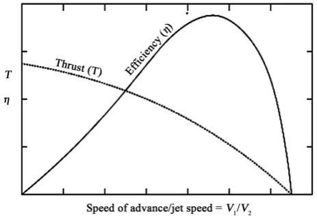
This indicates that as V1 → V2, T → 0. Thus, as the ratio of advance-speed (V1)
to jet speed (V2) increases towards unity, i.e. (V1/V2 → 1), the thrust decreases
[image:12.595.257.489.548.706.2]towards zero. This brings to Figure 5 that shows the two limiting situations:
DOI: 10.4236/jpee.2019.710001 13 Journal of Power and Energy Engineering
1) V1 = V2. Thrust is zero; hence, there is no useful power output (P = TV1).
At this condition, propulsive efficiency, ηp =0.
2) V1 = 0. At this point, although the device is producing maximum thrust
(bollard pull), no useful work is being performed (i.e. TV1 = 0) and, hence, again 0
p
η = .
Nevertheless, the effective power required to move the catamaran at the de-sign speed is given by
E T
P =R U. (16)
4. Results and Discussion
4.1. Frictional Resistance of a Catamaran
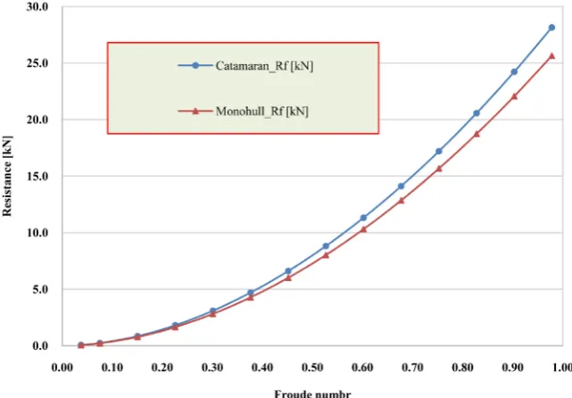
In Figure 6, the frictional resistance (RF) of the catamaran is plotter alongside
that of a monohull of equivalent displacement. The result indicates that the RF
experienced by a catamaran is parabolic like the monohull, but slightly larger in magnitude. This disparity is elucidated by an increase in wetted Surface due to the twin demi-hulls. Remember that RF is directly proportional to the wetted
Surface. This implies that at equal speeds and displacements, a catamaran will require more power than a monohull, provided other components of RT are
ig-nored.
4.2. Wave Making Resistance of a Catamaran
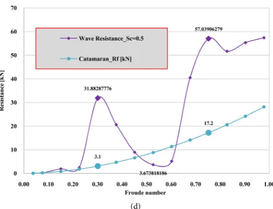
Figure 7 presents the wave-making resistance (Rw) of the catamaran plotted
[image:13.595.212.533.482.705.2]against motion Froude number (Fn) for various demi-hulls separation ratios (0.2 ≤ Sc/L ≥ 0.5). It is evident from the results that the wave resistance of the cata-maran fluctuates with increasing Fn. For instance, in Figure 7(a) with Sc/L = 0.2: Rw increases from 1.8 kN at Fn = 0.23 to 39.8 kN at Fn = 0.3, before falling
DOI: 10.4236/jpee.2019.710001 14 Journal of Power and Energy Engineering (a)
(b)
DOI: 10.4236/jpee.2019.710001 15 Journal of Power and Energy Engineering (d)
Figure 7. Dependence of wave-making resistance on froude number and separation ratio.
to 6.11 kN at Fn = 0.53, The same pattern is exhibited by catamarans with Sc/L
ranging from 0.3 to 0.5. This characteristic contour of Rw graphs can be ex-plained by the occurrence of Humps and Hollows in the waves systems. Humps result due to waves reinforcement, when the crests of two or more waves systems of the same frequency coincide to form larger crests. Hollows occur when there is cancellation of waves. The crests of one waves-system coincide with the troughs of another of equal frequency.
The formation of humps and hollows is dependent on the motion Froude number and the system of waves. During humps, Rw values are very high while the reverse is true with hollows: hence the alternating high and low values of Rw. Note that the analysis does not consider slamming drag and wall-effects. A clos-er obsclos-ervation of the wave-making and frictional resistances shows that for Fn > 0.6, the wave-making resistance is always higher than the frictional resistance.
4.3. Total Resistance of Catamaran
In Figure 8, the total resistance (RT) curve, for Fn < 0.25, is largely due to
visc-ous friction, and hence parabolic. However, with Fn > 0.25, the total resistance oscillates significantly because of the dominant influence of Rw as the velocity increases. Also, the results indicate that the effect of residuary resistance interfe-rence is substantial mainly during humps. However, at hollows, there is cancellation of waves: hence Rw and the residuary resistance interference are very low. Again, the RT peaks for Sc/L = 0.2 are higher than those of Sc/L ≥ 0.3.
This implies that a catamaran can operate with minimal resistance at Froude numbers where hollows occur irrespective of its Sc/L values. Thus, the design operating speed should essentially coincide with Fn at hollows for optimal pro-pulsive efficiency. Please note that the RF of any marine vessel is raised by larger
DOI: 10.4236/jpee.2019.710001 16 Journal of Power and Energy Engineering
4.4. Effective Power of Catamaran
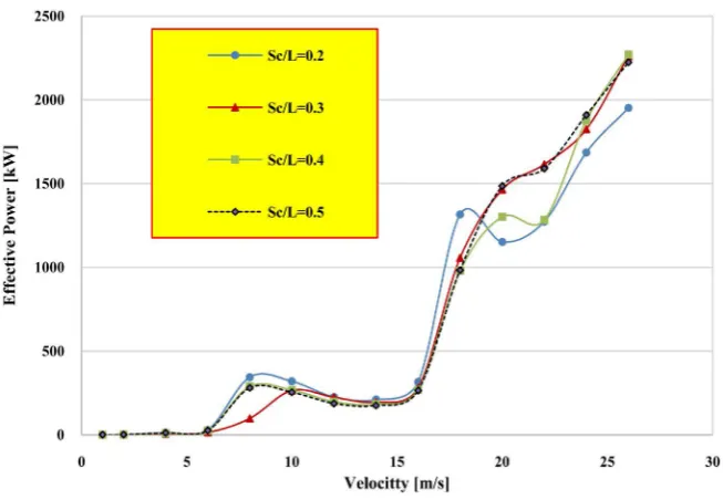
Some passenger catamarans have already exceeded 26 m/s (50.5 knots) service speed. Considering two vessels (1 and 2), their equivalent speed relation is
2 1 2 1
V V L L= . This implies that for equal Fn, larger catamarans have higher
equivalent speeds. In Figure 9, the investigated catamaran has four speed-reg- imes:
1) Low speed (Fn < 0.23) requires a minimum effective power (PE) of 26 kW
at. 6.25 m/s (12.2 knots);
2) 1st hump (0.23 < Fn < 0.45) requires a P
E = 277.8 kW at 8.0 m/s (15.6
[image:16.595.211.534.240.449.2]knots);
Figure 8. Total catamaran resistance variation with the ship velocity.
[image:16.595.210.537.482.708.2]DOI: 10.4236/jpee.2019.710001 17 Journal of Power and Energy Engineering
3) Hollow wave (0.45 < Fn < 0.60) needs a PE = 230.8 kW at 16 m/s (31.1
knots);
4) 2nd hump, high-speed (Fn > 0.60) needs P
E = 1775.6 kW at 26 m/s (50.5
knots).
The results indicate that it is counter effective and uneconomical to operate the craft above 16 m/s (Fn > 0.6) because of the astronomical increase in RT per
unit rise in speed. Therefore, for optimal performance, the craft should operate below 30 knots.
5. Conclusions
The performance characterization of a 72 m long catamaran is considered using hydrodynamic relations and numerical methods. The components of total resis-tance (RT) of the craft under different operating conditions and separation ratio
(Sc/L) are determined. Comparison between catamaran and monohull is carried out in terms of resistance and sea-keeping characteristics.
The analysis indicates that catamarans have slightly higher frictional resis-tance (RF) than monohulls. This is because a catamaran has larger wetted surface
than a monohull of equivalent displacement. However, this seeming disadvan-tage is considered inconsequential because of its attractive superior sea-keeping performance over monohulls. Furthermore, the RF experienced by catamaran
has a parabolic relationship with the vessel speed and dominates the total resis-tance at low speeds. However, at high Froude number (Fn > 0.25), wave-making resistance (Rw) dominates, especially during humps. Thus, the RT-curve and
hence the effective power PE-curve oscillate utterly in rhythm with the Rw-curve
as the velocity increases. Based on this, four speed-regimes are identified. They are: 1) Low-speed (Fn < 0.23); 2) 1st hump (0.23 < Fn < 0.45); 3) Hollow-wave
(0.45 < Fn < 0.60) and 4) 2nd hump, high-speed (Fn > 0.60) regimes. The
inves-tigation shows that PE for Fn > 0.6 is very high and uneconomical. The residuary
resistance interference due to demi-hulls separation ratio is inconsequential, ex-cept during humps.
Conflicts of Interest
The authors declare no conflicts of interest regarding the publication of this pa-per.
References
[1] Nitonye, S., Ogbonnaya, E.A. and Ejabefio, K. (2013) Stability Analysis for the De-sign of 5000-Tonnes Offshore Work Barge. International Journal of Engineering and Technology,3, 849-857. http://www.ijet.journal.org
[2] Stretensky, L.N. (1936)On the Wave-Making Resistance of a Ship Moving Along in a Canal. The London, Edinburgh, and Dublin Philosophical Magazine and Journal of Science, 22, 1005-1013. https://doi.org/10.1080/14786443608561754
DOI: 10.4236/jpee.2019.710001 18 Journal of Power and Energy Engineering
[4] Tasaki, R., Takahei, T. and Moss, J.L. (1963) Wave-Making Resistance Interference Effects on a Catamaran Model.
[5] Nitonye, S., Adumene, S. and Howells, U.U. (2017) Numerical Design and Perfor-mance Analysis of a Tugboat Propulsion System. Journal of Power and Energy En-gineering, 5, 80-98. https://doi.org/10.4236/jpee.2017.511007
http://www.scirp.org/journal/jpee
[6] Leopold, R. (1969) A New Hull-Form for High-Speed Volume-Limited Displace-ment Type Ships. SNAME Spring Meeting, Paper No. 8.
[7] Lewis, E.V. and Odenbrett, C. (1960) Preliminary Evaluation of a Semi-Submerged Ship for High-Speed Operation in Rough Seas. Journal of Ship Research, 4, 1-8. [8] Lin, W.C. and Day Jr., W.G. (1974) The Still-Water Resistance and Powering
Cha-racteristics of SWATH Ships. AIAA/SNAME Advanced Marine Vehicle Conference Paper, San Diego, CA, 25-28 February 1974.
[9] Havelock, T.H. (1936) Wave Resistance: The Mutual Action of Two Bodies. Pro-ceedings of the Royal Society of London, 155, 460-471.
https://doi.org/10.1098/rspa.1936.0112
[10] Pien, P.C. and Lee, C.M. (1972) Motion and Resistance of a Low-Waterplane-Area Catamaran. 9th ONR Symposium of Naval Hydrodynamics, Paris, 20-25 August 1972.
[11] Lankford Jr., B.W. (1967) The Structural Design of the ASR Catamaran Cross Structure. NavalEngineersJournal, 79,625-635.
https://doi.org/10.1111/j.1559-3584.1967.tb04017.x
[12] Daniel, T., Samson, N. and Adumene, S. (2018) Design Analysis of a Lightweight Solar Powered System for Recreational Marine Craft. World Journal of Engineering and Technology,6, 441-456. https://doi.org/10.4236/wjet.2018.62027
http://www.scirp.org/journal/wjet
[13] Mansour, A. and Fenton, P.H. (1973) Structural Analysis and Design of a Catama-ran Cross-Structure. Naval Engineers Journal, 85, 33-42.
https://doi.org/10.1111/j.1559-3584.1973.tb04775.x
[14] Bartholomew Ogar, O., Nitonye, S. and John-Hope, I. (2018) Design Analysis and Optimal Matching of a Controllable Pitch Propeller to the Hull and Diesel Engine of a CODOG System. Journal of Power and Energy Engineering, 6, 53-74.
https://doi.org/10.4236/jpee.2018.63005
http://www.scirp.org/journal/jpee
[15] Daniel, T., Samson, N. and Adumene, S. (2018) Analysis of a Self-Propelled Dredger Capability in Shallow Waters Operation. International Journal of Recent Engineer-ing Science, 5, 4-10.http://www.ijresonline.com
[16] Havelock, T.H. (1940) The Drifting Force on a Ship among Waves. The London,
Edinburgh, and Dublin Philosophical Magazine and Journal of Science, 7, 467-475.
https://doi.org/10.1080/14786444208521213
[17] Havelock, T.H. (1937) The Resistance of a Ship among Waves. Proceedings of the Royal Society of London, 161, 299-308.https://doi.org/10.1098/rspa.1937.0147
[18] Wikipedia (2004) Society of Naval Architects and Marine Engineers: Ship Design and Construction, Volume II. Sheridan Books, London.
[19] Eggers, K. (1955) Twenty-First Symposium on Naval Hydrodynamics. National Academic Press, Washington DC, 516-539. https://www.nap.edu/catalog/5870 [20] Lewis, E.V. (1955) Ship Speeds in Irregular Waves. Trans. SNAME, 63.
DOI: 10.4236/jpee.2019.710001 19 Journal of Power and Energy Engineering
128-191.
[22] Lewis, E.V. (1963) High-Speed Ships. International Science and Technology, 16, 38-45.
[23] Lewis, E.V. and Breslin, J.P. (1960) Semi-submerged Ships for High-Speed Opera-tion in Rough Seas. Proceedings of Third ONR Symposium, Naval Hydrodynamics. [24] Ohkusu, M. and Takaki, M. (1971) On the Motion of Multihull Ships in Waves.
Kyushu University, No. 62.
[25] Nordstrom, N., Faltinsen, O. and Padersen, B. (1971) Prediction of Wave-Induced Motions and Loads for Catamarans. Offshore Technology Conference, Houston, TX, 19-21 April 1971.https://doi.org/10.4043/1418-MS
[26] Jones, H.D. and Gerzina, D.M. (1973) Motions and Hull-Induced Bridging-Structure Loads for a SWATCH CVA in Waves. NSRDC, 38 19.
[27] Lee, C.M., Jones, H.D. and Curphey, R.M. (1973) Prediction of Motion and Hydro-dynamic Loads of Catamarans. The Chesapeake Section Meeting at NSRDC-SNAME, 392-405.
[28] Sahoo, P.K. and Lawrence, J. (1998) Theoretical and Experimental Study of Motion Characteristics of High-Speed Catamaran Hull-Form.
[29] Regingh, K. (2003) SWATH CATAMARAN: Propulsion and Resistance Analysis. Elsevier Publishing Press, TX.
[30] Lunde, J.K. (1951) The Linearized Theory of Wave Resistance for Displacement Ships in Steady and Accelerated Motion. Trans, Society of Naval Architects and Marine Engineers, 59, 25-85.
[31] Stevens, R.M. (1972) New Dimensions for Naval Catamarans. Naval Engineers Journal, 84, 13-27.
[32] Sahoo, P.K. and Lawrence, J. (2003) Theoretical and Experimental Study of Motion Characteristics of High-Speed Catamaran Hull-Form. Proceedings of the Ninth In-ternational Symposium on Practical Design of Ships and Other Floating Structures, Luebeck-Travemuende, Germany.
[33] Maruo, H. and Ishii, M. (1964) Semi-Submerged Ship with Minimum Wave-Making Resistance. Journal of Zosen Kiokai, 1964, 22-29.
https://doi.org/10.2534/jjasnaoe1952.1964.116_22
[34] Lexicographic Institute (1983) Miroslav Krleža: The Marine Encyclopedia. Zagreb. [35] Michel, W.H. (1961) The Sea-Going Catamaran Ship-Its Features and Its Feasibility.
Gulf Section SNAME Paper. Intern Shipbuilding Progress.
[36] Nordtvedt, S.A. (1996) Society of Naval Architects and Marine Engineers. [37] Jones, H.D. (1972) Catamaran Motion Prediction in Regular Waves. 3700.
[38] Meier, H.A. (1968) Preliminary Design of a Catamaran Submarine Rescue Ship (ASR). Marine Technology and SNAME News, 5, No. 1.
[39] Maruo, H. (1966) The Semi-Submerged Ship Theory. Motor Ship, 47, 106-114. [40] Couser, P.R., Molland, A.F., Armstrong, N.A. and Utama, I.K.A.P. (1997) Calm
Water Powering Prediction for High Speed Catamarans. Proceedings of 4th Inter-national Conference on Fast Sea Transportation,Sydney.
[41] Pham, X.P., Kantimahanthi, K. and Sahoo, P.K. (2001) Wave Resistance Prediction of Hard Chine Catamarans Using Regression Analysis. 2nd International Euro-
Conference on High Performance Marine Vehicles, Hamburg.
DOI: 10.4236/jpee.2019.710001 20 Journal of Power and Energy Engineering
Systematic Series of High Speed Displacement Catamaran Forms: Variation of Length-Displacement Ratio and Breadth-Draught Ratio. Ship Science Report No. 71, University of Southampton, Southampton.
![Figure 2. Principal features, and general layout of machineries, and systems [12].](https://thumb-us.123doks.com/thumbv2/123dok_us/8929897.392007/4.595.217.528.72.257/figure-principal-features-general-layout-machineries-systems.webp)
![Figure 4. Intact stability of a catamaran [34].](https://thumb-us.123doks.com/thumbv2/123dok_us/8929897.392007/7.595.263.485.72.225/figure-intact-stability-catamaran.webp)
![Table 1. Specification of the SWATH catamaran [36].](https://thumb-us.123doks.com/thumbv2/123dok_us/8929897.392007/8.595.210.538.467.622/table-specification-swath-catamaran.webp)