CMD Storage Array
Controllers
User's Manual for Trident,
Cobra, and Hawk Controllers
CMD Technology,. Inc.
1 Vanderbilt
Irvine, California, 92718 (714) 454-0800
June 19, 1995
Copyright ©1995 CMD Technology, Inc. Trident is a trademark of CMD Technology Inc.
AXP, CI, DEC, Digital, MSCP, OpenVMS, StorageWorks, TK50, TK70, VAX, VAXcluster, VMS, and VMScluster are trademarks of Digital Equipment Corporation.
Contents
CHAPTER 1 INTRODUCTION 1-1
1.1 MANUAL CONVENTIONS 1-1
Part I
OPERATING INSTRUCTIONS
CHAPTER 2 COMMAND LINE INTERFACE 2-1
2.1 OVERVIEW 2-1
2.2 ACCESSING THE COMMAND LINE INTERFACE ~-3
2.2.1 OpenVMS Prompt 2-4
2.3 KEYBOARD SHORTCUTS 2-4
2.4 CONTROLLER COMMANDS 2-4
2.4.1 Set Up Commands 2-5
2.4.2 Hot Swapping SCSI Devices 2-7
2.4.3 Saving Parameter Changes 2-7
2.4.4 Restoring Factory Default Settings 2--8
2.5 DEVICE NAMING SCHEME 2--8
2.6 DEVICE COMMANDS 2--8
2.6.1 Disk Drive Partitioning 2-9
2.6.2 SCSI Bus Resets 2-10
2.7 STRIPESET COMMANDS 2-10
2.7.1 Other Stripeset Commands 2-11
2.8 UNIT COMMANDS 2-11
2.8.1 Setting Unit Parameters 2-12
2.8.2 Show Unit Command 2-12
2.9 UTILITY COMMANDS 2-12
2.9.1 Select 2-13
2.9.2 Format 2-13
2.9.3 Qualify 2-13
2.9.4 Disktest 2-13
2.9.5 Tapetest 2-14
2.9.6 Deselect 2-14
2.9.7 Show Maintenance 2-14
2.10 COMMON CLI TASK EXAMPLES 2-15
2.10.1 Configuring the Controller 2-15
2.10.2 Configuring a Port 2-16
2.10.3 Naming and Mapping Devices 2-16
2.10.4 Creating and Mapping a Disk Partition 2-16
2.10.5 Configuring a Disk Device 2-17
2.10.6 Creating a Stripeset 2-17
Contents
2.10.7 Creating and Partitioning a Stripeset 2...,.18
2.11 EVENT LOGS 2-18
2.11.1 Event Codes 2-19
CHAPTER 3 COMMAND DICTIONARY 3-1
3.1 CONVENTIONS 3-1
ABORT 3-2
ADD STRIPESET 3-3
AUTOCONFIG 3-4
CLEAR CLSTATS 3-5
CLEAR DSSLSTATS 3-6
CREATE DISK 3-7
CREATE STRIPESET 3-8
CREATE TAPE 3-9
DELETE DISK 3-10
DELETE STRIPESET 3-11
DELETE TAPE 3-12
DELETE UNIT 3-13
DESELECT 3-14
DISKTEST 3-15
FACTORY 3-17
FORMAT 3-18
HELP 3-19
INITIALIZE STRIPESET 3-20
MAP UNIT 3-21
MONITOR CLSTATS 3-22
MONITOR DSSLSTATS 3-25
QUALIFY 3-28
QUIESCE 3-30
QUIT 3-31
RENAME UNIT 3-32
RESET SCSI_BUS 3-33
RESTART 3-34
RESUME 3-35
SELECT 3-36
SET CI 3-37
SET CONTROLLER 3-38
SET DISK 3-41
SET PORT 3-42
SET STRIPESET 3-44
SET UNIT 3-45
SHOW ALL 3-48
SHOW CLSTATS 3-49
SHOW CLUSTER 3-52
SHOW CONTROLLER 3-53
SHOW DEVICES 3-54
SHOW DISK 3-55
SHOW DSSLSTATS 3-5.6
SHOW MAINTENANCE 3-59
SHOW STATS 3-62
SHOW STRIPESETS 3-63
SHOW TAPES 3-64
SHOW UNIT TAPETEST WRITE CHAPTER 4 POLYPORT
4.1
4.2
4.3
INTRODUCTION TO POLYPORT USING POLYPORT
POLYPORT EXAMPLE CHAPTER 5 TROUBLESHOOTING
5.1 SCSI ERROR LOGS 5.1.1 5.1.2 5.1.3 5.1.4 5.1.5 5.1.6
SCSI Port Error Logs 5.1.1.1 Disk • 5-1 5.1 .1 .2 Tape • 5-3
5.1 .1.3 SCSI Port Error Codes • 5-4 SCSI Command Error Log
5.1.2.1 Disk • 5-6 5.1 .2.2 Tape • 5-7 Compare Error Logs
Bad Block Replacement Attempt Error Log 5.1 .4.1 Blocks Replaced by Controller • 5-9
5.1.4.2 Bad Block Replacement Attempt Error I..og Format • 5-10 SCSI Bus Phases
Listing of SCSI Hex Codes CHAPTER 6 FRONT PANEL DISPLAY
6.1 DEVICE DISPLAY
Part II
TRIDENT INSTALLATION
CHAPTER 7 TRIDENT SPECIFICATIONS
7.1 THE TRIDENT
7.1.1 Trident Features 7.1.2 Specifications CHAPTER 8 CI SETUP
8.1
8.2
8.3
CI CLUSTER CONFIGURATION BOARD CONFIGURATION 8.2.1 Default Settings
8.2.2 Modifying Your Configuration 8.2.2.1 CI Node Number • 8-4 8.2.2.2 CI Slot Count • 8-5 8.2.2.3 CI Node Count • 8-6 8.2.2.4 CI Header Length • 8-6 CABLING Contents 3-65 3-66 3-67 4-1 4-1 4-1 4-2 5-1 5-1 5-1 5-8 5 ... 9
5-15 5-15 6-1 6-1 7-1 7-1 7-1 7~2 8-1 8-1
8 ... 2 8 .... 2 8-4
8-7
Contents
CHAPTER 9 DSSI-SCSI PORTS 9-1
9.1 CABLING 9-1
9.1.1 Cable Length 9-2
9.2 TERMINATION 9-2
9.2.1 Term Power 9-2
9.3 CABLING EXAMPLE 9-3
9.4 PORT CONFIGURATION 9-5
9.4.1 Single-Ended SCSI 9-5
9.4.2 Differential SCSI Daughter Card 9-6
9.4.3 DSSI Daughter Card 9-7
CHAPTER 10 TRIDENT SERVICE INFORMATION 10-1
10.1 SERIAL PORT 10-1
10.2 CACHE SIZE 10-2
10.3 EPROM SIZE 10-3
10.3.1 Manual Reset 10-4
10.3.2 Reserved Jumpers 10-4
10.4 CONNECTING THE FLOPPY DRIVE 10-5
10.5 INTEFt'NAL CABLING 10-6
10.5.1 Front Panel 10-6
10.5.2 Serial Port Connections 10-7
Part III
HAWK INSTALLATION
CHAPTER 11 HAWK SPECIFICATIONS 11-1
11.1 HAWK FEATURES 11-1
11.2 SPECIFICATIONS 11-2
CHAPTER 12 HAWK CI SETUP 12-1
CHAPTER 13 HAWK DSSI-SCSI PORTS 13-1
13.1 CABLING 13-1
13.2 TERMINATION 13-2
13.2.1 Term Power 13-2
13.3 CABLING EXAMPLE 13-2
13.4 MODIFYING CSV-8100 DEFAULT CABLING 13-3
13.4.1 Changing Port 5 from DSSI to SCSI 13-3
13.4.2 Changing Port 4 from SCSI to DSSI 13-5
13.5 BOOTUP FLOPPY DISKETTE 13-6
Contents
CHAPTER 14 HAWK SERVICE INFORMATION 14-1
14.1 OSSI-SCSI PORT CONFIGURATION 14--1
14.1.1 Port 0 14-2
14.1.1.1 Port 0 Termination • 14-3 14.1.1.2 Hawk Port 0 Term Power • 14-4
14.1.2 Port 1 14-5
14.1.2.1 Port 1 Termination • 14.-6 14.1.2.2 Port 1 Term Power • 14-7
14.1.3 Port 2 14-8
14.1.3.1 Port 2 Termination • 14-9 14.1.3.2 Port 2 Term Power • 14-1 0
14.1.4 Port 3 14-11
14.1.4.1 Port 3 Termination • 14-12 14.1.4.2 Port 3 Term Power • 14-13
14.1.5 Port 4 14-14
14.1.5.1 Port 4 Termination • 14-15 14.1.5.2 Port 4 Term Power • 14-16
14.1.6 Port 5 14-17
14.1.6.1 Port 5 Termination • 14 ... 18 14.1.6.2 Port 5 Term Power • 14 ... 19
14.2 OTHER JUMPER SETTINGS 14-20
14.2.1 Cache Size 14-20
14.2.2 EPROM Size 14-20
14.2.3 Manual Reset 14-20
14.2.4 Reserved Jumpers 14-20
14.3 CONNECTING THE FLOPPY DRIVE 14-20
14.4 INTERNAL CABLING 14-20
Part IV
COBRA INSTALLATION
CHAPTER 15 COBRA SPECIFICATIONS 15-1
15.1 THE COBRA 15-1
15.1.1 Cobra Features 15-1
15.1.2 Cobra Specifications 15-2
CHAPTER 16 COI·4220 INSTALLATION 16-1
16.1 COI-4220 COMPONENTS 16-1
16.2 OSSI PORT (J9) 16-2
16.2.1 DSSI Node ID 16-3
16.2.2 DSSI Termination 16-4
16.2.3 DSSI Term Power 16-4
16.3 SCSI PORT (J10) 16-4
16.3.1 SCSIID 16-5
16.3.2 SCSI Termination 16-6
16.3.3 SCSI Term Power 16-6
Contents
CHAPTER 17 CDI-4240 INSTALLATION 17-1
17.1 CDI-4240 COMPONENTS 17-1
17.2 PORT 0 17-3
17.2.1 DSSI/SCSI Selection 17-3
17.2.2 DSSI Node ID/SCSIID 17-4
17.2.3 Termination 17-4
17.2.4 Termination Power . 17-5
17.3 PORT 1 17-5
17.3.1 DSSI/SCSI Selection 17-6
17.3.2 DSSI Node ID/SCSI ID 17-7
17.3.3 Termination 17-7
17.3.4 Termination Power 17-8
17.4 PORT 2 17-8
17.4.1 SCSIID 17-9
17.4.2 Termination 17-10
17.4.3 Termination Power 17-10
17.5 PORT 3 17-10
17.5.1 SCSIID 17-11
17.5.2 Termination 17-12
17.5.3 Termination Power 17-12
CHAPTER 18 CACHE MODULE 18-1
18.1 INSTALLATION 18-1
18.2 SIMM SPECIFICATIONS 18-2
18.3 SIMM SIZE SELECTOR 18-2
CHAPTER 19 COBRA INSTALLATION KITS 19-1
19.1 SC KIT 19-1
19.2 SD KIT 19-3
CHAPTER 20 COBRA SERVICE 20-1
20.1 EPROM SIZE 20-1
20.2 POWER SUPPLY 20-2
20.3 MANUAL RESET 20-3
Contents
INDEX
EXAMPLES
2-1 Set Controller Example 2-15
2-2 SET CONTROLLER Example 2-15
2-3 SET PORT Example 2-16
2-4 Device Naming Example 2-16
2-5 Creating and Mapping Disk Partitions 2-17
2-6 SET UNIT Example 2-17
2-7 Stripeset Creation Example 2-18
2-8 Stripeset Creation and Partitioning Example 2-18
2-9 Event Log Example 2-19
FIGURES
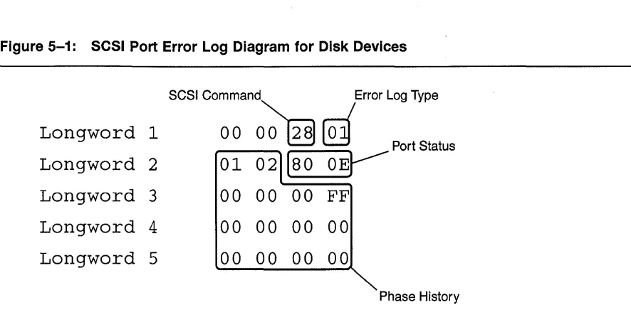
5-1 SCSI Port Error Log Diagram for Disk Devloe$ 5-2
5-2 SCSI Port Error Log Diagram for Tape Devices 5-4
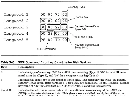
5-3 SCSI Command Error Log for Disk Example 5-6
5-4 SCSI Command Error Log Structure for Tape Deviees 5-7
5-5 Example of Compare Error Log 5-8
8-1 Internal CI Ports and DIP Switch S1 8-3
8-2 Rear of Trident 8-7
9-1 Rear view 9-1
9-2 Term Power Jumper Location 9-3
9-3 Cabling Example 9-4
9-4 SCSI Ports 9-5
9-5 Differential Daughter Card 9-6
9-6 Daughter Card Installation 9-7
9-7 DSSI Daughter Card 9-8
10-1 Front Serial Port 10-1
10-2 Rear Serial Port 10-2
10-3 Cache Module Installation 10-3
10-4 EPROM Size Jumpers 10-4
10-5 Floppy Installation 10-6
10-6 Connecting the Front Panel 10-7
10-7 Rear Serial Port Internal Connection 10-8
13-1 Rear View of Hawk Enclosure 13-1
13-2 Port 5 Configured for DSSI 13-3
13-3 Port 5 Configured for SCSI 13-4
13-4 Hawk Port 4 Configured for SCSI 13-5
13-5 Hawk Port 4 Configured for DSSI 13-6
14-1 Hawk DSSI and SCSI Ports 14-2
Contents
14-2 Hawk Port 0 14-3
14-3 Hawk Port 1 14-6
14-4 Hawk Port 2 14-9
14-5 Hawk Port 3 14-12
14-6 Hawk Port 4 14-15
14-7 Hawk Port 5 14-18
16-1 CDI-4220 Ports 16-1
16-2 CDI-4220 DSSI Port (J9) 16-3
16-3 CDI-4220 SCSI Port 16-5
17-1 CDI-4240 Components 17-1
17-2 CDI-4240 Port 0 17-3
17-3 CDI-4240 Port 1 17-6
17-4 CDI-4240 Port 2 17-9
17-5 CDI-4240 Port 3 17-11
18-1 Cache Installation 18-1
18-2 SIMM Size Selector 18-3
19-1 SC Kit Installation 19-2
19-2 SC Kit Cables 19-3
19-3 SD Kit Installation 19-4
20-1 Component Map 20-1
20-2 EPROM Jumpers 20-2
TABLES
2-1 Commands by Function 2-2
2-2 Special Editing Keys 2-4
2-3 Device Name Hierarchy 2-8
2-4 Event Log Parsing Information 2-19
2-5 Event Code Break Down 2-19
3-1 Conventions Used in this Manual 3-1
4-1 Polyport Naming Examples 4-2
5-1 SCSI Port Error Log Structure 5-3
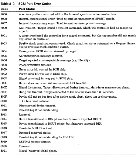
5-2 SCSI Port Error Codes 5-5
5-3 SCSI Command Error Log Structure for Disk Devices 5-6
5-4 Compare Error Log 5-9
5-5 SCSI Bus Phases 5-15
5-6 SCSI Command Hex Codes (Disk Devices) 5-15
5-7 SCSI Command Hex Codes (Tape Devices) 5-16
5-8 SCSI Sense Key Hex Codes 5-17
5-9 SCSI ASC & ASQ Hex Codes 5-18
7-1 Technical Specifications 7-2
8-1 Minimum Revision Levels 8-1
8-2 Default CI Parameters 8-4
Contents
8-3 CI Node Selection 8-5
8-4 CI Slot Count Selection 8-6
8-5 CI Node Count Selection 8-6
8-6 CI Header Length Selection 8-7
9-1 Maximum Cable Lengths 9-2
10-1 Cache Module Size 10-3
10-2 EPROM Size Selection 10-4
10-3 Reserved Jumpers 10-5
11-1 Hawk Technical Specifications 11-2
13-1 Maximum Cable Lengths 13-2
14-1 Hawk Port 0 SCSI Termination 14-4
14-2 Hawk Port 0 DSSI Termination 14-4
14-3 Hawk Port 0 SCSI Term Power 14-4
14-4 Hawk Port 0 DSSI Term Power 14-5
14-5 Port 1 SCSI Termination 14-7
14-6 Port 1 DSSI Termination 14-7
14-7 Hawk Port 1 SCSI Term Power 14-7
14-8 Hawk Port 1 DSSI Term Power 14-8
14-9 Hawk Port 2 SCSI Termination 14-10
14-10 Hawk Port 2 DSSI Termination 14-10
14-11 Hawk Port 2 SCSI Term Power 14-10
14-12 Hawk Port 2 DSSI Term Power 14-11
14-13 Hawk Port 3 SCSI Termination 14-13
14-14 Hawk Port 3 DSSI Termination 14-13
14-15 Hawk Port 3 SCSI Term Power 14-13
14-16 Hawk Port 3 DSSI Term Power 14-14
14-17 Hawk Port 4 SCSI Termination 14-16
14-18 Hawk Port 4 DSSI Termination 14-16
14-19 Hawk Port 4 SCSI Term Power 14-16
14-20 Hawk Port 4 DSSI Term Power 14-17
14-21 Hawk Port 5 SCSI Termination 14-19
14-22 Hawk Port 5 DSSI Termination 14-19
14-23 Hawk Port 5 SCSI Term Power 14-19
14-24 Hawk Port 5 DSSI Term Power 14-20
15-1 Cobra Technical Specifications 15-2
16-1 CDI-4220 Default Configuration 16-2
16-2 CDI-4220 DSSI Node 10 16-3
16-3 CDI-4220 DSSI Termination Settings 16-4
16-4 CDI-4220 DSSI Term Power 16-4
16-5 CDI-4220 SCSI 10 16-5
16-6 CDI-4220 SCSI Term Power 16-6
17-1 CDI-4240 Default Configuration 17-2
Contents
17-2 COI-4240 Port Configuration Page Reference 17-2
17-3 COI-4240 Port 0 OSSI/SCSI Selection 17-3
17-4 COI-4240 Port 0 OSSI Node 10/SCSIID 17-4
17-5 COI-4240 Port 0 Termination Settings 17-5
17-6 COI-4240 Port 0 Term Power Settings 17-5
17-7 COI-4240 Port 1 OSSI/SCSI Selection 17-6
17-8 COI-4240 Port 1 OSSI Node 10/SCSIID 17-7
17-9 COI-4240 Port 1 Termination Settings 17-8
17-10 COI-4240 Port 1 Term Power Settings 17-8
17-11 COI-4240 Port 2 SCSI 10 17-9
17-12 COI-4240 Port 2 Termination Settings 17-10
17-13 COI-4240 Port 2 Termination Power Settings 17-10
17-14 COI-4240 Port 3 SCSI 10 17-11
17-15 COI-4240 Port 3 Termination Settings 17-12
17-16 COI-4240 Port 3 Termination Power Settings 17-12
18-1 COI-4204 SIMM Specifications 18-2
18-2 COI-4204 Jumper W1 (SIMM Size) 18-3
20-1 Jumpers W1 and W2 (EPROM Size) 20-2
Chapter 1
Introduction
This manual explains the installation, configuration, and use of CMD Technology's Trident, Hawk, and Cobra storage array controllers. Part I is devot~d to the command line interface, error logs, and the front panel. These subjects apply to all three controllers. Part II covers the installation of the Trident controller. Part III covers the installation of the Hawk controller. And Part IV covers the installation of the Cobra controller.
1.1 Manual Conventions
Several chapters in this manual cover material common to all three storage array controllers. Occasionally, exceptions will have to be made for specific controllers. The manual will flag these exceptions with the following icons ...
_ Information pertaining to the Trident CIIDSSIIFDDI storage array controller.
~ Information pertaining to the Hawk CIIDSSI storage array controller.
am
Information pertaining to the Cobra DSSI storage array controller.Part I
Operating Instructions
Operating Instructions
Chapter 2
Command Line Interface
This chapter describes the command line interface (CLI) and explains how to use the CLI to perform common configuration functions. See Chapter 3 for an alphabetical listing of the complete CLI command set.
2.1
Overview
The command line interface makes it possible to configure the controller and the devices connected to it from a console or terminal. Among the tasks you may perform through the command line interface are ...
Create a stripeset
Partition a disk or stripeset
Assign a (T )MSCP unit number to a disk or tape device Set the controller's system node name
Set a DSSI or SCSI port's ID number
_ _ DSSI and SCSI port IDs on the Cobra must be set via hardware jumpers.
Table 2-1 lists the CLI command set organized by function.
Operating Instructions
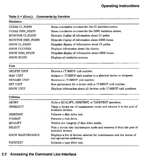
Table 2-1: Commands by Function
Controller FACTORY QUIESCE RESTART RESUME SETCI SET CONTROLLER SET LOG SET PORT SHOW CONTROLLER WRITE Device AUTOCONFIG
CREATE DISK
CREATE TAPE
DELETE DISK DELETE TAPE RESET SCSCBUS SET DISK SHOW DEVICES SHOW DISK SHOW TAPE Miscellaneous HELP QUIT SHOW ALL
2-2 Command Line Interface
Resets controller parameters to factory default settings.
Temporarily halts activity on one or more SCSI buses for the purpose of swapping a device.
Restarts the controller, forcing configuration parameters stored in non-volatile memory to become current.
Resumes activity on one or more SCSI buses after a QUIESCE.
Sets the controller's CI parameters. Not applicable to the Cobra.
Sets a number of controller-specific parameters.
Filters error and event messages displayed on the console terminal.
Sets· port-specific parameters.
Displays information about controller configuration.
Writes parameter settings held in the editing buffer to the floppy diskette. Not applicable to the Cobra.
Scans all SCSI buses and associates a unique physical name to each device found.
Associates a unique physical name to a disk drive.
Associates a unique physical name to a tape drive.
Deletes. a physical name previously associated with a disk drive.
Deletes a physical name previously associated with a tape drive.
Resets one or more SCSI buses. Devices will go into MOUNT VERIFY.
Creates up to eight partitions on a disk drive.
Displays a listing of disk and tape devices previously identified by the AUTOCONFIG, CREATE DISK, or CREATE TAPE commands.
Displays a listing of disk devices previously identified by the AUTOCONFIG or CREATE DISK commands.
Displays a listing of tape devices previously identified by the AUTOCONFIG or CREATE TAPE commands.
Displays a syntax guide for all CLI commands.
Quits the command line interface and returns to the host when access-ing through DUP.
Operating Instructions
Table 2-1 (Cont.): Commands by Function
Statistics CLEAR CCSTATS CLEAR DSSCSTATS MONITOR CCSTATS MONITOR DSSCSTATS SHOW CCSTATS SHOW CLUSTER SHOW DSSCSTATS SHOWSTATS Unit DELETE UNIT MAP UNIT
RENAME UNIT
SET UNIT SHOW UNIT Utilities ABORT DESELECT DISKTEST FORMAT QUALIFY SELECT SHOW MAINTENANCE TAPETEST
Zeros cumulative counters for the CI statistics screen.
Zeros cumulative counters for the DSSI statistics screen.
Dynamic display of information about CI paths.
Dynamic display of information about DSSI buses.
Shapshot display of information about CI paths.
Displays information about the cluster.
Shapshot display of information about DSSI buses.
Displays all statistics screens.
Deletes a (T )MSCP unit number.
Assigns a (T )MSCP unit number to a physical device or stripeset. Renames a (T )MSCP unit number.
Sets parameters for a device with a (T )MSCP unit number.
Displays information about all devices with (T )MSCP unit numbers.
Halts a QUALIFY, DISKTEST, or TAPETEST operation.
Takes a device out of maintenance mode and returns it to the pool of available devices.
Initiates a disk drive test.
Formats a disk drive.
Veri:6.es the integrity of disk drive media.
Puts a device into maintenance mode and removes it from the pool of available devices.
Displays a list of devices selected for maintenance and the status of any operations underway.
Initiates a tape drive test.
2.2 Accessing the Command Line Interface
There are two ways to access the command line interface: from the Open VMS prompt and from the controller's serial port. This section will describe the steps necessary to access the command line interface from the Open VMS prompt. See Parts II through IV for a discussion of controller serial ports.
[image:19.615.73.557.62.607.2]Operating Instructions
2.2.1 OpenVMS Prompt
Follow these steps to connect to DUP from the OpenVMS prompt.
o
If you are working on a terminal connected to a VAX system, issue the following command to connect to the DUP device:$ MC SYSGEN CONNECT FYAO/NOADAPTER
If you are working on a terminal connected to an AXP system, issue the following com-mand to connect to the DUP device:
$MC SYSMAN 10 CONNECT FYAO/NOADAPTER/DR1VER=SYS$FYDR1VER
f) Once you have connected the DUP device, you can access the controller's DUP programs by issuing the following command:
$ SET HOST/DUP/TASK=PARAMS/SERVER=MSCP$DUP n
Replace the variable n at the end of the command line with the nodename of the controller.
NOTE
Type QUIT at the command prompt to exit a DUP session and return to the host.
The QUIT command,has no effect when you are connected to the serial port.
2.3 Keyboard Shortcuts
When you are entering a command in the command line interface, you may use the delete key to delete a character, and the left and right arrow keys to move one character to the left or right. In addition, you may use the special keys listed in Table 2-2 to erase the entire line or recall commands from the command stack.
Table 2-2: Special Editing Keys
Key
Ctrl-U
Up Arrow Down Arrow
Function
Line erase
Recall previous command
Recall next command
2.4 Controller Commands
Most of the controller commands are intended to be used during the installation and initial configuration of the controller. They are not limited to this purpose, however, and may be used whenever you wish to modify the configuration of the controller. Other controller com-mands such as QUIESCE, RESTART, and RESUME are intended to be used during normal operation.
Operating Instructions
2.4.1 Set Up Commands
A typical eLI session during the course of an initial controller installation might go as fol-lows ...
Use the SET CONTROLLER command to set parameters that govern the controller's
relation-ship with the cluster and the storage devices connected to, the controller. NODE> SET CONTROLLER /SYSTEM_ID=180155
NODE> SET CONTROLLER /NODENAME=BIFF
The SYSTEM_ID and NODENAME qualifiers set the ses system ID and node name of the
controller. These parameters must be unique among all nodes in the cluster. There is no need to set the system ID if the default value of the qualifier (131072 plus the serial number of the controller) does not conflict with any other node in the cluster.
CAUTION
In a redundant controller configuration, port 0 on controller #1 must be connected to port 0 on controller #2, port 1 on controller #1 must be connected to port 1 on controller #2, and so on. Futhermore, both controllers must have the same disk and tape allocation class values (assigned with the SET CONTROLLER command).
The / REDUNDANT qualifier of the SET CONTROLLER command must be turned
"ON." And the / POWER_ON _RESET qualifier of the SET PORT command must be
turned "OFF" for all common SCSI buses. NODE> SET CONTROLLER /DISK_ALCS=4
NODE> SET CONTROLLER /TAPE_ALCS=4 NODE> SET CONTROLLER /REDUNDANT=ON
SET CONTROLLER also takes the following qualifiers.
NODE> SET CONTROLLER /MAX_HOSTS=32 NODE> SET CONTROLLER /DEVICE_TYPE=RA NODE> SET CONTROLLER /SPINUPDELAY=5
The / MAX_HOSTS qualifier may be set to any integer value between 1 and 32. The default
is 32. The / DEVICE_TYPE qualifier determines how devices connected to the controller will
be reported to the host. You may select from RF, RA, HS. The / SPINUPDELAY qualifier sets
the spin up interval between disk drives on the controller's buses. See Chapter 3 for more information about these qualifiers.
Another step in the initial configuration of a controller is the SET PORT command. This
command enables or disables a port and determines whether the controller issues a reset to the SCSI buses at power on.
On the Trident and Hawk controllers, the SET PORT command sets the SCSI ID
or DSSI node ID of each port on the controller. It also identifies the port as SCSI, DSSI or inactive. (On the Trident, you must have a DSSI daughter card and the appropriate DSSI license to switch a SCSI port to DSS!.)
The Cobra controller does not support the SET PORT qualifiers for setting the SCSI
or DSSI ID, or establishing a port as SCSI or DSS!. You must set jumpers on the board to perform these functions.
Operating Instructions
The following example applies to either the Trident or Hawk. The Cobra does not support the
/ TYPE and /ID qualifiers.
NODE> SET PORT 5 /ENABLE/TYPE=DSSI NODE> SET PORT 5 /ENABLE/ID=2 NODE> SET PORT 0 /ENABLE/ID=7 NODE> SET PORT 1 /ENABLE/ID=7 NODE> SET PORT 2 /ENABLE/ID=7 NODE> SET PORT 3 /ENABLE/ID=7 NODE> SET PORT 4 /ENABLE/ID=7
Each SCSI port on the controller must be set to SCSI ID 7, unless you have a dual controller configuration, in which case you would set one controller's SCSI ports to ID 7 and the other's ports to ID 6.
You may view your controller configuration at any time by entering the SHOW CONTROLLER command.
TRIDNT> SHOW CONTROLLER
Controller TRIDNT Serial No.: 0
Date/Time: 27-JUL-1995 13:41:49 Processor DRAM size: 4 MB Device Type = HS Redundant Mode = OFF Rev A Compatible OFF
Firmware Revision: BT60 uptime: 0 DAYS 00:07:11 Processor F~ee Pool: 235 KB Spinup Delay 5 Seconds polyport OFF Type RF72 SCS Parameters
Nodename: TRIDNT DISK_ALCS: 2 MAX_HOSTS: 32
System ID: 909090 TAPE_ALCS: 5 DATREQ_PR: HIGH Cache
16 MB read cache Ports
Port 0: SCSI, id= 7, power_ on -reset=ON Port 1: SCSI, id= 7, power_on_ reset=ON Port 2: SCSI, id= 7, power_on_ reset=ON Port 3: SCSI, id= 7, power_ on -reset=ON Port 4 : SCSI, id= 7, power_on_ reset=ON Port 5: DSSI, id= 2
NOTE
If you have a configuration with a redundant pair of controllers, be sure to set
/ POWER_ON _RESET to "OFF" for those ports with shared SCSI buses. In a single controller configuration, you should set / POWER_ON _RESET to "ON."
The / POLYPORT qualifier permits the system administrator to achieve a degree of load balancing between two CMD controller host paths. It is intended for those users who wish to fine tune the performance of the controller and is not essential to the operation of the controller. For more information about Polyport, see Chapter 4.
Since Polyport requires two host ports, this feature does not apply to the CDI-4220 model, which has only one DSSI host port.
Operating Instructions
2.4.2 Hot Swapping SCSI Devices
The controller supports the hot swapping of SCSI devices. Since the removal of a SCSI bus can disrupt signal activity on the bus and possibly cause data corruption, you should make sure that the bus is quiet before performing the hot swap. This can be done with the QUIESCE
command.
For example, if you need to replace a disk drive on bus 0, you would first halt activity on the bus by entering the following command.
NODE> QUIESCE 0
Once you have completed the swap, open up the bus for activity again by entering the
RESUME command.
NODE> RESUME 0
2.4.3 Saving Parameter Changes
The TridentlHawk and Cobra controllers differ in the way they handle the saving of parameter changes.
Parameter changes will be lost when you power down or RESTART the controller,
unless you WRITE them to the floppy diskette.
All parameter changes are saved immediately in non-volatile memory. The WRITE
command is not available, nor is it needed, on the Cobra.
All parameter changes, except those you make with the SET UNIT command, require a
controller RESTART to become effective. Changes made with the SET UNIT and RENAME UNIT commands take effect immediately, but on the Trident or Hawk controllers, you must WRITE the new values to the floppy diskette to make them permanent.
The following example shows the steps necessary to change a Trident or Hawk controller's node name and then make the change effective.
NODE> SET CONTROLLER /NODENAME=BOB NODE> WRITE
NODE> RESTART BOB>
CAUTION
Each time you power on or reset the controller, it loads its firmware and configuration data from the floppy diskette. The controller will not operate unless the boot up diskette is inserted in the floppy drive. If you make configuration changes that you wish to remain in effect after a controller RESTART, you must WRITE them to the floppy diskette. If you RESTART the controller without first saving any configuration changes,
the changes will be lost and the l~st saved configuration environment will be loaded.
Operating Instructions
2.4.4 Restoring Factory Default Settings
The FACTORY command restores all configuration parameters to their factory default settings.
This command is useful when you have made numerous parameter changes that did not produce the controller behavior that you intended. The FACTORY command lets you start again from a clean slate.
2.5 Device Naming Scheme
A discussion of the Device, Unit, and Stripeset commands must be predicated on an un-derstanding of the command line interface's device naming scheme, which is based on the three-tiered hierarchy outlined in Table 2-3.
Table 2-3: Device Name Hierarchy
Levell Level 2 Level 3 Type Physical Name Logical Name (T)MSCP Device Name Format Dpil Tpil
SO, Sl, ... S15
DUA1000,
DIA4120, MUA200
Purpose
Identifies a device within the command line interpreter. Name is determined by the type of device and the device's physical installation. Disk devices start with "D." Tape devices start with "T." The remainder of the name is the port "p," SCSI ID "i," and LUN "I" of the device.
A logical placeholder used to identify a stripeset within the command line inter-preter.
The name by which a device, whether it be a disk, tape or stripe set, is known to the host.
Device commands operate on level 1. Stripe set commands operate on level 2, and unit com-mands operate on level 3. Every device must have a physical name. If you choose to create a stripeset, the stripeset will encompass one or more disk drives identified by their physical device names. Finally, to make any device or logical stripeset available to the host, you must map it to a (T )MSCP device name.
2.6 Device Commands
The controller does not automatically scan its SCSI buses to identify new devices. Instead, it relies on specific instructions from the operator via the command line interface to identify new devices. These instructions come in the form of the device commands AUTOCONFIG,
CREATE DISK, and CREATE TAPE.
If you are adding many disk and tape devices to the controller at the same time, the easi-est way to name the devices is to use the AUTOCONFIG command. This command scans all the controller's SCSI buses and creates physical names for every device it finds. The
AUTOCONFIG command takes no parameters or qualifiers:
Operating Instructions
NODE> AUTOCONFIG
NOTE
AUTOCONFIG will ignore any ports (and the devices on them) that have not
previously been enabled and defined as SCSI. When you enable a port with the SET
PORT p /ENABLE command, you must WRITE the new value to the non-volatile
memory and RESTART the controller for the change to take effect.
Alternatively, you may use the CREATE DISK and CREATE TAPE commands to create physical names for specific devices. To create names for a tape device connected to port 0, SCSI ID 3, LUN 0, and a disk device connected to port 2, SCSI ID 0, LUN 0, you would type the following commands.
NODE> CREATE TAPE T030 NODE> CREATE DISK D200
You may combine several devices of the same type on a single command line. For instance, to create names for a string of six devices on Port 3, you might enter this command.
NODE> CREATE DISK D300 D310 D320 D330 D340 D350
Once you create a physical device name, you can later delete the name with the DELETE
DISK and DELETE TAPE commands. You might wish to delete a physical device name if you
decide to remove a device or replace one type of device (either disk or tape) with another type.
NODE> DELETE DISK D310 NODE> DELETE TAPE T030
You may get a display of all physical device names with the SHOW commands. Use SHOW DEVICES to list disks, tapes, stripesets, and mapped units. Or narrow the output of the display with either SHOW DISK or SHOW TAPE. The "Pcnt" (Partition Count) column gives the number of partitions created on the device.
NODE> show disk
Name Pcnt Used by Type Inquiry Data Device Attributes
D130 1 DISK DEC Rz26 392A Sync TagQ D160 4 DISK DEC RZ28 D41C Sync TagQ D150 4 DISK DEC RZ28 D41C Sync TagQ D140 1 DISK Quantum XP32150 556A Sync TagQ Dll0 1 DISK DEC RZ26 392A Sync TagQ D120 1 DISK Quantum XP32150 556A Sync TagQ
2.6.1
Disk Drive Partitioning
With the SET DISK command, you may divide a disk drive into up to eight partitions. When mapped to an MSCP device name, each of these partitions will be seen by the host as a
separate disk drive. The following example divides the disk drive on port 1, SCSI ID 5, LUN
°
into three partitions.NODE> SET DISK D150 /PARTITIONS=3
Operating Instructions
2.6.2 SCSI Bus Resets
If you believe that a SCSI bus is hung, you may reset it with the RESET SCSI_B US command. The following example resets SCSI bus 4. When you issue a SCSI bus reset, all devices on that bus will go into MOUNT VERIFY.
NODE> RESET SCSI_BUS 4
2.7 Stripeset Commands
With the stripeset commands, you can effectively transform several disk drives into a single drive. This can produce dramatic improvements in I/O performance. For write operations, the controller splits data from the host into smaller chunks and writes each chunk in parallel to the drives in the stripeset. The opposite occurs for read operations: the controller reads the striped data in parallel from the stripeset and passes the reconstituted data to the host.
CAUTION
The controller's stripesets are based on the RAID 0 model. This means that the stripe set has no redundancy and no way of recovering from a drive failure. If a drive fails in a stripeset, all data, including the data on the surviving members of the stripeset, will be lost. RAID 0 is designed for the sole purpose of enhancing performance and offers no data security features. You should back up the data on a stripe set, just as you would back up data on a single disk drive.
The first step in the creation of a stripeset is the creation of a logical name for the stripeset. This is done with the CREATE STRIPESET command. For instance, to create the logical stripeset name "SI," you would enter ...
NODE> CREATE STRIPESET 81
The next step is to assign disk drives to the stripe set. Refer to the disk drives by their physical names, as in the following example ...
NODE> ADD STRIPE8ET S1 D120 D220 D320 D420 D520
Once you have assigned disk drives to the stripeset, you must initialize it. This is the process by which the controller reserves a portion of each disk, where it stores special configuration data unique to that stripeset.
The CHUNKSIZE qualifier specifies how much data will be written to each drive on each stripe. Each CHUNKSIZE unit represents 4 kilobytes of data. Thus, a CHUNKSIZE of 4 would mean that each drive in the stripeset would receive 16 kilobytes of data for each stripe written. By adjusting the CHUNKSIZE qualifier, you can optimize the efficiency of the stripeset. If the chunksize is too large, some drives in the stripeset will work harder than others, and you lose the benefit of parallel data transfers. If the chunksize is too small, the controller will have to loop through more stripes than necessary to complete the write.
NODE> INITIALIZE STRIPE8ET 81 /CHUNK8IZE=4
If you wish, you may partition the stripeset with the SET STRIPESET command. Up to eight partitions are allowed.
NODE> SET 8TRIPE8ET 81 /PARTITION8=4
Operating Instructions
To make the stripeset available to the cluster, you must map the stripeset to an MSCP device name. This is done with the MAP UNIT command, which is covered in Section 2.8, Unit
Commands.
2.7.1
Other Stripeset Commands
2.8
You may delete a logical stripeset name with the DELETE STRIPESET command. If the
stripeset is mapped to an MSCP device name, the controller will not let you delete the stripeset name. First use DELETE UNIT to delete the MSCP device name, then use DELETE STRIPESET.
NODE> DELETE STRIPESET so
The SHOW STRIPESETS command displays a list of all your stripesets. In the first column
is the logical stripeset name. The second column contains the number of partitions associated with that stripeset name. The "Used by" column identifies the MSCP device name to which the stripeset or stripeset partition is mapped. The fourth column lists the chunksize. And the last column identifies the physical devices encompassed by the stripeset.
NODE> SHOW STRIPESETS
Name Pent Used by Chunksize Members
so 1 DUA200 4 D050 D040 D030 D020 DOlO DOOO Sl 2 DUA210 (1) 4 D150 D140 D130 D120 D110 D100 Sl 2 DUA215 (2)
S2 1 DUA220 4 D240 D230 D220 D210 D200 S3 1 DUA230 4 D340 D330 D320 D310 D300 S4 1 DUA240 4 D440 D430 D420 D410 D400 S5 1 DUA250 4 D540 D530 D520 D510 D500
Unit Commands
The unit commands manage MSCP and TMSCP device names for your devices, stripesets, and partitions. The (T)MSCP device name is the name by which a device is known to the host. You cannot give a device a (T)MSCP device name without first giving it a physical name. This applies to stripesets and partitions as well as disk and tape devices, since they all appear as single devices· to the host.
Use the MAP UNIT command to assign a (T)MSCP device name to a disk, tape, stripeset
or partition. Device names for disk drives, stripesets, and partitions must begin with DU or DI. Tape drive device names must begin with MU. The letter "A" should be the third letter in the prefix to conform with the device naming rules of VMS Version 5.3 and above. You may append any number from 0 to 9999, as long as the resulting name is unique among all devices in the cluster.
NODE> MAP UNIT D220 DUA2000 NODE> MAP UNIT T140 MUA1001
NODE> MAP UNIT SO /PARTITION=l DUA2020 NODE> MAP UNIT sO /PARTITION=2 DUA2021
Operating Instructions
You can delete a device name with the DELETE UNIT command, and change a device name with the RENAME UNIT command.
NODE> DELETE UNIT DUA2000
NODE> RENAME UNIT DUA2020 DUA3020
2.8.1
Setting Unit Parameters
With the SET UNIT command, you can set a number of unit parameters. The following exam-ple shows how to set a few parameters. For a full list and description of these parameters, see Chapter 3, Command Dictionary.
NODE> SET UNIT DUA3020 /WRPROT/NODISCONNECT/SYNC=10 NODE> SET UNIT MUA1010 /SHORT_TMARK/SYNC=S/NOTAGGED
2.8.2 Show Unit Command
The SHOW UNIT lists all device names and selected information about each one. The number in parentheses under the "Member" heading identifies which partition of the disk drive or stripeset is mapped to the unit.
NODE> SHOW UNIT
Name Member Status
DUA200
so
(2) ONLINEDUA210 Sl (1) ONLINE
DUA220 S2 (2) ONLINE
2.9 Utility Commands
Host
NODE
NODE
NODE
Set-members/Modifiers
DOSO D040 D030 D020 DOlO DOOO
online, cache, disconnect, immediate, tagging, truncate,
spindown, sync_rate=10
D1S0 D140 D130 D120 D110 D100
online, cache, disconnect, immediate, tagging, truncate,
spindown,sync_rate=10
D240 D230 D220 D210 D200
online, cache, disconnect, immediate, tagging, truncate,
spindown, sync_rate=10
The command line interface offers utilities for formatting and qualifying disk drives, and testing the ability of the controller to read and write to a particular disk or tape drive.
Operating Instructions
2.9.1
Select
To perform a utility function on a device, you must first SELECT the device. This removes the device from the pool of devices available to the cluster and puts the device into maintenance mode. The argument of the SELECT command must be a physical device number.
NODE> SELECT DIOO
Once you have selected a device you may FORMAT, QUALIFY, TAPETEST, or DISKTEST it.
TAPETEST applies only to tape devices, and DISKTEST applies only to disk devices.
2.9.2 Format
The FORMAT command will overwrite any data on the disk. (Most new SCSI disk drives are
formatted at the factory prior to shipment.)
NODE> SELECT DIOO NODE> FORMAT DIOO
FORMAT will display a console message when the operation is completed. You may
periodi-cally issue the SHOW MAINTENANCE command to check on the status of the format. It is a good practice to run one or more QUALIFY passes on the drive after a format.
2.9.3 Qualify
QUALIFY verifies the integrity of the drive's media. Without the /WRITE qualifier, QUALIFY
will not alter any data stored on the disk. With the / WRITE qualifier, the command will overwrite any data on the disk. The /WRITE qualifier must be used whenever you qualify a brand new disk that contains no data. QUALIFY will continue indefinitely until halted with
the ABORT command.
NODE> SELECT D230
NODE> QUALIFY /WRITE D230 NODE> ABORT D230
2.9.4 Disktest
DISKTEST exercises the selected drive and corrects any media errors encounters. During
a DISKTEST / WRITE operation, the controller writes to randomly selected logical blocks on the device and then reads and verifies the data. If the device you want to test already contains data, omit the / WRITE qualifier, and DISKTEST will read from randomly selected logical blocks. For newly formatted devices, you must must use the / WRITE qualifier, or else
DISKTEST will have no data to read.
NODE> SELECT D230
NODE> DISKTEST /WRITE D3I0 NODE> ABORT D3I0
Operating Instructions
2.9.5 Tapetest
TAPETEST exercises the selected tape device by writing, rewinding, and reading each section of tape, up to but not including filemarks. The block size for the initial pass is 32 kilobytes. This is· halved on each successive write/rewind/read operation. The test restarts when the block size reaches 1 kilobyte.
NODE> SELECT D230 NODE> TAPETEST Tl50 NODE> ABORT Tl50
2.9.6 Deselect
When you are finished with a utility operation and wish to return a device to the pool of available devices, use the'DESELECT. This will take the device out of maintenance mode.
NODE> DESELECT D230
2.9.7 Show Maintenance
You may view a list of devices under maintenance and the status of all utility operations by entering the SHOW MAINTENANCE command.
NODE> show maintenance
Device Test Flags Status
Dl30 QUALIFY RO Active LBN = OxOOOO4500
Dl60 RO Idle
Dl50 FORMAT RW Active
Dl40 QUALIFY RW Active LBN = OxOOOOlOcO DllO DISKTEST RO Active LBN = OxOOlc98l6 Dl20 DISKTEST RW Active LBN = OxO~384e08
The Device column lists all the devices currently selected for maintenance. The devices are identified by their physical names. The Test column indicates the maintenance operation cur-rently underway for each listed device. A blank field indicates that no operation is underway for that device.
The Flags column indicates whether the maintenance operation is Read-Only (RO) or Destructive (RW). The FORMAT and TAPETEST are always destructive, meaning that these operations write to the media. QUALIFY and DISKTEST are Read-Only, unless you specify the /WRITE qualifier which makes each operation destructive. In addition to RO and RW, the Flags column may also indicate that a test is in the process of being aborted or that a bad block was detected and is in the process of being replaced. These indicators are transient and may rarely be visible to the user.
When a device is currently undergoing a FORMAT or TAPETEST, the Status field for the device will show "Active." For a DISKTEST or QUALIFY operation, the Status field will show the progress of the operation by displaying a snapshot of the current logical block number being processed.
If you decided to abort a maintenance operation, the "Test aborted by user" message will be displayed in the Status field. Note that FORMAT operations cannot be aborted and will remain active until completed.
Operating Instructions
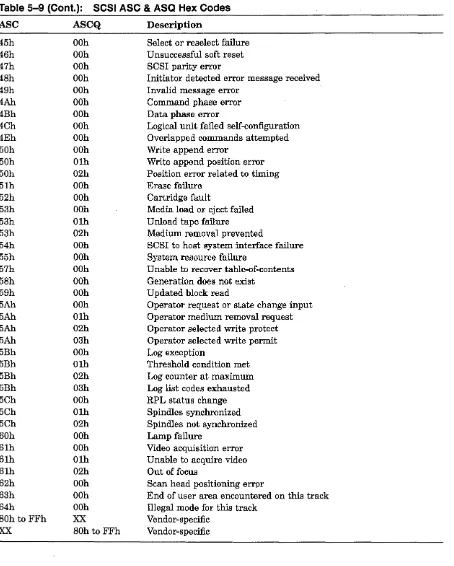
If the controller encounters a SCSI target error during a maintenance operation, it will display the error code in the Status field. The target error display takes the following format:
Idle CHKCOND xxh:yyh:zzh SCSI-OP
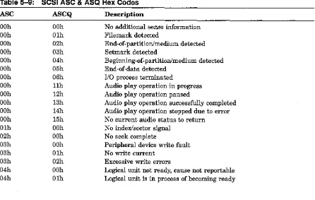
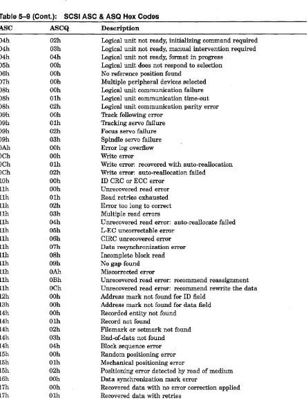
"CHKCOND" refers to the SCSI check condition status. The variable "xxh" will be the SCSI sense key value (see Table 5-8). The variable "yyh" refers to the SCSI additional sense code (ASC) value, and "zzh" refers to the SCSI additional sense code qualifier (ASCQ) value. See Table 5-9 for a list of ASC and ASCQ codes. "SCSI-OP" will be replaced with the SCSI operation that was underway when the error occurred.
If the controller encounters a SCSI port error code during a maintenance operation, it will display the following information in the Status field.
Idle SCSI Port Error OxXXXX
A complete list of SCSI port error codes may be found in Section 5.1.1.3.
2.10 Common Cli Task Examples
Many configuration tasks require CLI commands from more than one category. This section contains examples of common eLI tasks and shows how some of these tasks make use of commands from various categories.
2.10.1 Configuring the Controller
Typically when you first install the controller, you will need to assign a node name to the controller and set its allocation class. The SET CONTROLLER command allows you to set
these parameters. In the following example, we will be changing the node name to "BLUE" and the disk and tape allocation classes to "4."
Example 2-1: Set Controller Example
NODE> SET CONTROLLER /NODENAME=BLUE NODE> SET CONTROLLER /DISK_ALCS=4 NODE> SET CONTROLLER /TAPE_ALCS=4
You may combine two or more qualifiers in a single command.
Example 2-2: SET CONTROLLER Example
NODE> SET CONTROLLER /DISK_ALCS=4/TAPE_ALCS=4
See Chapter 3 for a complete description of the SET CONTROLLER syntax and qualifiers.
Operating Instructions
2.10.2 Configuring a Port
Trident and Hawk controllers have six DSSIISCSI ports, numbered from 0 to 5. Depending on the features of your particular model, you may change a DSSI port to a SCSI port, or vice versa.
The Cobra's DSSI and SCSI ports must be configured with the jumpers on the con-troller board. The only SET PORT qualifiers that apply to the Cobra are /ENABLE,
/DISABLE, and /POWER_ON_RESET.
This example shows how to enable port 5 on a Trident or Hawk controller, make it a SCSI port, and assign SCSI ID 7 to it.
Example 2-3: SET PORT Example
NODE> SET PORT 5 /ENABLE/TYPE=SCSI/ID=7
See Chapter 3 for a complete description of the SET PORT syntax and qualifiers.
2.10.3 Naming and Mapping Devices
Example 2-4 shows how to assign physical names to a pair of disk drives and one tape drive. The disk drives are on port 2, SCSI IDs 2 and 3. The tape drive is on port 1, SCSI ID 4.
Example 2-4: Device Naming Example
NODE> CREATE DISK D220, D230
Creating Type Inquiry Data
D220 D230
DISK DEC DISK DEC
NODE> CREATE TAPE T140
DSP3107 DSP3107
Creating Type Inquiry Data
440C 440C
T140 TAPE Archive python 25501-XXX
NODE> MAP UNIT D220 DUA1220
NODE> MAP UNIT D230 DUA1230
NODE> MAP UNIT T140 MUAl140
Device Attributes
Sync TagQue Sync TagQue
Device Attributes
NoTagQue
2.10.4 Creating and Mapping a Disk Partition
Example 2-5 shows how to split a disk on Port 2, SCSI ID 2, LUN 0 into three partitions and then map the partitions to MSCP device names.
Example 2-5: Creating and Mapping Disk Partitions
NODE> CREATE DISK D220
Creating Type Inquiry Data
D220 DISK DEC DSP3107 440C
NODE> SET DISK D220 /PARTITIONS=3
NODE> MAP UNIT D220 /PARTITION=l DUA1220
NODE> MAP UNIT D220 /PARTITION=2 DUA1221
NODE> MAP UNIT D220 /PARTITION=3 DUA1222
2.10.5 Configuring a Disk Device
Device Attributes
Sync TagQue
Operating Instructions
Use the SET UNIT command to configure the relationship between the controller and a specific disk device. The following example shows how to turn on write protection and tagged command queuing and set the synchronous transfer rate to 10MB/sec. for device DUA2020. While each command is on a separate line in this example, you may combine all the qualifers on one command line, if you wish.
Example 2-6: SET UNIT Example
NODE> SET UNIT DUA2020 /WRPROT NODE> SET UNIT DUA2020 /TAGGING NODE> SET UNIT DUA2020 /SYNC=10
See Chapter 3 for more information about the SET UNIT command.
NOTE
The SET UNIT command also configures tape devices, but a different set of quali-fiers apply. These qualiquali-fiers are described in Chapter 3.
2.10.6 Creating a Stripeset
This example shows how to add four disk drives, bind them into a stripeset, and give the stripeset an MSCP device name.
NOTE
For best performance, connect each member of
a
stripeset to a separate SCSI bus. This permits each disk drive to be accessed in parallel and the full bandwidth of each bus to be used ..Operati ng Instructions
Example 2-7: Stripeset Creation Example
NODE> CREATE DISK DOlO D130 D200 D340
Creating Type Inquiry Data
DOlO Dl30 D200 D340
DISK DEC DISK DEC DISK DEC DISK DEC
NODE> CREATE STRIPESET SO
DSP3l07 DSP3107 DSP3107 DSP3l07 440C 440C 440C 440C
NODE> ADD STRIPESET SO DOlO D130 D200 D340
NODE> INITIALIZE STRIPESET SO
NODE> MAP UNIT SO DUA1020
Device Attributes Sync TagQue Sync TagQue Sync TagQue Sync TagQue
2.10.7 Creating and Partitioning a Stripeset
This example shows how to add four disk drives, bind them into a stripeset, split the stripeset into two partitions, and give each partition an MSCP device name.
Example 2-8: Stripeset Creation and Partitioning Example
NODE> CREATE DISK DOlO D130 D200 D340
Creating Type Inquiry Data
DOlO D130 D200 D340
DISK DEC DISK DEC DISK DEC DISK DEC
NODE> CREATE STRIPESET SO
DSP3107 DSP3107 DSP3107 DSP3107 440C 440C 440C 440C
NODE> ADD STRIPESET SO DOlO D130 D200 D340
NODE> INITIALIZE STRIPESET SO
NODE> SET STRIPESET SO /PARTITIONS=2
NODE> MAP UNIT SO /PARTITION=l DUA1020
NODE> MAP UNIT SO /PARTITION=2 DUAI021
2.11
Event Logs
Device Attributes Sync TagQue Sync TagQue Sync Tag Que Sync TagQue
The command line interface includes an event log, which immediately posts a message on the terminal whenever a defined event occurs. Table 2-4 lists the information categories reported in the event log and each category's position in the event log line.
Table 2-4: Event Log Parsing Information
Category Position
Date Stamp Characters 1 to 9
Time Stamp Characters 11 to 18
Unique Log Event Code
Finnware Process
Textual Event Description
Characters 20 to 23
Characters 25 to 31
Characters 35 to 79
Operating Instructions
The controller does not have its own clock, so the date and time stamp is based on the host's internal clock. Events logged before the controller has connected to the host will carry the default stamp of "OI-JAN-I990 00:00:00."
Like VMS DeL messages, event log messages do not interfere with input on the command line.
The following example shows some sample event log entries:
Example 2-9: Event Log Example
30-MAY-95 12:24:45 3A05 SCSIDR5 30-MAY-95 12:24:45 5300 MSCP$DI 30-MAY-95 12:24:45 380B RIO$31 30-MAY-95 12:24:45 5300 MSCP$DI 30-MAY-95 12:24:45 3806 RIO$31
2.11.1 Event Codes
Reset Detected on SCSI Port 5 unit DUA2020 Onlined by BARNEY
PIL=220: Test-Unit-Ready Command Failed Log Buffer Full, 4 Messages Lost
PIL=220: Sts=02h,Key=2h,ASC=40h,Q=83h
Event codes are reported as I6-bit hexadecimal numbers. Table 2-5 gives a break down (starting from the most significant bit) of the event code format.
Table 2-5: Event Code Break Down
Bits Description
15-13 The importance or severity of the event (i.e. Fatal, Warning, Infonnational)
12-8 The internal finnware sub-system that reported the event log
7 -0 The unique event code for the event
Operating Instructions
Chapter 3
Command Dictionary
,3.1
Conventions
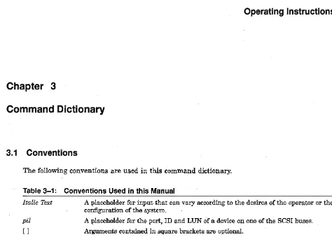
[image:37.615.67.541.59.398.2]The following conventions are used in this command dictionary.
Table 3-1: Conventions Used in this Manual
Italic Text
pil
[ ]
A placeholder for input that can vary according to the desires of the operator or the configuration of the system.
A placeholder for the port, ID and LUN of a device on one of the SCSI buses.
Arguments contained in square brackets are optional.
A horizontal ellipsis indicates that the preceding argument may be repeated one or more times.
ABORT
ABORT
Ends a utility operation.
Format
ABORT
0 / Tpi/
Parameters
DITpi/
Specifies the physical name of the device, where D stands for disk, T stands for tape, and pil stands for the port, SCSI ID, and LUN of the device.
Description
The ABORT command terminates a QUALIFY, DISKTEST, or TAPETEST operation. These
operations normally run indefinitely until halted with the ABORT command or by shutting off power to the controller.
ADD STRIPESET
Groups a set of disk drives under a logical stripeset name.
Format
ADD STRIPESET
Sx Opi/ [Opi/ .. ·
J
Parameters
Sx
ADD STRIPESET
Specifies the logical name of the stripeset to which the disk drives will be assigned. Refer to stripesets by their logical names, which are assigned by the CREATE STRIPESET command.
Dpil [Dpil ...
J
Specifies one or more disk drives to be grouped in a stripeset. The disk drives are referenced by their physical names, not their MSCP device names. Refer to disk drives by their physical names, which are created by the AUTOCONFIG, and CREATE DISK commands. (Use the
CREATE TAPE command to assign a physical device name to a tape drive.) Separate the disk
drive names with spaces.
A stripeset may contain as many as 16 disk drives. The controller will recognize a one-drive stripeset, but in practice you should include at least two drives in each stripeset.
The ADD STRIPESET command is cumulative. The specified disk drives will be added to any
drives already assigned to the stripeset.
Description
Groups a collection of disk drives under a logical stripeset name. To complete the creation of the stripeset, you must run the INITIALIZE STRIPESET command and then run MAP UNIT
to give the stripeset an MSCP device name and make it available to the operating system.
Examples
1. NODE> ADD STRIPESET S1 D100 D110 D240 D250 D310
Assigns the disk drives with physical names DI00, DII0, D240, D250, and D310 to the logical stripeset name SI.
2. NODE> ADD STRIPESET S1 D100 D110 NODE> ADD STRIPESET S1 D240 D250 D310
Since the ADD STRIPESET command is cumlative, the two commands shown in this example achieve the same result as the single command in example 1.
AUTOCONFIG
AUTOCONFIG
Scans the SCSI bus connected to the controller and assigns physical names to the devices found.
Format
AUTOCONFIG
Parameters
None.
Qualifiers
fLOG
Displays device names as they are created. Without the / LOG qualifier, AUTOCONFIG will name all devices and display no messages in the process.
Description
The controller does not automatically scan its SCSI buses for new devices. Instead it relies on the operator to identify new devices. This can be done individually with the CREATE
DISK and CREATE TAPE commands, or for all connected devices with the AUTOCONFIG
command.
NOTE
,AUTOCONFIG will ignore any ports (and the devices on them) that have not previously been enabled and defined as SCSI or DSSI. When you enable a port with the SET PORT p / ENABLE command, you must WRITE the new value to the controller's non-volatile memory and RESTART the controller for the change to take effect.
CLEAR CI_STATS
CLEAR CI_STATS
Format
Resets CI statistics counters to zero. These counters apply to the MONITOR CI_
STATS, SHOW CI_STATS and SHOW ALL commands. This command does not
apply to the Cobra.
CLEAR CI_STATS
Parameters
None
CLEAR DSSI_STATS
CLEAR DSSI_STATS
Resets DSSI statistics counters to zero. These counters apply to the MONITOR DSSI_STATS,
SHOW DSSI_STATS and SHOW ALL commands.
Format
CLEAR DSSI_STATS
Parameters
None.
CREATE DISK
Assigns a physical name to a single disk device.
Format
CREATE DISK
Opi/
Parameters
Dpil
CREATE DISK
Indicates the physical name for the disk device located at p (Port), i (SCSI ID), and l (LUN).
Description
Assigns a physical name to a single disk device, addressed by its port, SCSI ID and LUN. You must assign a physical name to a device before issuing further commands to group the device in a stripeset or give it an MSCP device name. Related commands are AUTOCONFIG, which
automatically assigns physical names to all disk and tape devices connected to the controller, and CREATE TAPE, which assigns a physical name to a specific tape device.
Example
NODE> CREATE DISK D100
Assigns the physical name D100 to the disk drive on port 1, SCSI ID 0, and LUN
o.
CREATE STRIPESET
CREATE STRIPESET
Creates a logical name for a stripe set.
Format
CREATE STRIPESET
Sx
Parameters
Sx
Indicates the logical name for a stripeset. The variable x represents any integer from 0 to 15.
Description
The stripeset will be empty and unusable until you assign two or more disk drives to it with
the ADD STRIPESET command.
Example
NODE> CREATE STRIPESET
so
Reserves SO as a logical name for a stripeset.
CREATE TAPE
Assigns a physical name to a single tape device.
Format
CREATE TAPE Tpi/
Parameters
Tpil
CREATE TAPE
Indicates the physical name for the tape device located at p (Port), i (SCSI ID), and l (LUN).
Description
Assigns a physical name to a single tape device, addressed by its port, SCSI ID and LUN. You must assign a physical name to a device before issuing further commands, such as MAP UNIT
to give the tape device a TMSCP device name. Related commands are AUTOCONFIG, which automatically assigns physical names to all disk and tape devices connected to the controller, and CREATE DISK, which assigns a physical name to a specific disk device.
Example
NODE> CREATE TAPE T340
Assigns the physical name T340 to the tape drive on port 3, SCSI ID 4, and LUN O.
DELETE DISK
DELETE DISK
Deletes the physical name for a disk device.
Format
DELETE DISK
Dpil
Parameters
Dpil
D is the required prefix for a disk device. The remaining characters pil represent the port,
SCSI ID, and LUN of the device.
Qualifiers
fALL
Use the / ALL qualifier instead of the Dpil parameter if you want to delete all physical disk drive names on all buses.
Examples
1. NODE> DELETE DISK DIDO
Deletes the physical device name previously created for the disk device on port 1, SCSI ID 0, and LUN
o.
2. NODE> DELETE DISK IALL
Delete all disk devices? (Yin) Y
Deletes the physical device names for all disk devices on all SCSI buses.
DELETE STRIPESET
Deletes a logical stripeset name.
Format
DELETE STRIPESET
Sx
Parameters
Sx
DELETE STRIPESET
Indicates the logical name of the stripeset, where the variable x can represent any integer from 0 to 15.
Description
Deletes the logical name previously assigned to a stripeset with the CREATE STRIPESET
command.
Qualifiers
fALL
Use the fALL qualifier instead of the Sx parameter if you want to delete all logical stripeset names.
Examples
1. NODE> DELETE STRIPESET SO
Deletes the logical stripeset name SO.
2.
NODE> DELETE STRIPESET IALL Delete all stripesets? (Yin) YDeletes all logical stripeset names.
DELETE TAPE
DELETE TAPE
Deletes the physical name for a tape device.
Format
DELETE TAPE
Tpi/
Parameters
Tpil
T is the required prefix for a tape device. The remaining characters pil represent the port, SCSI ID and LUN of the tape device.
Qualifiers
fALL
Use the / ALL qualifier instead of the Tpil parameter if you want to delete all physical tape device names.
Examples
1. NODE> DELETE TAPE T340
Deletes the physical name for the tape device on port 3, SCSI ID 4, LUN O.
2. NODE> DELETE TAPE IALL
Delete all tape devices? (Yin) Y
Deletes all physical tape device names on all SCSI buses.
DELETE UNIT
DELETE UNIT
Deletes a (T )MSCP device name.
Format
DELETE UNIT
(T)MSCP_device_name
Parameters
(T jMSCP_ device_name
Indicates the MSCP device name for disk devices or TMSCP device name for tape devices.
Description
Deletes a (T )MSCP device name that was previously made known to the host with the MAP UNIT command.
Qualifiers
fALL
Use the / ALL qualifier instead of the (T )MSCP _device_name parameter if you want to delete
all (T )MSCP device Names on all SCSI buses.
Examples
1. NODE> DELETE UNIT DUAIOIO
Deletes the (T )MSCP device name DUAIOIO.
2. NODE> DELETE UNIT jALL Delete all units? (yjn) y
Deletes all (T )MSCP device names for all devices on all SCSI buses.