Available Online at www.ijpret.com 16
INTERNATIONAL JOURNAL OF PURE AND
APPLIED RESEARCH IN ENGINEERING AND
TECHNOLOGY
A PATH FOR HORIZING YOUR INNOVATIVE WORK
COMPARISON OF MAXIMUM DEFLECTION AND MAXIMUM BENDING MOMENT
FOR PLATE WITH CENTRALLY LOCATED SQUARE AND CIRCULAR CUTOUT/HOLE
OF VARYING SIZE
PRAMOD V. DESHMUKHPrincipal, Dr. Panjab Rao Deshmukh Polytechnic, Amravati
Accepted Date: 04/05/2016; Published Date: 01/06/2016
\
Abstract: - The plates with cutout/hole is widely used in structural member. To compare the effect of size and shape of cutout/hole on the maximum deflection and maximum bending moment of a simply supported square plate is the main focus of this study. Finite Element Analysis is used to analyse a simply supported square plate with square & circular cutout/hole of varying sizes. The results of the analysis are compared with the help of graphs and tables. Contours for stress concentration factors for a simple plate with square and circular cutout/hole are also presented for a sample case.
Keywords:Maximum deflection, Maximum bending moments, Finite Element Analysis.
Corresponding Author: MR. PRAMOD V. DESHMUKH
Access Online On:
www.ijpret.com
How to Cite This Article:
Available Online at www.ijpret.com 17
INTRODUCTION
The different types of shape of cutout/hole are in use for different engineering applications. A simply supported square plate with centrally located square and circular cutout/hole of varying sizes are consider for analysis. Comparison of maximum deflection and maximum bending moment for centrally located square and circular cutout/hole of varying sizes have been the main focus of this paper. In recent studies (1) the author used the eight noded isoparametric plate element with 3 d.o.f. per node for the analysis of perforated plate. Analysis is done through the same simulation for eight noded isoparametric plate element in Cartesian coordinate. The results are compared through the graphs and tables. Contours for stress concentration are presented for a sample case of plate with square hole and circular hole. The effect of increasing aspect ratio and percentage of opening on the maximum deflection and maximum bending moment are also studied. The tables and graphs will be useful to the design engineer to solve the complicated plate bending problems.
MATERIAL AND METHODS:
Finite element analysis is carried out for maximum deflection and maximum bending moment for a square plate with simply supported boundary condition and uniformly distributed transverse load weakened by square and circular cutout/hole at the centre of the plate. A simply supported square plate of size 2000mm x 2000mm with the ratio of plate thickness to plate lateral dimension equal to 0.005 is analysed. The aspect ratio b/a and d/a respectively for plate with centrally located square and circular cutout/hole considered are 0.05, 0.1, 0.15,0.20, 0.25, 0.30, 0.35, 0.40. Material properties are Young's modulus, E=2.1x10⁵
N/mm2, Possion's ratio, = 0.3 and uniformly distributed load, q
z=10 KPa is considered for
analysis. Usual finite element method for formulation with an eight noded Hinton's isoparametric plate element with Cartesian coordinate used for modelling the plate and the analysis is carried out through simulation.
RESULTS AND DISCUSSIONS:
Available Online at www.ijpret.com 18 various boundary conditions. With this background, the square plate with simply supported boundary condition and uniformly distributed transverse load with centrally located square and circular cutout/hole of varying sizes is considered for analysis. The objective of the work is to compare the maximum deflection and maximum bending moment for a simply supported square plate with central square and circular cutout/hole of varying sizes. The effect of opening is studied by increasing the area of square and circular cutout/hole. Contours of stress concentration factor, K are also drawn for a sample case of square and circular hole at centre of the plate.
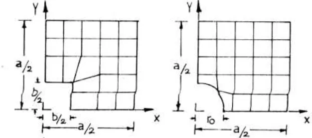
The results obtained by analysis of a simply supported square plate of different aspect ratios b/a and d/a respectively for plate with centrally located square and circular hole are presented in the form of graph and table of maximum deflection and maximum bending moment. Fig 1 shows the typical simply supported square plate (Quarter plate) with centrally located square and circular cut out with mesh. Fig. 2 shows the variation of maximum deflection with percentage opening for a plate with square and circular hole at centre. Fig.3 shows the variation of maximum moment Mx with percentage opening for a plate with square and circular hole at centre. Results of maximum deflection and maximum bending moments for different aspect ratio and percentage of opening are also tabulated in table 1. Contours of stress concentration factor for a S.S. Sq plate with square hole at centre of size 400mm x 400mm are presented in Fig. 4 and Fig. 5 shows the Contours of stress concentration factor for S.S. sq. plate with circular hole at centre of 400mm dia.
i) Comparison of Maximum Deflection:
Available Online at www.ijpret.com 19
ii) Comparison of Maximum Bending Moment:
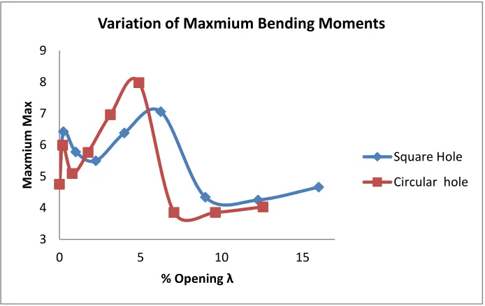
From the Fig. 3 and Table 1 it is observed that the maximum bending moments in the case of plate with central circular cutout/hole is less than the maximum bending moments for the plate with central square cutout/hole up-to 4% opening in the plate. Between 4% and 9% opening in the plate, the maximum bending moment in the former case is more than the later.
For the plate with central circular cutout/hole, the maximum bending moment is maximum at 4.908% opening and aspect ratio of 0.25. For the plate with central square cut out/hole, the maximum bending moment is maximum at 6.25% opening and aspect ratio of 0.25.
iii) Comparison of Stress Concentration Factors:
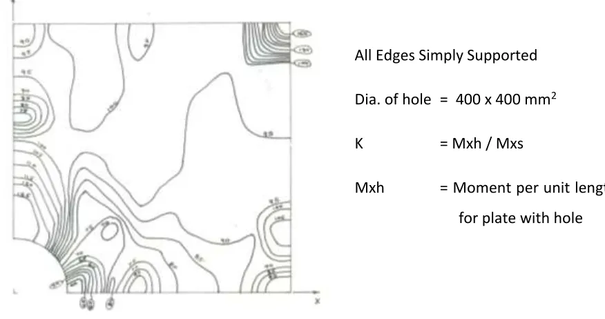
From the Fig. 4 and Fig. 5 it is observed that the concentration of stresses are more in case of square cutout/hole than the circular cutout/hole. Hence, the deflection and bending moment quantities are more in case of square cutout/hole than the circular cutout/hole. It is also observed that the stress concentration is more at re-entrant corner than at mid-point on the square holes in the plate. As the size of holes increase, the stress concentration at there entrant corner of square holes also increases. Stress concentration is also observed at corner of the plate with central square and circular hole. This is because of the lifting of edge of the plate.
Fig. 1 : Finite Element Model of S.S. Sq. Plate with cutout/hole (Quarter Plate)
All Edges Simply Supported
Plate size a = 2000mm
Thickness t = 10mm
Available Online at www.ijpret.com 20
Fig. 2 : Variation of maximum deflection with % opening for plate with cutout/hole at centre.
Fig. 3 : Variation of maximum moment Mx with % opening for plate with cutout/hole at centre. 3.9 4 4.1 4.2 4.3 4.4 4.5 4.6 4.7
0 5 10 15
M axm iu m Defl e ction
% Opening λ
Variation of Maximum Deflection
Suqare Hole
Circular hole
3 4 5 6 7 8 9
0 5 10 15
M axm iu m M ax
% Opening λ
Variation of Maxmium Bending Moments
Square Hole
Available Online at www.ijpret.com 21
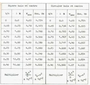
Table 1 : Maximum deflections and Moments for a simply supported square plate with central cutout/hole subjected to uniformly distributed load and variation of cutout/hole size.
(a=2000mm, t=10mm, qz=10KPa, E=2.1x10⁵N/mm2, = 0.3, = Varying)
Available Online at www.ijpret.com 22
Fig. 4 : Contours of Stress Concentration Factor 'K' for Square cutout/hole at centre of plate.
Fig. 5 : Contours of Stress Concentration Factor 'K' for Circular cutout/hole at centre of plate. All Edges Simply Supported
Hole Size = 400 x 400 mm2
K = Mxh / Mxs
Mxh = Moment per unit length
for plate with hole
Mxs = Moment per unit length
for solid plate
All Edges Simply Supported
Dia. of hole = 400 x 400 mm2
K = Mxh / Mxs
Mxh = Moment per unit length
for plate with hole
Mxs = Moment per unit length
Available Online at www.ijpret.com 23
CONCLUSION:
In this paper the results of maximum deflection and maximum bending moment for a transversely loaded simply supported square plate with centrally located square and circular cutout/hole of varying sizes are compared. Stress concentration factor is also observed by plotting contours of stress concentration factor. Finite Element with eight noded isoparametric plate element [Hinton's element (5)] is used to analyse the plate with cutout/hole. The results are presented in the form of graph and table and the values of maximum deflection and maximum bending moment for a S.S. Square plate with centrally located square and circular cutout/hole are compared. Contours of stress concentration factor are presented for sample case of plate with square and circular cutout/hole at centre. From this study it can be concluded that the maximum deflection and maximum bending moments in case of plate with square cutout/hole at centre is more than the circular cutout/hole at centre. The effect of size of cutout/hole (Percentage of opening and aspect ratio) also affects these quantities. As the percentage of opening / aspect ratio increases maximum deflection and maximum bending moment increase upto certain value and then decreases because load decreases as size of opening increase and becomes predominant than the decrease in stiffness of the plate due to cutout/hole. The stress concentration factors observed from the contours shows that the stress concentration is more for plate with square cutout than the circular cutout. It is also more at re-entrant corner and corner of the plate.
REFERENCE:
1. Deshmukh Pramod V. Analysis of Perforated Plates by Finite Element Method, M.E. Dissertation, Amravati University, 1990.
2. Seide P. and Chang P. H. H., Fintite element analysis of laminated plates and shells, NASA -C-157106, 1978.
3. Chaudhuri Reaz A. and Seide Paul, Triangular element for analysis of perforated plates under inplane and transverse loads, Computers and Structures, Vol. 24, No. 1, 1986, pp. 87-95.
4. EL-Hashimy M., Ausgewahlte Pllatenprobleme, Dissertaionnsdruckerei Leeman AG, Zurich, 1956.
5. Hinton E., Owen D. R. J., Finite Element Programming, Academic Press, 1977, London.
6. Earnest Zuber, Ein Beitrag Zur Berechnung Elastischer Platten mit Rechtech offnungen, Dissertation, Technischen Hochschule Darmstadt, December 1967.
Available Online at www.ijpret.com 24 8. Dieter Frenzel, Zweisetig Gestutzle, Quadratische Platten mit einer groberen offnung bei Beanspruchung durch eine gleichma ig Verteilte Plachenlast, Dr. Ing. Dissertation Technischen. Hochschule Carole - Wilhelmina, 1967.
9. Savin G. N., Stress distribution around holes, Naukova Dumka Press, Kiev, 1968.
10. Goodier J. N., The influence of circular and elliptical holes on the transverse flexure of Elastic plate, Phill. Mahazine, Vol. 22, No. 145, July, 1936.
11. Timoshenko S. P., Woinowsky - Krieger S., Theory of plates and shells, 2nd ed., McGraw - Hill, New York, 1959.
12. Bhawalkar S. M., Study of simply supported square plates for central hole and crack of varous shapes, M.E. Dissertation, Poona University, 1979.
13. Dupont C., Stress concentration around an open circular hole in a plate subjected to bending normal to the plane of the plate, Technical note No. 740, National Advisory Committee for Aeronautics, U.S.A., 1939.
14. Williams D. G. and Chapman J. C., Effect of shear deformation on uniformly loaded rectangular orthotropic plates, Institution of Civil Engineers, Paper 7236 S, 1969, pp 303-334. 15. Basu A. K. and Dawson J. M., Orthotropic sandwitch plates, Proc. of Institution of Civil Engineers, 1970, pp. 87-115.
16. Shah V. L., Plate with a hole, M.E. Dissertation, Poona University, 1973.
17. William Bradley, Deflections and moments in plates by Moire Fringe Method, Ph. D. Dissertation, University of Michigen, 1956.
18. Islam S. and Park R., Yield line analysis of Two way slabs with openings, Structural Engineer, London, June 1971.