ISSN: 1942-9703 CC BY-NC-ND
Abstract—This paper reported the design of a vehicle tracking
system using GPS technology and GSM/GPRS. With embedded
RTOS systems, the position of vehicles can be located in real
time. In this research, a microcontroller unit (MCU)
STM32F103RET6 with serial GSM modem and GPS receivers
integrated at a single module SIM908 is used. GSM modem
transmitted the vehicle’s position. GPS modem continuously
provided a vehicle’s position data and then stored it on web
servers. The position coordinate received by the user can be
viewed by using google map. The expected result is an applicable
VTS prototype on a vehicle with up to 2.5 meters of position
accuracy to fulfill the system specifications.
Index Terms—GPS-GSM/GPRS; Vehicle Tracking System;
Microcontroller; SIM908
I.
INTRODUCTION
RIVATE
vehicles and public safety is a major concern
today.
In this era of technology, besides road user
regulations, various specific information systems can be
apllied to ensure driving security such as Vehicle Tracking
System (VTS).
VTS is
a system containing electronic device installed in a
vehicle to enable the user to track the vehicle's location.
VTS
consists of locating device such as GPS and signalling device
such as GSM/GPRS module. Most VTS was made with
separated GPS module and GSM/GPRS module so that it is
relatively difficult to switch between them. Also, it requires
more space.
A SIM908 module is the solution for this because both
modules are integrated as one. So, it also saves spaces in the
design. GSM/GPRS is chosen to connect the GPS device to
the web server because it is relatively cheap. Besides, it has
extensive coverage area which is almost the entire territory of
Manuscript received January 11, 2017. This research activity was conducted as part of the research project “Development of Microwave to Light Wave Converter using Antenna and Optical Modulator for Telecommunication and Measurement Applications” through The Excellent Research Grant from Indonesian Institute of Sciences (LIPI), Indonesia. Also authors would like to thank to Langlangbuana University Bandung for data support during research process.
P. Daud , D. Mahmudin, Y. N. Wijayanto, and P. Putranto are with the Research Center for Telecommunications and Electronics, Indonesian Institute of Sciences, Bandung, Indonesia (phone: 2504661; fax: 62-22-2504659; e-mail:pmkdaud@ gmail.com).
J.A. Simalongo is with Departement of Electrical Engineering, Langlang Buana University, Bandung, Indonesia.
Indonesia [1].
To manage the system, a proper microcontroller is required.
STM32F103RET6 is chosen because the specification (will be
presented at section II.E) meet the requirements of the system.
It also has a length of 32-bit registers, which means it stores
32 bits of data in one of its assembly instructions. These
instructions will be needed in the industrial application which
require high precision and large data capacity. On the software
part, free
Real Time Operating System (
RTOS) is used as
embedded systems to ease the programming and real time
tracking can be conducted [2].
In this paper, we propose a technique for real-time vehicle
tracking using microcontroller with integrated module of GPS
and GSM/GPRS. The position of vehicle is identified by the
GPS through satellites. The information is transferred to the
monitoring station via GSM/GPRS. The GPS and GSM/GPRS
are operated by microcontroller. Therefore, the position of the
vehicle can be monitored using the proposed technique.
Additionally, the vehicle movement can be also tracked using
the proposed techniques by taking the position data and
sending it to the monitoring station. Therefore, real-time
vehicle tracking can be conducted.
II.
SYSTEM COMPONENTS
A.
Basic Principle
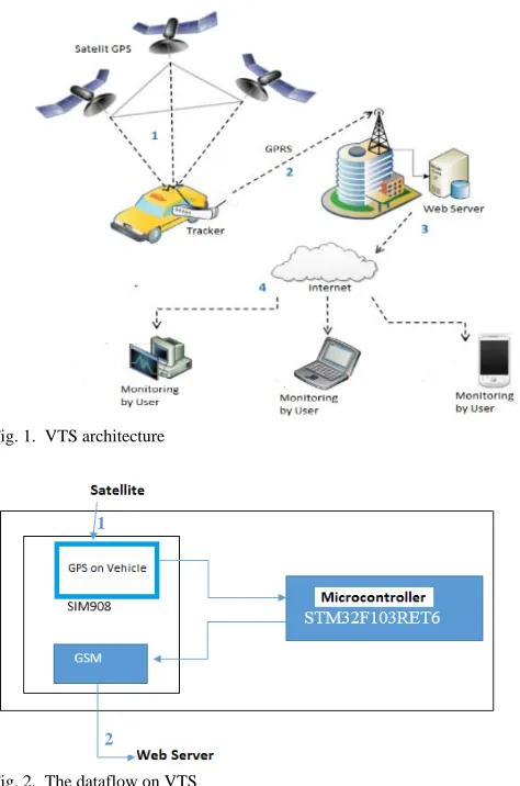
Fig. 1 shows the VTS architecture. The basic principle of
VTS is started from no.1 when the GPS antenna on the car
sends the signal to the GPS satellites and then receives each
signal back from the satellites to be proceeded to give the
exact coordinate of the car position. Later, the position data is
sent to the server via GPRS channel (no.2). The server saves
all the data from other vehicles. This provides other
information such as traffic density in a certain location. Next,
those data are uploaded to the internet (no.3) so that it will be
accessible to all users with any kind of device (no.4).
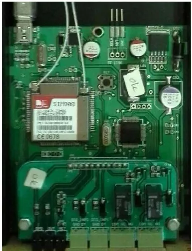
Fig. 2 shows two processes occurring on the
microcontroller device. First is the position sensing process by
GPS on vehicle under the coordination with satellites, and
second is the communication process by the GSM modem
which is used for sending the data to a web server using
HTTP protocol.
B.
GPS Receiver
The GPS receiver is a tool receiving GPS signal for
Design of Vehicle Tracking System using MCU
STM32F103RET6 and SIM908
P. Daud, J. A. Simalongo, D. Mahmudin, Y. N. Wijayanto, and P. Putranto
determining the actual location of it on earth. It provides
longitude and latitude information, and some modified ones
also calculates altitude. This device is used in the military,
aviation, shipping and consumer product applications. A GPS
receiver consists of an antenna, processor and accurate clock.
A display may be added to provide location and speed
information to the user. A receiver is often described by its
number of channels which tells the number of satellites can be
monitored simultaneously. The GPS receiver is equipped with
an input for differential corrections, using the RTCM SC- 104
format. Many GPS receivers can convey the position data to a
PC (personal computer) or other devices which uses the
NMEA 0183 protocol.
C.
GPS Modem
A GSM Modem is a type of modem that uses a SIM card,
and operates on a subscription to a mobile phone service
providers. This hardware looks like a cell phone. Wireless
modem operates like a dial-up modem. The main difference
from both is that the dial-up modem is sending and receiving
data via wireline or fixed wireless model while wireless
modem is
Fig. 1. VTS architecture
Fig. 2. The dataflow on VTS
sending and receiving data over a radio wave. Like the mobile
phone, GSM modem requires a SIM card to operate. Both
standard AT commands. The GPS antenna specifications
needed for this research is shown in Table I.
D.
AT Commands
AT means ATtentions. AT commands give instructions to
mobile devices and public wired telephone. Commands sent
to the phone, which can be either a GSM modem or a PC
modem. Different manufacturers may have a different number
of AT commands.
E.
MCU STM32F103RET6
STM32F103RET6 is a type of 32-bit microcontroller
architecture developed by STMicroelectronics [4]. This
microcontroller included in the family of Cortex - M series. Its
specifications can be seen in Table II. The processor in this
series has been developed specifically for microcontroller,
where the demand for speed, process time determination, and
interrupt setting along with the minimum number of gate
silicon (minimum silicon area determines the final price of the
processor) and minimum consumption power are what
consumers favor of.
F.
SIM908 Module
The SIM908 module is a complete Quad-Band
GSM/GPRS module that combines GPS technology for
satellite navigation [5]. This module specifications is shown in
Table III. A design which combines GPS and GPRS in one
package will significantly save customer’s cost and time to
develop
GPS-TABLEI
GPSANTENNA SPECIFICATIONS [3]
Feature Explanation
Center Frequency 1575.42MHz ± 3MHz V.S.W.R 1.5:1 Bandwidth ± 5 MHz
Impedance 50 ohm
Peak Gain > 3dBic Gain Coverage > -4dBic
Polarization Right Hand Circular Polarization (RHCP)
TABLEII
STM32F103RET6SPECIFICATIONS [4]
Peripheral Specification
Flash Memory 512 kb
GPIOs 51 CPU Frequency 72 MHz
Operation Voltage 2.0 – 3.6 V 1
ISSN: 1942-9703 CC BY-NC-ND
based application. Having an advance in interface and
industrial GPS standards, this module allows any changing
positioned vehicle to be tracked at any location and any time
as long as the signal exists.
G.
FreeRTOS
A Real Time Operating System (RTOS) is an operating
system required to enable the system takes performance
instantaneously whenever it is needed to do so. One of the
advantages of an RTOS is its ability to perform consistently in
duration it needs as well as in the task of applications that it
does [7]. RTOS has an algorithm for scheduling process
which flexibility to organize the process and doing priority
process in a computer system. FreeRTOS (Free Real Time
Operating System) is an open source real time operating
system for embedded devices such as microcontrollers [8].
III.
HARDWARE ASSEMBLY
Overall vehicle tracking system hardware architecture is
shown in Fig. 3.
After development and assembly process, the
desired device will be obtained as shown in Fig. 4.
Fig. 3. Hardware architecture design
Fig. 4 Implementation of the hardware design
IV.
SOFTWARE DEVELOPMENT
The software is built using the C programming language
and IDE CooCox as a platform [9]. The software development
process is divided into 3 main tasks and 2 supporting tasks.
The main task consists of three stages, namely:
1.
GSM
Task : to configure and activate the existing
facilities on the GSM modem.
2.
GPS
Task : to take GPS data and to parse the
determined variables.
3.
HTTP Task : to compile information before transmission
via HTTP socket.
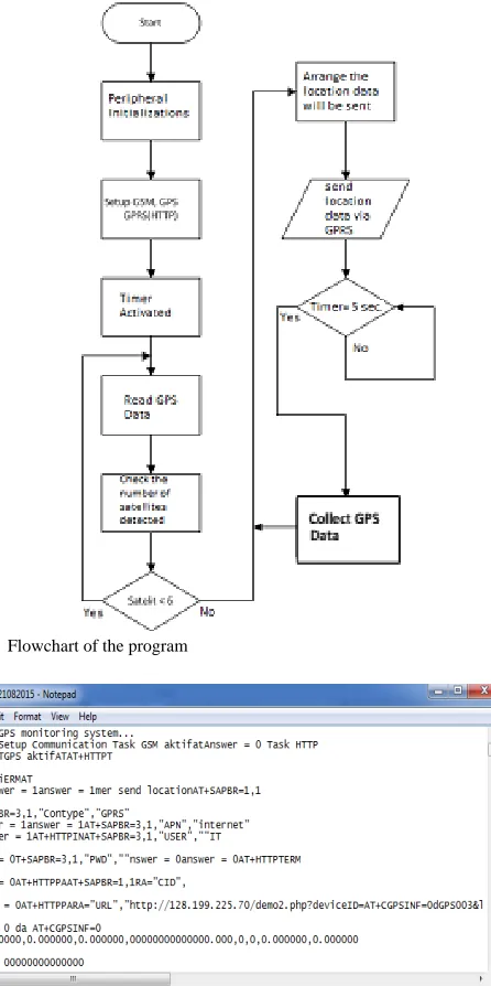
The flowchart in Fig. 5 shows how the software system in this
research worked.
V.
FIELD TESTING
A.
VTS Device Performance Testing
For system testing, we used Hercules software [10]. This
application is able to see the VTS process. The important data
are displayed by this application, including date, longitude,
latitude, altitude.
Fig. 6 showed that the device has been successfully
performed all 3 tasks. This is called the setup mode. Next, the
device will enter the running mode, which is the process of
finding a minimum of 6 satellites to determine the location of
the vehicle. Once the location is obtained, then the VTS will
send them to the web server to be processed and displayed to
the user.
TABLEIII SIM908SPECIFICATIONS [6]
Feature Explanation
Specification 850/900/1800/1900 MHz, GPRS ulti-slot class 10, GPRS mobile station class B, Compliant to GSM phase 2/2+, Control via AT commands, SIM application toolkit, Supply voltage range: GPRS 3.2-4.8/GPS 3.0-4.5 V, Low power consumption, Transfer Data GPRS class 8/10: max 85.6 kbps(downlink) GPS Receiver type: 42 channel, GPS L1 C/A code, High
Fig. 5 Flowchart of the program
Fig. 6. Result of device testing
B.
Position Vehicle Tracking
Vehicle position data collection is performed by installing a
VTS device in a vehicle and then selected the route to be
travelled by vehicles. The device
received a power from the
car. Shortly after the car is turned on, the device will be active
and start the process. From the user perspective, vehicle
tracking can be done either through a media laptop, desktop,
tablet, or mobile phones which have GSM and GPRS
connection and web browser applications on the gadget. Users
are able to access the server by entering a certain IP address
on the web browser so users can see the vehicle position data.
Table IV shows the movement of the vehicle during a
certain time by observing the latitude and the longitude of the
vehicle. Furthermore, the vehicles position on a map can be
seen on Fig. 7.
Fig. 7 The position of the vehicles on a map
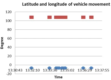
Vehicle position data (Table IV & Fig. 7) is plotted on a
graph shown in Fig. 8 so that the shift of its movement is
observable for further analysis.
From the observation result
graph, it can be seen that at certain intervals, there are greater
distance between a marker to the next one. It can be caused by
two factors: first, VTS device failed to receive the vehicle’s
coordinate from the satellites, and / or second, VTS device
failed to send the vehicle’s coordinate from the satellites to the
web server.
TABLEIV VEHICLE’S POSITION
Time latitude longitude
13:32:02 -6.89089864 107.61098704
13:32:07 -6.89089864 107.61098704
13:33:32 -6.89089864 107.61098704
13:33:37 -6.89089864 107.61098704
13:34:05 -6.89089864 107.61098704
13:34:10 -6.89089864 107.61098704
13:34:15 -6.89089864 107.61098704
13:34:20 -6.89089864 107.61098704
13:34:25 -6.89089864 107.61098704
13:34:35 -6.89091880 107.61096860
13:34:40 -6.89090704 107.61096548
13:34:45 -6.89089528 107.61096464
13:34:50 -6.89089544 107.61094840
13:34:55 -6.89089656 107.61084396
13:36:20 -6.89259936 107.61045004
13:36:25 -6.89276184 107.61044824
13:37:00 -6.89325368 107.61034560
ISSN: 1942-9703 CC BY-NC-ND
Fig. 8. A graph of the observed vehicle’s position.
The first factor can occur if the GPS receiver was unable to
capture the satellite signals due to obstructions between the
GPS antenna and GPS satellites. While the second one may
occur because of GSM signal interference or slow internet
connection (GPRS) at that moment so the data did not arrive
at the destination (web server).
VI.
CONCLUSION
The main function of this system is to track the vehicle
position in real time by utilizing the free RTOS embedded
system, GPS technology and GSM/GPRS. This system can
run
properly. The tracking history feature can also display all
the travel history of the desired period. However, the VTS
tracking performance is still not perfect because there were
more than 10 seconds of delay during deliveries. Delay can be
caused by slow Internet connection (GPRS) at that moment.
VTS performance in transmitting the position is good
enough bacause it is capable of transmitting the data in 5
seconds interval. This is particularly useful in tracking the
vehicle in a narrow area because the displacement of the
vehicle will appear so smooth. However, in a large area, it is
required to provide a large data storage in order to save the
amount of data received by the VTS.
The VTS performance is strongly influenced by the internet
connection to the web server. A better internet connection
leads to a better vehicle tracking process. This is due to the
demand of following the vehicle marker on Google Maps
needs a large bandwidth, especially with zoom feature on
Google Map,and this goes in continuous time as long as the
desired tracking process.
ACKNOWLEDGMENT
This research activity was conducted as part of the research
project “Development of Microwave to Light Wave Converter
using Antenna and Optical Modulator for Telecommunication
and Measurement Applications” through The Excellent
Research Grant from Indonesian Institute of Sciences (LIPI),
Indonesia. Also authors would like to thank to Langlangbuana
University Bandung for data support during research process.
REFERENCES
[1] Bhatia J.S. and Verma Pankaj. Design and Development of GPS-GSM Based Tracking System with Google Map Based Monitoring. IJCSEA, Vol.3. No.3, 2013
[2] Labrose, J. Jean. µC/OS-II: The Real Time Kernel. CA: R&D Books. ISBN0- 87930- 543- 6, 1999.
[3] Datasheet GPS Active Antenna Specification. Available. http://www.picaxe.com/docs/GPS010_antenna.pdf
[4] Rika Sustika, Joko Suryana. Nonlinear Filtering with IMM Algorithm for Coastal Radar Target Tracking System.TELKOMNIKA Journal of Electrical Engineering. 2015;13 (1) : 211-21
[5] P. Daud, N. Armi, D. Mahmudin, D. Syamsi, and Y.N. Wijayanto, "Concept Development of Integrated Monitoring System Model to Support Activities Monitoring in the Border Region," 2015 International Conference on Smart Sensors and Application, Kuala Lumpur, May 2015.
[6] Kurniawan D, Adhi P, Satyawan AS, Syamsu I, Praludi T. Object Detector on Coastal Surveillance Radar Using Two-Dimensional Order-Statistic Constant-False Alarm Rate Algoritm. TELKOMNIKA Indonesian Journal of Electrical Engineering. 2015; 13.(2): 624-631 [7] Melot, Nicolas. Study of an Operating System: FreeRTOS,
www.freertos.org on February 2015.
[8] Wilson, Ron. 2011 Embedded Market Study, https://web.archive.org/web/20120402223224/http://www.eetimes.com/e lectrical-engineers/education-training/webinars/4214387/2011-Embedded-Market-Study on April 2011.
[9] Kernighan, Brian W. and M. Ritchie. The C Programming Language, 2nd edition. Englewood Cliffs, New Jersey: Prenctice Hall. ISBN 0- 13- 110362- 8, 1988.
[10] http://www.gpstrackingtracker.com/GPS/Hercules on December 2016.
P. Daud is Senior researcher and the leader of Microwave, Radio Frequency and Photonic Research Group at the Research Center for Telecommunications and Electronics, Indonesian Institute of Sciences (PPET-LIPI), Bandung, Indonesia. He is also lecturer in Langlang Buana University. His current research involves establishing a bridge between the fields of photonics and microwave devices. Specially, he focuses on the development of microwave and photonic-optic devices for radio over fiber (RoF) system in telecommunication applications.
J. A. Simalongo graduated from electrical engineering in Langlang Buana University. His interests involves control engineering, radio frequency, and information system
D. Mahmudin is Junior Investigator at the Research Center for
Telecommunications and Electronics, Indonesian Institute of Sciences (PPET-LIPI), Bandung, Indonesia. His current research involves establishing a bridge between the fields of photonics devices. Especially, he focuses on the development of Photonic Integrated Circuit for sensor and telecommunication applications.
Y. N. Wijayanto joined the Research Center for Telecommunications and Electronics, Indonesian Institute of Sciences (LIPI) Indonesia since 2005. He received Ph.D. degrees in electrical engineering from Osaka University Japan in 2013. He has experiences to work on high-speed electro-optic modulators, wireless radio to optical signals converters, and fiber- wireless technology. Now, he is concern to study and research on combination of radio and optical technology for communication, sensing, and imaging applications. Dr. Wijayanto is a member of IEEE Photonics and InOS. He was the recipient of the LIPI Exemplary Researcher in 2017, the LIPI Inventor Award in 2015, the JSAP Young Scientist Oral Presentation Award in the 60st JSAP Spring Meeting in 2013, and the IEEE Photonics Society Japan Young Scientist Award in 7th APMP 2012.