300
Enhanced propagation model for wireless network using COST 231
Girjesh Kumar Suryawanshi, Prof. Narendra Sharma
Computer Science & Engineering Department, SSSIST, India
Abstract:- Implementations of wireless network wave propagation models are necessary to determine propagation characteristic through a medium. Propagation study provides an estimation of signal characteristics. This paper evaluates about propagation models, their path loss behavior, propagation mechanisms, and propagation prediction techniques. A propagation model is a set of mathematical expressions, diagrams, and algorithms used to represent the radio characteristics of a given environment. The accuracy of any particular propagation model in any given condition will depend on the suitability among the constraints required by the model and depend on terrain. This paper proposes new semi deterministic model derived by walficsh and Ikagami, this model simulation results represents the accuracy in terms of through put, end to end delay, average jitter and total packet received with respect to cost 231 Hata model and cost 231 (W.I) models and also shows some limitations, proposed model is unable to calculate multiple reflection loss caused by multi-screen.
Keywords:- Propagation mechanism, propagation models, Propagation prediction techniques.
1.INTRODUCTION
Business accomplishment of remote, since its underlying usage has chap to an enthusiasm between remote designers in understanding and anticipating radio proliferation trademark in distinctive urban and rural region, far reaching development of remote system, it is valuable to have the ability of deciding way misfortune. The advancement of effective transmission, operation and administration innovations and a dynamic decrease in the size of the cells requires a more prominent suitability on the estimations of the framework scope, which is given by spread misfortunes, all together to get "complete scope" with which the administrator endeavors to affirmation the nature of administration. Hence an exact and adaptable expectation approach of scope with simple execution is required [1]. It is elusive a procedure of sign expectation which accomplishes the accuracy complexity time worldview. The point
of finding a solitary technique for any metropolitan environment is inadequate in light of the fact that it is clear that the execution of a framework is firmly identified with the operation locale. The principle point of this paper to locate the precise proliferation model for the radio channel lessening for metropolitan range, Wave engendering models are important to decide proliferation attributes for any arbitrary component. A comprehension of radio engendering [2] is crucial for thinking of suitable configuration, arrangement, also, administration systems for any remote system. In the following is a brief review of spread component, segment 3 Examine principle spread model, segment 4 is portraying propose work, segment 5 is Computer Simulation and utilized strategy and segment 6 is results examination and last area is conclusion.
2.PROPAGATION MECHANISM
301
is relative to 1/ (d1+d2). For single diffraction, the field is relative to (d1/d2 (d1+d2)) - 0.5. For different diffraction and for a source enlightening all edges, the field is relative to 1/d1.9. For volume dissipating and harsh surface disseminating, the field is relative to 1/ (d1.d2). For entrance and ingestion, the field is mostly weakened by a consistent. For the wave managing wonders, the logarithm of the field is related to d.
Fig.1. Propagation phenomena
3.PROPAGATION MODELS
Spread models [7] in remote correspondence have centered on anticipating the normal got signal quality at a given separation from the transmitter and in addition the irregularity of the signal quality in close vicinity to a specific area. Engendering models that anticipate the mean sign quality for an irregular transmitter – recipient partition separation are valuable in assessing the radio Coverage region of transmitter and are called substantial scale spread models. The engendering models are for the most part used to separate the nature of portable correspondence.
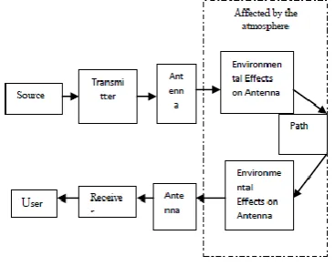
Fig. 2 Block diagram for propagation loss calculations
An engendering model is an arrangement of numerical expressions, graphs, and calculations used to speak to the radio qualities of a given domain. Proliferation model are three sorts observational model, semi deterministic model, deterministic model Empirical models depend on estimation information, straightforward, use factual properties,
What's more, not extremely exact Semi-deterministic models depend on experimental models and deterministic viewpoints. Deterministic models are site-particular; require colossal number of geometry data refer to, imperative computational exertion, exact. In Figure 2 we are demonstrating fundamental strides of way misfortune count [9]. Figure show what are the essential element for ascertaining way misfortune in remote system.
3.1 Free Space Model
This is a vast scale model. The got force is as it was reliant on the transmitted force, the reception apparatus' additions and on the separation between the sender and the recipient. It accounts principally for the way that a radio wave which moves far from the sender needs to cover a bigger region. So the got power diminishes with the square of the separation. The free space spread model expect the perfect engendering condition that there is stand out clear observable pathway way between the transmitter what's more, recipient. H. T. Friis exhibited the accompanying comparison to compute the got signal force in free space at separation d from the transmitter [8] [16].
Where PT is the transmitted sign force GT and GR are the receiving wire increases of the transmitter and the recipient individually is the wavelength. It is normal to choose GT = GR =1.then,
( ) ( )
Expressed in dB as:
( ) =
=
Then,
One can see from the above free space mathematical statements that 6 dB of misfortune is connected with a multiplying of the recurrence. This same relationship additionally holds for the separation, if the separation is multiplied, 6 dB of extra misfortune will be experienced.
3.2 Two Ray Ground Model
302
beneficiary. In any case, as a general rule the sign achieves the beneficiary through numerous ways (on account of reflection, refraction and scrambling). The two-way show tries to catch this marvel. The model expects that the sign achieves the beneficiary through two ways, one a viewable pathway way, and the other the way through which the reflected wave is gotten. As per the two-way model, the got force is given by [10],
Where Pt is the transmitted force, Gt and Gr is the transmitter what's more, collector reception apparatus picks up, individually, in the heading from the transmitter and collector, d is the separation between the transmitter and collector, and ht and hr are the statures of the transmitter and collector, separately.
3.3 Okumura Model
This segment examines diverse spread procedures Okumara is the primary system to discover way misfortune in urban range. Okumura's model [11] [15] is most broadly utilized for sign forecasts in urban and rural zones working in the scope of Source Transmitter Antenna Affected by the climate Environmental Effects on Antenna Path Environmental Effects on Antenna User Receiver Antenna 150MHz to 1.92 GHz. The premise of the technique is that the free space way misfortune between the transmitter and beneficiary is added to the estimation of Amu(f,d),where Amu is the middle lessening, in respect to free space in a urban territory with a base station compelling radio wire stature Hte 200 meter and portable station tallness Hre is 3 meter To decide way misfortune utilizing Okumura's model, the free space way misfortune between the purposes of hobby is first decided, and after that the estimation of Amu (f, d) is added to it along with redress elements to represent the kind of territory as communicated in.
L50 (dB) = Lf +Amu –AHte–GGhre- Garea
Here, L50(dB) is the 50 percentile estimation of proliferation way misfortune, LF is proliferation loss of free space, Amu is the middle weakening with respect to free space, GHte , GHre , Garea are BTS reception apparatus stature pick up component, versatile receiving wire tallness pick up element also, increase because of the kind of environment. Okumara model is exact in nature implies that all parameters are utilized to particular range dictated by the deliberate information. On the off chance that
the client finds that one alternately more parameters are outside the extent then there is no substitute.
3.4 Hata Propagation Model
The Hata model is an observational detailing [12] of the graphically misfortune information gave by Okumura's model. The equation for the middle way misfortune in urban zones is given by
Where fc is the recurrence (in MHz), which fluctuates from 150 MHz to 1500MHz hte and hre are the successful statures of the base station and the portable radio wires (in meters), separately. D is the separation from the base station to the portable radio wire; a (hre) is the rectification component for the powerful receiving wire tallness of the portable unit, which is a component of the span of the region of scope. For little to medium-sized urban communities, the portable receiving wire redress variable is given by:
a (hre = (1.1logfc -0.7) hre–(1.56logfc-0.8) dB. Path loss in suburban area
– 5.4
The path loss in open rural area as is expressed
These comparison enhanced execution estimation of okumara model, this strategy is great in urban and rural region however in country zones execution degreases on the grounds that country territory forecast is rely on upon urban territory . This model is very appropriate for extensive cell versatile frameworks, yet not for individual correspondences frameworks that cover a round region of roughly 1 km in radius.
3.5 Walfisch and Bertoni model
303
P1 expression is in view of diffraction and decides the sign misfortune from the housetop to the road. The model has been embraced for the IMT- 2000 standard.
3.6 Cost 231(Walfisch and Ikegami) Model This experimental model is a mix of the models from J. Walfisch and F. Ikegami. It was produced by the COST 231 venture. It is presently called Empirical COST-Walfisch-Ikegami Model. The recurrence ranges from 800MHz to 2000 MHz This model is utilized fundamentally as a part of Europe for the GSM1900 framework [14] [15]. Path loss L5O(dB)=Lf +Lrst +Lmsd
Where
Lf = free-space loss
Lrts= rooftop-to-street diffraction and scatter loss Lmsd= multi-screen loss
Free space loss is given as
The rooftop-to-street diffraction and scatter loss is given as [14]
(
)
With
{
(
)
(
)
Where
With w = width of the roads Where Lori = Orientation Loss
φ= incident angle relative to the street
The multi-screen loss is given as:
(
)
where
{
{
This model is confined to the accompanying scope of parameter: recurrence scope of this model is 800 to 2000 MHz and the base station stature is 4 to 50 m and versatile station tallness is 1 to 3 m, what's more, separation between base station and versatile station d is 0.02 to 5km.
4.PROPOSED WORK
This paper proposed new cost 231 (walfisch and Ikagami) model. Fetched 231 wi model has impediments, this model ascertain just housetop to-road diffraction and disperse misfortune and multi-screen diffraction misfortune. It can't figure misfortune because of various reflections. In expanded cost wi model we include the new term Lsv which is utilized to figure numerous reflections inside building piece. The model gives an engendering misfortune capacity L with the taking after parameters: recurrence f base station tallness hbase, MS tallness hm separation between the MS and the BS d, road width w, point between the road and spread heading φ, building stature hroof , building partition b, and territory tallness. New model is: L5O(dB)=Lf +Lrst +Lmsd +Lsv
Where :- Path loss in Line of Sight condition frequency MHz > 0
path loss dB = 42.6 + 26.0 ×log10(distance Km)+ 20.0 × log10(frequency MHz)
304
free space misfortune L0, different screen diffraction misfortune Lmsd, and rooftop top-to street diffraction and scrambles misfortune Lrts and sign variety misfortune Lsv. freeSpaceLoss = 32.4 + 20.0 × log10(distanceKm) + 20.0 × log10 (frequencyMhz) Roof-top-to-street diffraction and scatters loss: Lrts= - 16.9 - 10.0 × log10 (val1) + 10.0 × log10(frequencyMhz) + 20.0 × log10(val2) + lori and multi-screen loss Lmsd. Lmsd=Lbsh + ka + kd × log10(distanceKm) +kf × log10(frequencyMhz)- 9.0 × log10(b)
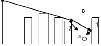
Fig.3. Two rays at the MS considered by models
New Model considers two fundamental beams landing to the versatile as appeared in Figure 3. The first is the beam that, is diffracted by the slightest building (1) and arrives specifically to the versatile. The second beam is diffracted by building (1) and reflected in the building (2).This is new augmented cost 321 wi model. The term Lf and Lrts are same as old model. In Lmsd We change the quality of kd. Lsv = - 11.32 + 3.3 × (log(dsv1/m) + 3.3 × log(dsv2/m))
Fig. 4 be considered in the case of finite screens reaching the MS coming from the corners New model include a misfortune term Lsv with a logarithmic reliance with the separations from every road crossing point, dsv1 and dsv2 has observationally been balanced in view of field estimations. Extra beams ought to be accounted as fundamental beams as they take after the paradigm of diffraction or a diffraction–reflection. Extra beams endure a diffraction on the edges set at the corners and diffraction-reflection which happens in the intersection of the roads.
5. SIMULATION & MODELING
In this paper all the recreation work is performed in NS-2 [17] remote system test system form 2.0. At first number of hubs are 10, Simulation time was taken 200 seconds and seed as 1. Every one of the situations has been composed in 500m x 500m territory. Versatility model utilized is Random Way Point (RWP). In this model a versatile hub is at first set in an irregular area in the reproduction territory, and after that moved in a haphazardly picked heading between at a steady speed. The development continues for a particular measure of time or separate, and the procedure is rehashed a foreordained number of times. Hub in system moves with consistent velocity of 10 m/s and with interruption time of 0sto 50s. All the reenactment work was done utilizing cost 231 Hata model, cost 231 wi and its variation with AODV steering convention .Network movement is given by utilizing consistent Bit Rate (CBR) application.
Table 1: Simulation Methodology
Throughput is the measure of the number of packets successfully transmitted to their final destination per unit time. It is the ratio between the numbers of sent packets vs. received packets. Average End to End Delay signifies the average time taken by packets to reach one end to another end (Source to Destination). Average Jitter Effect signifies the Packets from the source will reach the destination with different delays. A packet's delay varies with its position in the queues of the routers along the path between source and destination and this position can vary unpredictably. Total Bytes received are the measure of total packet received by server. The packets may be drop due to heavy traffic. So received packets may be vary according to traffic conditions.
6.RESULTS AND ANALYSIS
305
Normal Jitter Effect means the Packets from the source will come to the destination with various postponements.
Fig: 5
Fig: 6
Fig: 7
Fig: 8
Fig: 9
Fig: 10
Fig: 11
Fig: 12
306
system. It must be seen that collector can get most extreme byte at new cost wi, however it is some of the time less because of blockage in system.
7.CONCLUSION
This paper talks about cost 231 Hata model and Cost 231 walficsh Ikagami model, yet both models are not effective and exact in urban environment, there are a few impediments in these model, such that different reflection because of various screen in urban environment. Proposed model evacuates these impediments and enhance throughput in contrast with the cost 231 hata and expense 231 walficsh Ikagami, all recreation work is done in NS-2. This paper contrast new cost 231 wi model and regard to cost 231 hata and cost 231 walficsh Ikagami model, execution measurements utilized for this work is Throughput, Average End to End Delay, Average Jitter, Total Bytes got. Through put of new model is unrivaled when expanding number of hub as well as expanding interruption time, yet normal jitter and normal end to end postponement is high. New cost231 wi model move forward execution and precision. The fundamental point of this exploration is to discover a spread model for the radio diverts lessening in the recurrence range 1800 MHz in urban environment. This model has been created for urban regions of little full scale cells.
8. REFERENCES
[1]. Casaravilla J., Dutra G., Pignataro N. &Acuna J. “Propagation Model for Small Macro cells in Urban Areas” IEEE transactions on vehicular technology, vol.58, no. 7, September 2009. [2]. H. L. Bertoni, “Radio Propagation for Modern
Wireless Systems” Upper Saddle River, NJ, Prentice Hall PTR,2000, pp. 90-92.
[3]. Thomas Kurner and Dieter J. Cichon “Propagation Prediction Models”.
[4]. Mark r. alexander “understanding and predicting urban propagation losses” naval postgraduate school Monterey, California September 2009. [5]. H. Sizun, P.de Fornel, “Radio Wave Propagation
for Telecommunication Applications” Springer,
ISBN: 978-3540407584, 2004.
[6]. F. D. Cardoso, S. Taccori, L. M. Correia, IST-2001-32125 FLOWS, “Initial Propagation Models”, 2002.
[7]. Nagendrasah and Amit Kumar “CSP Algorithm in Predicting and Optimizing the Path Loss of Wireless Empirical Propagation Models ”International Journal of Computer and Electrical Engineering, Vol. 1, No. 4,October, 2009.
[8]. James Demetriou and Rebecca MacKenzie “Propagation Basics” September 30, 1998.
[9]. Robert K. Crane “Propagation Handbook for Wireless Communication System Design”.
[10]. Ayyaswamy Kathirvel, and Rengaramanujam Srinivasan “Analysis of Propagation Model using Mobile Ad Hoc Network Routing Protocols” International Journal of Research and Reviews in Computer Science (IJRRCS),Vol. 1, No. 1.
[11]. Sagar Patel, VedVyas Dwivedi and Y.P. Kosta “A Parametric Characterization and Comparative Study of Okumura and Hata Propagation-loss prediction Models for Wireless Environment” Number 4 (2010).
[12]. Tapan K. Sarkar, ZhongJi, Kyungjung Kim, Abdellatif Medour “A Survey of Various Propagation Models for Mobile Communication” IEEE Antennas and Propagation Magazine, Vol. 45, No. 3, June 2003.
[13]. Theodore S. Rappaport, 2002, Wireless Communications: Principles and Practice, Prentice Hall PTR.
[14]. R. Mardeni and K. F. Kwan “optimization of hata propagation prediction model in suburban area in Malaysia” Progress In Electromagnetics Research C, Vol. 13, 106, 2010.
[15]. J. d. parsons “The mobile radio propagation channel” second edition, Jon welly and sons Ltd. [16]. Ibrahim Khider Eltahir “The Impact of Different
Radio Propagation Models for Mobile Ad hoc Networks (MANET) in Urban Area Environment” The 2ndInternational Conference on Wireless Broadband and Ultra Wideband Communications, 2007.