*
Corresponding author: Tel: +98-9125390411Design and Kinematic Analysis of a 4-DOF
Serial-Parallel Manipulator for a Driving
Simulator
Amir Jaberi
a, Ali Nahvi
a,*, Milad Hasanvand
a, Mehdi Tale-Masouleh
b, Mohammadreza Arbabtafti
c,
Mojtaba Yazdani
aa
Virtual Reality Laboratory, K.N. Toosi University of Technology, Tehran, Iran, E-mail: a.jaberi@ut.ac.ir
bHuman-Robot Interaction Laboratory, Faculty of New Sciences and Technologies, University of Tehran, Tehran, Iran, E-mail:
m.t.masouleh@ut.ac.ir.
c
Shahid Rajaee Teacher Training University, Tehran, Iran.
A R T I C L E I N F O A B S T R A C T
Article history:
Received: August 12, 2014. Received in revised form: November 24, 2014.
Accepted: November 29, 2014.
This paper presents the kinematic analysis and the development of a 4-degree-of-freedom serial-parallel mechanism for large commercial vehicle driving simulators. The degrees of freedom are selected according to the target maneuvers and the structure of human motion perception organs. Several kinematic properties of parallel part of the mechanism under study are investigated, including the inverse and the forward kinematics problems, workspace determination, singularity, and kinematic sensitivity analysis. The workspace of the parallel part of the mechanism is obtained by interval analysis. Moreover, using elimination theory, a univariate expression representing the forward kinematics solution of the parallel part is obtained.
Keywords:
Driving simulator Parallel mechanisms (PM) Forward kinematics problem (FKP) Kinematic sensitivity
Interval analysis
1. Introduction
Early simulators were used extensively in the aviation industry for aircrew training [1]. The development and advent of industrial Parallel Mechanisms (PMs) gained popularity in other fields such as ground vehicle driving simulators and CNC machines. In [2], a comprehensive report is presented on the development history of simulators from 1948 to 2007. In 1994 and 2003, Ford and BMW, two major car companies, developed two six-degree-of-freedom (DOF) driving simulators. These simulators generate their motion by their hydraulically-actuated hexapod mechanisms [3, 4]. In the academic side, the National Advanced Driving Simulator (NADS) at the university of Iowa developed a few driving simulators becoming the state of the art for other car companies due to their great success [5]. For example, the Toyota Driving Simulator [6] is inspired by NADS products. In 2004, TUTOR, a truck driving simulator was developed at INTA (Spain) [7]. Selecting the best possible set of DOFs for a driving simulator is of paramount importance. In this paper, from the study
conducted on the conceptual design, the opted DOFs are
surge, pitch, roll, and heave. The next step is to specify
the mechanism architecture to provide the desired motion. To exploit the advantages of both serial and parallel mechanisms, we decided to have the final mechanism as a hybrid one, i.e., a serial-parallel manipulator. A 2-PSS+1U PM is mounted on a surge platform. P, S, and U denote prismatic, spherical, and universal joints, and the underlined P indicates the actuating joint. The parallel part of the mechanism produces two rotational DOFs (pitch and roll). The heave motion is generated by a pneumatic actuator attached under the driver’s seat. The
inputs. Several methods are reported in the literature to find the workspace, including geometric approaches [10, 11], the discretization method [12], numerical methods [13], and the interval analysis [14, 15]. The workspace of the mechanism under study is obtained by means of interval analysis. An important drawback of PMs is the presence of singularity within their restricted workspace. Several indices have been reported to analyze the performance of the mechanism and the most popular ones are the manipulability [16], dexterity [17], and kinematic sensitivity [18]. In this paper, the kinematic sensitivity is used in order to examine the performance of the mechanism, as manipulability and dexterity pose some limits. This paper is organized as follows. First, the conceptual design and its architecture are presented. Next, the kinematic properties of the parallel part of the mechanism are elaborated. The IKP is obtained by solving the kinematic loop-closure of each limb. Then by resorting to the elimination theory and using the so-called resultant technique, the FKP is solved and an upper. bound for the number of solutions is provided. The orientation workspace is determined by means of the interval analysis. To complete the workspace analysis, the singularity locus is obtained. Finally, the kinematic sensitivity indices are used to analyze the performance of the parallel part of the mechanism.
2. Conceptual Design
Some important issues in the conceptual design of simulators include the dynamics of the simulated vehicle, simulation scenarios, and the mathematical model of the human vestibular system. There are some other design criteria such as cost, time limits, manufacturing issues, and audiovisual system, which are beyond the scope of this paper.
2.1. Human Motion Perception Organs
Humans perceive each movement by several means including the vestibular system in the internal ear, visual system, auditory system, etc. The vestibular system is composed of two organs called otolith organ for perceiving linear accelerations and semicircular channels for perceiving angular velocities. The complete description of the vestibular system and its mathematical model can be found in [19].
2.2. Motion Cueing
There are two methods to produce proper motion commands in the simulator: the direct and the indirect methods. In the direct method, motion similar to that of the real vehicle is reproduced by the simulator. In the indirect method, referred to as tilt coordination, an equivalent motion is reproduced by the simulator
vehicle. For instance, the sensation arisen in the longitudinal motion of a real vehicle is reproduced by the pitch rotation of the simulator. The direct method is often used to simulate the high frequency part of the vehicle motion and the tilt coordination is often used for simulating the low frequency part of the vehicle motion [19].
3. Mechanism Architecture
In this section, the selection of degrees of freedom and the architecture of the mechanism are elaborated.
3.1. Degrees of Freedom
It is essential to examine the motion pattern of drivers in real vehicles and then reproduce a similar driving experience in the simulator. Having the desired DOFs, we determine the architecture of the mechanism. We eliminate the yaw motion of the simulator since heavy commercial vehicles do not usually undergo fast yaw rates. As yaw rates slower than three degrees per second cannot be perceived by the semicircular channels of the vestibular system, there is no need for the yaw motion of the mechanism. The yaw motion can be adequately perceived by the visual cues of the projector screen. The sway degree of freedom is also eliminated since according to the target scenarios of the commercial vehicles, the side slip can be neglected. The roll motion can simulate low-frequency lateral acceleration using tilt coordination. Therefore, the selected DOFs are surge, pitch, roll, and heave. The rotation of the simulator consists of roll and pitch obtained by a PM mounted on a surge guide. All three actuators are rotary motors driving ball screws. The heave motion is generated by a
pneumatic actuator attached under the driver’s seat. As
3.2. Architecture of the Parallel Part of the Mechanism
Fig 2 provides a schematic representation of a 2-PSS+1U PM. The moving platform has two limbs with PSS as kinematic arrangement. A fixed passive leg is connected by a U joint to the moving platform and removes four DOFs from the moving platform, leading to a two-DOF PM, as a whole.
Fig. 2: A CAD model of the 2-DOF PM used to orient the rotary part of the simulator.
Except the fixed limb, each leg is connected to the base and the moving platform with spherical joints denoted by
i
AandB ii, 1, 2, respectively. The passive limb is
connected to the moving platform with a universal joint at point O. In Fig. 2, a reference frameOxyzis attached to the fixed platform of the parallel part of the mechanism where the x axis points to the right and the z axis points downward. The body frame Ox y z' ' 'is attached to the moving platform at the universal joint. Throughout this paper, the superscript ' stands for a vector representation in the moving frame. Also, the center of the fixed frame is connected to the reference frame by [0, 0, ]T
h , whereis a fixed design parameter. Also, Miis fixed to an end point of the slider and acts as a reference point for measuring the prismatic elongation. It should be noted that the YXY Euler angles convention is used to represent the rotation of the end-effector [1]:
cos
0
sin
sin sin
cos
cos sin
cos sin
sin
cos cos
Q
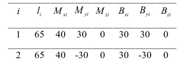
(1)Table 1 represents the design parameters for the proposed mechanism in Fig. 2. Moreover, 50 cm and the minimum and maximum elongation of each prismatic actuator are 2 and 35 cm, resulting in a 33cm stroke.
Table 1: design parameters of the proposed mechanism in Fig. 2. All dimensions are given in cm.
. Inverse Kinematics Problem
To solve the IKP, the kinematic loop-closure is written for a given limb:
i
v
if
i0
ρ
(2)wherefi Qbi h ri. In the above equation, vi is the vector connecting Ai to Bi. Also, ri and irepresent respectively the position of the Mi point and the position of the slider relative to Mi in the reference frame. Also,
i
b is the position of point Biin the moving coordinate frame. The IKP can be obtained by isolatingvifrom the above and taking the norm of both sides as follows:
(
)
T T
i i
i
i i
iv v
f
ρ
f
ρ
(3)Upon expanding the above and notations of ei and efi as unit vectors along i and fi, the following equation is obtained:
2 2 2
2
0
i
i
ie
ρi
e
f
f
i
l
iρ
ρ
(4)
2 2 2i i
i
f
ie
ρi
e
f
l
i
f
ie
ρi
e
fρ
(5)Finally, Eq. (5) is the solution of the IKP, which has
2
2 4 solutions referring to as the four working modes of the mechanism.
5. Forward Kinematics Problem
Several methods are available to solve the FKP of the parallel mechanisms [2, 3]. Here, the elimination theory is adopted which is based on the so-called resultant technique. The position of point Bi in the fixed coordinate frame can be written as:
*
,
1, 2
i
ii
b
h Qb
(6)Where
i li Mxi Myi Mzi Bxi Byi Bzi
1 65 40 30 0 30 30 0
* 1
30cos
30sin sin
30cos
50 30sin
30cos sin
b
(7)* 2
30cos
30cos sin
30cos
50 30sin
30cos sin
b
(8)If vector ai is subtracted from both sides of Eq. (6), then one has:
*
i
i i
i,
i
1, 2
b
a
h Qb
a
(9)Where
1
1 1
40
cos
/ 9
30
sin
/ 9
0
a
(10)
2
2 2
40
cos
/ 9
30
sin
/ 9
0
a
(11)Taking the Euclidean norm of each side of Eq. (9), we get:
* 1
* 1
* 1
1 1 1
2 2 2
2 1
a a a
b b b
x
x
y
y
z
z
l
(12)
*
*
*
2 2 2
2 2 2
2 2 2
2 2
a a a
b b b
x
x
y
y
z
z
l
(13)It should be noted that tan-half substitution of angels and is used in order to simplify Eqs. (12) and (13) [4]:
2
2 2
2
1
tan
, sin
, cos
2
1
1
t
t
t
t
t
(14)2
2 2
2
1
tan
, sin
, cos
2
1
1
p
p
p
p
p
(15)Finally, two equations are obtained as experssed in terms
of t and p, which are respectively 1 and 2. Reaching this step, the so-called resultant method should be applied
to 1 and 2 in order to obtain a univariate expression by eliminating either t or p. Thus, upon applying the following, p can be eliminated which results in a
12
Res
1,
2, p
(16)In the above equation, Res( 1, 2,p), stands for the resultant of two polynomials
1and
2where thecommon variable p is eliminated. It should be noted that the resultant technique is implemented in almost all computer algebra systems, such as Maple and Mathematica, and it can readily used. It can be easily
shown that
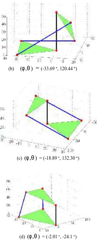
12 is an eighth-order univariate polynomialexpression with respect to t. According to Eq. (16), it can be confirmed that the upper bound of the number of solutions for the FKP is eight, which are the right assembly modes of the mechanism. By trial and error, for a given set of actuator elongations, namely 14 and
1 12
, the upper bound of the number of real solutions was not more than four. Fig.3depicts schematically four assembly modes for the latter actuator elongation. From Fig. 3, it is obvious that only Fig. 3(d) is mechanically realizable [5].
6. Workspace
There are several methods for finding the workspace of a mechanism. In this paper, the interval analysis method is used. This method has the advantages of being able to deal with almost any constraint and any number of DOFs and is proved to be efficient in computing the most difficult cases of 6-dimensional workspaces. Interval analysis is an appropriate mathematical tool for solving the workspace of robots [6, 7]. Moreover, when uncertainties are present in the joint space of a robot, interval analysis can be regarded as a promising solution to analyze the kinematic properties of that robotic mechanical system. In this paper, IntpakX, a package implemented in Maple, is used [8, 9]. The following equation was obtained from the inverse kinematics section:
(b) ( , )
=
(-33.69 , 120.44 )(c) ( , ) = (-18.89 , 132.30 )
(d) ( , ) = (-2.01 , -24.1 )
Fig. 3: Different solutions for the FKP, assembly modes, for 14
and 112. The Units of all axes are in cm. 2
0
i i i i i
a
b
c
(17)Where
2 21,
2
,
i
i i i i i
a
b
e
e
fc
e
l
iρ (18)
2
4
2
i i i i
i
i
b
b
a c
a
(19)As IntpakX does not work properly with equations possessing square roots it may not converge rapidly. To circumvent this problem, both sides of Eq. (19) are squared. So, by considering the stroke of the actuators, one has:
2
,min ,min
2
,max ,max
0
0
i i i i i
i i i i i
a
b
c
a
b
c
(20)Finally, the problem of finding the workspace is reduced to solving the system of inequalities represented in Eq. (20).
6.1. Interval-based Determination of the Workspace Table 2 represents the pseudo-code for the algorithm used in this paper. As the first step, an initial range for and as input boxes are placed in the list w. The algorithm will determine the sets of boxes which are
stored in
w
in,
w
out andw
b. The boxes ofw
in satisfy all the workspace requirements, Eq. (20), constituting thefeasible workspace of the moving platform. Also,
w
out represents boxes which do not satisfy Eq. (20) for one leg or two legs. Finally, boxes, which cannot be guaranteedto be a solution, are added to
w
b [10, 11]. The proposed algorithm in Table 2 follows this process until the width of blue boxes is more than a given threshold
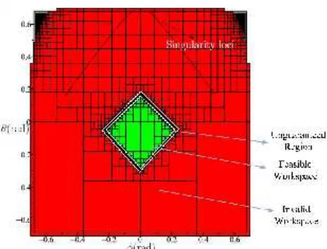
. Fig. 4 shows the workspace of the proposed mechanism with design parameters presented in Table 1.Table 2: pseudo-code for obtaining the workspace of the pm under study in Fig. 2.
1: Loop
2: Initialize list w including initial input boxes (
Β
i)3: Initialize the empty lists
w
b,w
out andw
b 4: IfΒ
isatisfies Eq. (20)5: Store
Β
ito the end of listw
out, go to 46: Else
Β
iis added to the end of listw
out, go to 4 7: If (the width of box (Β
i) > )8: Bisect
Β
ito the two new boxes added to the endof list w
9: Else If (the width of boxes exceed a given
threshold)
10: Store
Β
ito the end of listw
b11: End If
12: End If
13: End Loop
Fig. 4: Workspace and singularity locus of the proposed mechanism. Fig.2, based on the design parameters presented in Table 1. 7. Singularity Analysis
Singularity of the PMs is based on the regularity of some Jacobian matrices coming from the first-order kinematic relation. In order to obtain the Jacobian matrix of a manipulator, several methods are reported in the literature such as screw theory [12, 13, 14]. Finding the Jacobian matrix via screw theory is based on the concept of reciprocal screw, which is beyond the scope of this paper and only final results are provided. In short, the screw reciprocal to an R joint is the one which crosses the axis of the R joint, while the reciprocal screw to a P joint is the one whose axis is perpendicular to the direction of the P joint. To do so, first, the Kinematical Screw System (KSS) of all the limbs constituting the mechanism should be obtained. In fact, the KSS pertains to finding a set of screw reciprocals to the screw system of a limb. The next step consists of finding the constraint imposed on the moving platform by the limbs. It can be done by applying the concept of the reciprocal screw system to the KSS of all the limbs. Finally, each row of the Jacobian matrix can be computed by resorting again to the concept of reciprocal screw and obtain the corresponding KSS by locking the actuators. Following the above reasoning, and skipping some mathematical derivations, one can obtain the following Jacobian matrix:
*
1 1 1 1
*
2 2 2 2
1 2 1 2
6 6
$
,
K
e
0
e
0
0
e
e
0
e
e
0
0
0
0
0
0
v
b v
v
b v
i
i
j
j
k
k
(21)
*
1 1 1
*
2 2 2
1 1 4 1
1 2
2 1 4 2
4 1 4 1 4 4 4 1
6 6
0
0
0
0
0
ψ
0
x
y
z
0
e
e
0
0
0
0
0
v
b v
v
b v
ρ
ρ
i
j
k
(22)
where
e
1ande
2are respectively thex
-axis andy
-axis. Preferably, singularity locus should be out of the workspace to obtain a singularity-free workspace. The singularity locus is the configuration of the mechanism in which the determinant of Jacobian matrix vanishes:
det K 0 (23)
The determinant of the Jacobian matrix is a function of and. Fig. 4 illustrates the singular configurations with respect to and where, from the latter figure, it can be inferred that the mechanism has a singularity-free workspace.
8. Sensitivity Analysis
As mentioned in [15, 16], the maximum kinematic sensitivity is defined as the maximum error occurred in the Cartesian workspace as a result of bounded displacements in the joint space that can be mathematically expressed as follows:
,
max
1, and
,max
1c f c f
c c
f
r p
p
f
ρ ρ (24)
where is a small rotation displacement of moving platform, is a small actuator displacement, and c and f are constraint norm and objective function norm for kinematic sensitivity, respectively. Equation (24) provides tight upper bounds of the end-effector rotation and point-displacement under a unit-magnitude vector of actuated-joint errors. In the PM, there is only rotational displacement; hence only rotational displacement sensitivity has to be studied. As previously investigated in [15, 16], based on different combinations of c and f, four different indices are possible for representing the kinematic sensitivity of a PM. From the latter studies, it follows that
,2
r
and,
r
are the most reliable indices for representing the kinematic sensitivity. The proposedapproach is as follows: if 1
c
is considered, then it
follows that 1
c
DOF is equal. To obtain every vertex, the above constraint can be rewritten:
2
Δ
1
nL x
(25)
Where
T 2
2
and 1
1 1
1
T T
T n
n
L
K
K
(26)Also, represents the component-wise inequality. For
obtaining the vertices, m independent equations of Eq.
(25) should be solved. To this end,
,2
r
and,
r
arecomputed as follows:
,
max max , max
1, ,4 1, ,4max max
1, ,2, max
1, ,2r i i i i
i i i i
(27)
,2
2 2 2 2
1, ,4 1, ,2
max
max
r i i i i
i i
(28)
The polyhedral is symmetrical with respect to the origin; thus it suffices to compute only half of the vertices. Here, kinematic sensitivity is defined in the terms of tan( / 2)
andtan( / 2) . To achieve this purpose, the Jacobian matrix is computed for every single point in the workspace. Then, Eqs. (27) and (28) are solved by substituting the Jacobian matrix into Eq. (25). Fig. 5 represents the values of
,2
r
and,
r
within the workspace. From the latter figure, in the case that the kinematic sensitivity of the mechanism is compatible with,2
r
, which is the worst situation, the maximum error will be 0.03 for the whole workspace. Thus, it can be concluded that the mechanism is designed properly with regard to purposes of the simulator under study in this work. As it can be observed from Fig. 6,,2 ,
r r
which is consistent with the results obtained in [32].Fig. 7: The proposed indices computed for the kinematic sensitivity of the mechanism.
9. Conclusion
This paper investigated the conceptual design, the kinematic properties and the architecture of a 4-DOF serial-parallel driving simulator for large commercial vehicle driving simulators. Then, the kinematic properties of the parallel part of the mechanism including IKP, FKP, workspace, singularity, and kinematic sensitivity were analyzed. The elimination theory was used to solve the FKP by resorting to the resultant technique, which resulted in eight assembly modes. The interval analysis was used for obtaining the workspace. The singularity loci were obtained, which led to a singularity-free workspace. Finally, the kinematic sensitivity of the parallel part was computed to find the maximum error in the task space for a set of unit errors in the joint space. To
this end, two indices
,2
r
and,
r
were used. Future works include dynamic modeling of the mechanism and the kinematic sensitivity of the mechanism by considering error in the passive joint. The stiffness analysis of the mechanism should be worked out as well.Acknowledgment
The authors would like to acknowledge Mr. J. Tashakori Hashemi, Mr. P. Sanandaji and his colleagues from Tehran Municipality, Mr.M.Naseri CEO of AKIA DUICH, Mr. A. Akbarinrad CEO of OGHAB AFSHAN, and M.R. Ashouri at the Virtual Reality Laboratory of K.N. Toosi University of Technology. Special thanks are also given to F. Anooshahpour, H. Tehranchian, M. Lagha, M. Hemmatabadi, and S. Samiezadeh for their insights in the conceptual design.
References
[1]S. Advani, The Kinematic Design of Flight Simulator Motion-Bases, PhD Thesis, Delft University of Technology, (1998).
[2] J. Slob, State of the Art Driving Simulators, a Literature Survey, Eindhoven University of Technology Department Mechanical Engineering Control Systems Technology Group, ( 2008).
[3]J. Greenberg, R. Curry, M. Blommer, K. Kozak, B. Artz, L. Cathey and B. Kao, The Validity of Last-Second Braking and Steering Judgments in Advanced Driving Simulators DSC2006, Driving Simulator Conference, Paris, France, (2006).
[4] A. Huesmann ,J. Nauderer, Applications to Driving Simulation and Their Requirements to the Tool, Motion Simulation Conference, Braunschweig, (2007).
Simulator, in Driving Simulator Conference, Michigan, US, (2003).
[6]J. Challen, Reality Bytes, Driving Simulators, (2008) 50-53.
[7] Lander Simulation and Training Solutions Tutor, Available: ttp://www.landersimulation.com, (2008).
[8] Nasir Virtual Reality Driving Simulator, [Online]. Available: http://www.DrivingSimulator.ir.
[9] F. Anooshahpour, A. Nahvi, N. Mehrabi, A. H. Haghighi, R. Kazemi, and S. Samiee, Design and Implementation of a Modified Classical Washout Filter Algorithm for ASARun Driving Simulator, ISME, (1) (2010)1-7
[10] I. A. Bonev, and J. Ryu, A Geometrical Method for Computing the Constant-Orientation Workspace of 6-PRRS Parallel Manipulators, Mechanism and Machine Theory, 36(1) (2001)1-13.
[11]M. Tale-Masouleh, M. H. Saadatzi, C. Gosselin, and H. D. Taghirad, A Geometric Constructive Approach for the Workspace Analysis of Symmetrical 5-PRUR Parallel Mechanisms (3T2R), Proceedings of the ASME, International Design Engineering Technical Conferences, (2010).
[12] D. Chablat, and P. Wenger, Moveability and Collision Analysis for Fully-Parallel Manipulators, Proceedings of the Theory and Practice of Robots and Manipulators Symposium, RoManSy, (1998).
[13]E. J. Haug, F. A. Adkins, and C. M. Luh, Operational Envelopes for Working Bodies of Mechanisms and Manipulators, Journal of Mechanical Design, 120(1) (1998)84-91.
[14]J. P. Merlet, Parallel Robots, Springer, (2006).
[15] J. P. Merlet, Solving the Forward Kinematics of a Gough-Type Parallel Manipulator with Interval Analysis, The International Journal of Robotics Research, 6(3) (2004)281-290.
[16] T. Yoshikawa, Analysis and Control of Robot Manipulators with Redundancy, Robotics Research: The First International Symposium, (1984)735-747.
[17]J. K. Slisbury, and J. J. Craig, Articulated Hands, The International Journal of Robotics Research, 1(1) (1982)4-17.
[18] P. Cardou and S. Bouchard and C. Gosselin, Kinematic Sensitivity Indices for Dimensionally
Nonhomogeneous Jacobian Matrices, IEEE
Transactions on Robotics, 26(1) (2010) 166-173.
[19] R. J. Telban, and F. M. Cardullo , Motion Cueing Algorithm Development:Human-Centered Linear and Nonlinear Approaches, The NASA STI Program Office, State University of New York, Binghamton, New York, (2005).
[20] L. D. Reid, M.A. Nahon, Flight Simulation Motion Base Drive Algorithms, University of Toronto, UTIAS report, (1985).
[21]M. Tale-Masouleh, C. Gosselin, M. Husty, and D. R. Walter, Forward Kinematic Problem of 5-RPUR Parallel Mechanisms (3T2R) with Identical Limb Structures, Mechanism and Machine Theory, (2011) 945-959.
[22] M. Tale-Masouleh, C. Gosselin, M. H. Saadatzi, X. Kong, and H. D. Taghirad, Kinematic Analysis of 5-RPUR (3T2R) Parallel Mechanisms, Meccanica, 3(1) (2011)131-146.
[23] C. M. Gosselin, and J. P. Merlet, The Direct Kinematics of Planar Parallel Manipulators:Special Architectures and Number of Solutions, Mechanism and Machine Theory, 29(8) (1994)1083-1097.
[24]J. P. Merlet, Direct Kinematics and Assembly Modes of Parallel Manipulators, The International Journal of Robotics Research, (1992).
[25] R. E. Moore, R. B. Kearfott and M. J. Cloud, Introduction to Interval Analysis, The Society for Industrial and Applied Mathematics, (2009).
[26] W. Kramer, I. Geulig, Interval Calculus in Maple: The Extension IntpakX to the Package Intpak of the Share-Library, University of Wuppertal, Germany,
Available from
http://www.math.uniwuppertal.de/wrswt/literatur.htm l, (2001).
[27] Maple Application Center, [Online]. Available: http://www.mapleapps.com.
[28] F. Hao, and J. P. Merlet, Multi-Criteria Optimal Design of Parallel Manipulators Based on Interval Analysis, Mechanism and Machine Theory, (2004)157-171.
[29] C. M. Gosselin, J. Angeles, Singularity Analysis of Closed-loop Kinematic Chains, IEEE Transactions on robotics and automation, 6(3) (1990)281-290.
[30] S. A. Joshi, L. W. Tsai, Jacobian Analysis of Limited-DOF Parallel Manipulators, Transactions of the ASME, 124 (2002)254-258.
[31]X. Kong, and C. Gosselin, Type Synthesis of Parallel of Mechanisms, Springer, (2007).
Amir Jaberi obtained his undergraduate degree in Mechanical Engineering at K.N. Toosi University of Technology in 2012 and also received the M. Sc. degree in the major of Applied Design from University of Tehran. Now, he is a Research Associate in Control Lab in University of Tehran. In his B.S. thesis, he worked on conceptual design and kinematic analysis of an urban bus driving simulator. His research interests include kinematics and dynamics of parallel mechanisms, haptic interfaces, driving simulators.
Ali Nahvi received the Ph.D. degree in Mechanical Engineering from the University of Utah in 2003. He is currently a faculty member at K.N. Toosi University of Technology in Iran. He is the recipient of Anton Philips Paper Award in 1998. His research interest is in the area of virtual reality, design and control of driving simulators, haptic interfaces, and virtual laboratories.
Milad Hasanvand did his undergraduate in Mechanical engineering in Chamran University of Technology (2008), and also received his masters in Mechanical engineering from K. N. Toosi University of Technology (2011). His academic background and interests are in different fields of the interdisciplinary field robotics, he has worked on the kinematics, dynamics, and control of serial and parallel mechanisms. He also has worked as a TA for courses like Advanced dynamics and virtual reality.
Mohammadreza Arbabtafti received a B.S. degree in Mechanical Engineering in 2002 from Isfahan University of Technology, Iran. He received his M.S. and Ph.D. degrees in Mechanical Engineering in 2004 and 2010 from Tarbiat Modares University, Iran. He is a recipient of Khwarizmi Young Award 2008. He is currently on the faculty of Shahid Rajaee Teacher Training Univeristy in Iran. His research interest is in the area of haptics and robotics.
Mehdi Tale Masouleh received the B. Eng. M. Sc. and Ph.D. degrees in Mechanical engineering (Robotic) from the Laval University, Québec, Canada, in 2006, 2007 and 2010, respectively. He is
currently a faculty member of Faculty of New Sciences and Technology of University of Tehran. He is also the director of Human-Robot Interaction Laboratory, known as TaarLab for its Persian abbreviation. His research interests are kinematics, dynamic and design of serial and parallel robotic systems, Humanoid, mobile robots and optimization techniques (interval analysis and convex optimization ...) for robotic applications. He is also director of a national-level project for a haptic dental simulator.
![Fig. 3, it is obvious that only Fig. 3(d) is mechanicallyrealizable [5].](https://thumb-us.123doks.com/thumbv2/123dok_us/8945224.1854592/4.612.56.293.527.607/fig-obvious-fig-d-mechanicallyrealizable.webp)