International Journal of Automotive Engineering Vol. 6, Number4, Dec2016
E. Khanmirza
1, H. Darvish
1, F.Gholami
1, E.Alimohammadi
11. School of Mechanics, Iran university of science and technology, Narmak, Theran, Iran
Abstract
Accurate and correct performance of controller in cruise control systems is important. Hence, in such systems, controller should optimize itself against noise and probable changes in system dynamic. As a matter of fact, in this article three approaches have been conducted to-ward this purpose: MIT, direct estimation and indirect estimation. These approaches are used as controllers to track reference signal. First the performance of each of these three controllers is checked. comparison of performances indicated better behavior for indirect estimation than others. Also, it has less sensitivity against external noise. Finally, by using indirect estimation method as an adaptive control approach, two parallel separate controllers are designed for two inputs, gas and braking, and their performances are compared with recent studies. It shows improvement in performance of adaptive cruise control system to track reference signal.
Keywords: Intelligent transportation system, Longitudinal control, Adaptive cruise controller, Indirect estimation.
Introduction
Because of increasing number of vehicles, traffic has gone to be jam and number of accidents have increased. So, many researchers have tried to use control algorithm in order to decrease accidents.
These researches cause revolutions in ’advanced driver assistant systems’ (ADAS). About 90% of accidents are affected by the human error, poor judgment or distraction of driver or less perception about spot where vehicle is located [1]. Many car factories are inclined to control their products to prevent accident, so they have used ’adaptive cruise control’ (ACC) in their expensive models and they have tried to use this controller in mid-range cost of their products. ACC is used to keep safe distance between vehicles [2, 3].
Before ACC, there was ’cruise control’ (CC) which is used in luxury vehicles. Cruise control systems had been used to achieve the desired speed that was selected by driver. Cruise control was useful when the driver was driving in long and retired street but it was not intelligent. If there is an obstacle on the road, the controller
can not change speed and collision occurs. Also, if the front vehicles reduce their speed the host driver must change desired speed. So, ACC was introduced to overcome these problems. In ACC systems, a sensor was used to detect front vehicle and estimate relative velocity between host velocities and front vehicle.
First challenge was designing such sensors to detect front vehicle in different weather and with the suitable accuracy. So, many technologies have been tried to take part in ACC systems developments.
But two of them are useful than other, millimeter-wave radar and light detection and
ranging [4].
First generation of ACC was not useful because these models couldn’t adjust on braking system and It adjusted only on throttle. When the velocity of vehicles were under 30km=h the controller didn’t work well. Hence, when the traffic was going to be jam, the drivers couldn’t use these models of controllers. This was a defect of first generation of ACC systems [5]. Research on braking system which could
cooperate with ACC resulted in Stop & Go controller [6].
Based on performances, ACC can be divided to two part:
1- Safety: Means to keep safe distance between host and front vehicle by tracking signal reference in order to prevent collision.
2. Comfort: Controller designs commands which cause less acceleration as much as possible to keep safe distance.
ACC systems can be divided to many parts. One part is sensor; sensors collects information, such as distance and relative velocity between host and front vehicle. One of the most important parts of this controller is signal reference. To achieve signal reference we should consider:
1- Safety distance.
2- Relative speed for host vehicle.
3 Acceleration or deceleration for the host vehicle (If required).
In many researches like [7, 8] authors have designed controller to track acceleration and deceleration without considering initial condition. Such researches represent that the difference between signal reference and initial condition was very low when the controller had started, so their system was stable. If the difference between signal reference and initial condition is large, will result in collision.
In recent works, fuzzy controllers have been used to control speed of vehicle in cruise control. There are many approaches to design slave-loop controller, and fuzzy controller is one of the suitable choices in which [9] has been used to prevent collision. Because human logics can be converted into fuzzy rules easily. With fuzzy controller, acceleration and deceleration forces can model human behavior. It is the main advantage of this type of controller. However, fuzzy controller consists of three main types, fuzzifier, inference engine and defuzzifier. With membership functions, first real values in fuzzy controller will be converted to fuzzy values .Fuzzy values describe the intensity of real values in each membership that are between one and zero. In inference part, with some fuzzy rules, output fuzzy values are obtained. By defuzzifier part, this fuzzy values will be converted to output real values and output of fuzzy controller will be achieved. Selecting appropriate fuzzy membership function and their intervals can affect output of fuzzy controller that works. In [10] genetic algorithm has been used to optimize fuzzy membership functions and achieve acceptable intervals by considering
both safety and comfort constraints. Another use of fuzzy controller is in [11], that reduces disturbance of transition between cruise and adaptive control. Also in [12], to achieve smoother acceleration and deceleration not to exceed safe relative distance, a fuzzy controller has been used.
In recent studies, neural network have been used too. For example, in [13], by obtaining difference values of real and reference signal, network was trained to produce proper acceleration and deceleration forces in several driving situation. In that research three neural networks, ’back propagation network’ (BPN), ’radial basis network’ (RBN) and ’generalized regression neural network’ (GRNN) have been introduced to use as slave-loop controller in ACC systems. Investigated results of that research showed that BPN network works better in satisfying safety constraint and RBN works better in satisfying comfort constraint. There are some other approaches in design of slave-loop controller. [14] is one of them that used a supervised controller in ACC systems. Beside considering all types of mentioned controllers, PID (proportional integrated derivative) controller is more popular and practical in ACC systems, because of some advantages of this controller, such as simplicity in implementation, low noise, low sensitivity and attenuation of disturbance. Many studies such as [15, 8] used this type of controller in salve-loop controller of ACC systems.
Wheel friction of vehicles, changing the number of passenger and the amount of applied load in vehicles may cause changing in vehicles dynamic. Also, when the braking system of vehicle becomes old or by using it more than usual (because of hotness in it), it may cause changing in dynamic and transfer function. In cruise control systems, controller has the task to order appropriate command in order to track reference signal. However, probable changes in dynamic and transfer function of the system can cause problems for the designed control system and as a result irreparable damages will be emerged. Hence, in this article using adaptive methods to control adaptive cruise control systems is suggested and the performances of such systems are checked.
In the past, there were different approaches to control ACC systems, but adaptive control methods have not been used yet. In this article three adaptive method are suggested to control ACC systems: MIT, direct estimation and
International Journal of Automotive Engineering Vol. 6, Number 4, Dec 2016 indirect estimation. By checking the
performances of these methods, it was found that indirect estimation method acts better in tracking reference signal. Also, it has less sensitivity against external noise. Hence, by using this method, two parallel separate controllers for two inputs, gas and braking, were designed and the performance of suggested method was checked. Comparison of that method with non-adaptive methods shows improvement in controller performance to track reference signal.
Reference signal
ACC models can be divided into three parts: 1) sensor 2) signal reference 3) desired acceleration or desired deceleration. One of the most important parts of ACC systems is to calculate the safe distance between vehicles. As a matter of fact, several approaches have been conducted towards this purpose. Some articles, [16, 17], have tried to determine safe distance by simulating imitating of human behavior in the time of making immediate decision, so the ACC produces more appropriate commands to achieve driver performance. Although this approach has its own advantages, it has been considered not to be safe due to uncontrollable driver’s behavior in the time which immediate respond is required. Another approach is time headway which is used by the driver and needs at least 2s to make appropriate reaction [18]. In this approach (2 − s headway rule) the relation of vehicle has been expressed by linear Eq. (1) and by comparing this value with distance between vehicles. The controller makes decision, only if the difference between these values is of significance. Subsequently, the controller will send commands to accelerate or decelerate and if there is not any vehicle in front of the host, the controller will send commands to achieve the desired speed that has been applied by driver.
(1)
In Eq. (1), is the time which should be chosen for rule, and explains the minimum distance between vehicles in the moment that the front vehicle is stopped. also is the absolute velocity of host vehicle.
rule is one of the most useful
approach in ACC systems which has been used in many researches. However, in this approach there is only one parameter to tune, time headway. On the other hand, there is no limit for
braking force and comfort of passengers has not been taken into account. In many studies, researchers assumed that the time headway is constant. In order to deal with this problem in [19], an approach has been suggested, called model reference. They have also investigated the relation of host velocity of vehicle and relative distance with time headway approach.
They have shown that if the velocity of vehicles are low, the results of both approaches (time headway and model reference) are approximately equal and if the velocity of vehicles are high, the results between linear and nonlinear (model reference) are different. Also, they have reported three zones in model reference approach to control vehicle. These are: 1) safe zone 2) critical zone 3) stop zone. These zones are shown in figure1.
For extracting the unknown parameters of the model, these zones have been considered as boundary conditions in the nonlinear relative acceleration of the model. Every zones of this model is defined for the host vehicle to maintain a specific speed. In the safe zone, the host vehicle is allowed to maintain each speed that is chosen by the driver, like the old cruise control system. But when the host vehicle reaches the critical zone (d0 in the critical zone), to prevent the collision between vehicles, the host vehicle speed should be decreased based on the relative distance and approaches in the reference signal. In the stop zone, the real speed of vehicle should be zero and a small gap between vehicles should be considered when the leader vehicle has stopped. Another difference between reference model and time headway model is the maximum braking force, which has been considered in the reference model.
So in the reference model, an unknown parameter exist that should be solved in this condition. This can cause the relative distance that is designed on the maximum braking force. The value for the maximum physical braking force of the host vehicle can be obtained from the physical conditions of each vehicle. However, the boundary conditions of the reference signal can be considered as:
In the boundary section of the safe and critical zone, the host vehicle speed is considered as the driver preset velocity, .
In the boundary section of the critical and stop zone, the host vehicle velocity is considered zero.
In the reference signal, the maximum braking force cannot exceed from specific value.
The relative acceleration relationship of the host and leader vehicle of the reference model is shown in the Eq. (2). and are the relative distance between vehicles and the situation of the leader vehicle respectively. is the minimum safe distance of the model and depends to the cruise speed of the driver and maximum braking force, like c which acts as damping force to decrease the speed of the host vehicle. These two parameters can be solved from the boundary conditions of zones and the maximum physical braking force. The nonlinear function in the acceleration equation has been considered as second order polynomial sentences too.
(2) In [19] authors solved the differential equation of the acceleration relationship analytically and achieved the unknown parameters. The final relationship between host vehicle and the relative distance with known parameters is shown in Eq. (3).
(3) Where √
Note that is constant and is reference velocity.
Instead of considering more details in the reference model, this model has the advantage of achievement with dynamical equation not like the stationary one, the time headway model. But some disadvantages in this model exist, like not considering the road conditions and traffic loads which can be considered as an external condition in providing a more suitable reference signal. After choosing a suitable reference signal, applying this signal to the engine and braking of the host vehicle cannot be done instantly, especially because of nonlinearity in those parts of vehicle. Consequently, an advanced controller should be designed to solve this problem. Already, researchers did not consider initial condition effect on cruise control system. So, Mohtavipour and his co-workers modified signal references by considering initial condition to achieve better performance of cruise control system when the system is not in stable state [20]. They used initial condition to produce signal reference. Their signal reference is reported as equation (4):
(4) In equation (4), and are front vehicle velocity and host vehicle velocity. b is a constant that is obtained from . Also, a is constant that with the basis e form forgetting factor. According to [20], in this research a, b are 0.005 and 0.05.
Methods
In this part, authors showed the methods which are used in the following of article [21].
Estimation
According to the approaches that is used in this article, due to the varying system, in each point, model and controller parameters should be estimated. So at first, estimation algorithm is explained. Suppose that the system is describable with equation (5).
Where A and B are functions of leading operator (q), that the system performance depends on them. u(t) and y(t) are input and output of the system. Assume v = 0:
The degree of A is n and m is the degree of B. m is (degree of (A)-d0) so that d0 is called excess of poles. If we use delay operator (q−1) in equation ( ), we will have:
In the following, model was assumed as linear in parameters, so
Where
The least-square estimator with exponential forgetting factor (λ) is given by
To converge the estimations to the true values, we should choose compatible estimation (5) = ̂ ̂ ̂ (6)
International Journal of Automotive Engineering Vol. 6, Number 4, Dec 2016 model and input must be sufficiently rich. We
should notice that (max (n, m + d0)) sampling time must take before the regression (ϕ) vector is defined. For deterministic case n + m + 1, sampling time must take larger amount (max (n, m + d0)).
1. INDIRECT SELF-TUNING
REGULATORS
By combination ’recursive least square’ (RLS) and ’minimum degree pole placement’ (MDPP) approaches, indirect self-tuning algorithm will be obtained. If the desired closed-loop model is , following steps should be
done:
According to the estimation algorithm, polynomials A and B should be estimated.
Suppose the control law is . Based on the normal input uc and by using (MDDP), amounts of R, T and S will be calculated.
By using equation , control variables will be calculated.
Note that above steps should be repeated in each step of sampling.
2. DIRECT SELF-TUNING REGULATORS
In this part, authors described the equations that help to reduce calculation in controller design. Final results will be used to estimate the controller parameters instead of model parameters. So consider process model that was described by Eq. (5) without any disturbance (v = 0):
If the desired response is given by
To reparameterize process model parameters in the term of controller, Diophantine equation is considered as an operator identity and let operate on y(t).
This gives
Hence,
So, if we consider this equation as process model, B−, R, and S will be estimated. Hence, the control law will be obtained directly without any calculation to estimate original model.
Note that this equation is nonlinear, because (B−) and latest parentheses are polynomials and it cause nonlinearity, but if the system be minimum phase, by assuming b0 is constant it can change nonlinear equation to linear equation.
3. The MIT RULE
Suppose that the desired model is available and is desired output, y is the model output and error is . If a controller with regulator parameter θ exists, we can reduce error by changing θ amounts. Different functions may be suggested to reduce error, for example:
In order to reduce (10), we should change θ amounts in the opposite direction of error function increscent. So,
In which
is called sensitivity derivative and it shows how variation of θ affects error function.
Note that in simulation, λ = 0.5.
4. Vehicle Model
The following transfer function is represented to explain longitudinal dynamic of vehicle that is under the effect of two inputs, braking or gas and land slope, which delays of input gas and braking is equal .
is rotational equivalent inertia and is torque coefficient due to sliding friction. Represents gas input and represents braking input.
By looking at the transfer function, it is seen that there are three inputs and one output. One of the inputs is theta. Because we cannot change this input, we can assume that it acts as disturbance. After calculating the transfer function with nominal value which are reported
in Table1, we have:
(7) (8)
It follows from that
(9) (10) (11) (12)
By letting , discrete transfer function will be
5.1.2. Direct controller: For designing controller with direct method,
like indirect one, desired model is needed. In this section, desired transfer function is used in Eq. (16)
Fig1. . Safe, critical and stop zones in reference model.
Table 1 Parameters
Parameter Value
M 1626(kg)
J 4.5(kg/m2 )
R 0.3m
Cf (0.1Nm/rads−1)
τes 0.2s
τbs 0.2s
0 0.5 1 1.5 2 2.5 3 3.5 4 4.5 5
Fig2. Two first figures show estimation of system parameter and third figure shows angular velocity as output and the fourth shows percent of gas pedal as input. (Indirect Method).
(13)
(14)
International Journal of Automotive Engineering Vol. 6, Number4, Dec2016
Fig3. These figures show estimation of controller parameters (Indirect Method).
0 0.5 1 1.5 2 2.5 3 3.5 4 4.5 5 Time(s)
Fig4. First figure shows angular velocity as output and next one shows percent of gas pedal as input (Indirect Method).
Fig5. First figure shows angular velocity as output and next one shows percent of gas pedal as input(MIT Method).
Fig6. . Simulation model that is designed to track signal reference.
0 0.5 1 1.5 2 2.5 3 3.5 4 4.5 Time(s)
Fig7. These figures show angular velocity as output, gas and breaking pedal as inputs respectively. Index ”b” indicate braking and index ”t” indicate throttle (Indirect Method).
0 1 2 3 4 5 6 7 8Time(s)
Fig8. Estimation of parameters of system with two inputs. Index”b” indicates braking and index”t” indicates throttle. (Indirect Method).
5.1.3. MIT method: In this method, Continuous reference model is used, which has transfer function equation like
(17)
Designing parallel controllers for two inputs
Three constraints should be observed to have a good controller in practice: In practice, braking and gas pedals’ order cannot have a negative value. Originally, gas pedal increases speed and
International Journal of Automotive Engineering Vol. 6, Number 4, Dec 2016 braking decreases it. Therefore, they should be
used and estimated in a parallel way.
Since there is saturation value for each input, it should be considered that the value of each input should not be more than one.
For different speeds in real models, vehicle can vary gear.
So, changing gear and as a result of this, changing transfer function should be considered.
Next, regarding to the discussion mentioned above, and with using indirect method, designing controller for braking and gas pedal will be discussed. Then, considering the aforementioned cases and using indirect method, the controllers of gas and braking pedals have been designed.
1.1 Tracking reference signal
In adaptive cruise control systems, controller try to control the speed of vehicle and a reference signal should be tracked by the system to satisfy safety distance condition. Therefore, the designed controller should track the reference signal, properly. The reference signal used in this paper, is given by Eq. (3)
Where , and are cruise speed, safety distance and the distance between two vehicles, respectively.
To investigate the performance of designed controller, it is assumed that the cruise controller system initiate at following conditions:
To control systems with indirect method, an initial guess of transfer function coefficient is required. Then, those guesses will converge into original value. If those guesses are far from original value, there is possibility that those coefficients do not converge into the original value and cause failure in controlling process, so in this article, this fact is shown. The original values of system are as below.
Firstly, the results were shown in figure (10) with initial guesses as below.
According to the figure (10), system behavior tracks reference signals, which are representative of appropriate performance of adaptive controllers. Initial guesses of (bb1) is changed to bb1 = −1 and the responses of system are shown in figures (9).
As it is shown, the performance of system is not acceptable and it causes collision. The reason of an ineligible response is illogical initial guess. Thus, the system cannot estimate the valid value of parameter. As it is shown in figures (10 - 9), the initial guess can cause an acceptable or unacceptable response. Initial guesses, therefore, should be chosen near the valid values or at least the initial guesses must have the same sign as original values.
Validation
In this part, authors have tried to compare the performance of the controller that has been designed in this article with the controller which was used in [20]. To achieve this goal, authors have used the initial condition and signal reference that was suggested in [20]. These initial conditions are reported as equation (19) and their signal reference is also reported as equation (4).
As it is shown in figure (11), the suggested controller could track the signal reference better than previous controller, and the performance of the system has been improved. It is important to note that because of dependency of reference signal to the vehicle’s velocity, by improvement of controller the signal reference has been refined.
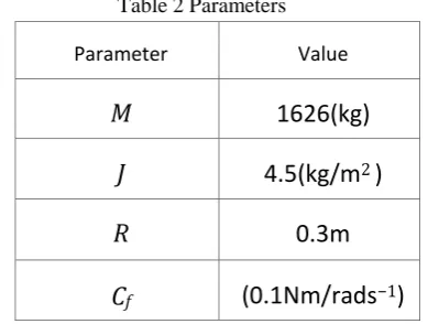
Table 2 Parameters
Parameter Value
M
1626(kg)
J
4.5(kg/m
2)
R
0.3m
C
f(0.1Nm/rads
−1)
(19)
Fig9. This subfigure shows: Velocity as output,gas and breaking pedal as inputs for tracking reference signal and distance between two vehicle.
Fig10. This subfigure shows: Velocity as output, gas and breaking pedal as inputs for tracking reference signal and distance between two vehicles.
Fig11. Comparison between recent result of controller and Mohtavipour result [20].
International Journal of Automotive Engineering Vol. 6, Number 4, Dec 2016
Conclusion
The goal of ACC systems is to track the reference signal. According to the figure (10), the system has tracked the reference signal in a short time, and then with tracking the reference signal, the system prevents a crash with front vehicle. Also, it satisfies all constraints greatly, such as prevention of input signals saturation, existence of positive gas input, and the braking. In figure (2), existence of noise in indirect estimation method leads estimations to have a better convergence. Also, the results by three method show that tracking the reference signal in indirect estimation method has a better performance. Therefore, this method is used in the two-input single-output system. As shown in figure (2), figure (3) and figure (4), the direct method is highly sensitive to noise and noise will worsen convergence in the estimation of controller parameters, but indirect method is more robust against noise that makes better estimation in this method. According to the description that is given in the results section, choosing illogical initial guesses cause decreasing space between vehicles, and then collision occurs, so designers must be careful in choosing them.
References
[1]. George A Peters and Barbara J Peters. Automotive vehicle safety. CRC Press, 2003.
[2]. Hermann Winner, Stefan Witte, Werner Uhler, and Bernd Lichtenberg. Adaptive cruise control system aspects and development trends. Technical report, SAE Technical Paper, 1996.
[3]. Richard Bishop. Intelligent vehicle technology and trends. 2005.
[4]. S Nagappan. Adaptive cruise control: Laser diodes as an alternative to millimeter-wave radars. Ward’s Auto Electronics— September/October, 2005.
[5]. José E Naranjo, Carlos Gonzà, Ricardo Garc´ıa, and Teresa De Pedro. Acc+ stop&go maneuvers with throttle and brake fuzzy control. Intelligent Transportation Systems, IEEE Transactions on, 7(2):213– 225, 2006.
[6]. José E Naranjo, Carlos González, Jesús Reviejo, Ricardo Garc´ıa, and Teresa De Pedro. Adaptive fuzzy control for inter-vehicle gap keeping. Intelligent Transportation Systems, IEEE Transactions on, 4(3):132–142, 2003.
[7]. Behnam Ganji, Abbas Z Kouzani, Sui Yang Khoo, and Mojtaba Shams-Zahraei. Adaptive cruise control of a hev using sliding mode control. Expert Systems with Applications, 41(2):607–615, 2014. [8]. Vicente Milanés, Jorge Villagrá, Jorge
Godoy, and Carlos González. Comparing fuzzy and intelligent pi controllers in stop-and-go manoeuvres. Control Systems Technology, IEEE Transactions on, 20(3):770–778, 2012.
[9]. Wafa Batayneh, Omar Al-Araidah, Khaled Bataineh, and Adnan Al-Ghasem. Fuzzy-based adaptive cruise controller with collision avoidance and warning system. Mechanical Engineering Research, 3(1):143, 2013.
[10].Luciano Alonso and Juan Pérez -Oria. Genetic optimization of fuzzy adaptive cruise control´ for urban traffic. In Fuzzy Modeling and Control: Theory and Applications, pages 255–271. Springer, 2014.
[11].S Paul Sathiyan, S Suresh Kumar, and A Immanuel Selvakumar. Optimized fuzzy controller for improved comfort level
during transitions in cruise and adaptive cruise control vehicles. In Signal Processing And Communication Engineering Systems (SPACES), 2015 International Conference on, pages 86–91. IEEE, 2015.
[12].Raazi Rizvi, Sandeep Kalra, Chirag Gosalia, and Shahryar Rahnamayan. Fuzzy adaptive cruise control system with speed sign detection capability. In Fuzzy Systems (FUZZ-IEEE), 2014 IEEE International Conference on, pages 968–976. IEEE, 2014.
[13].Merry Cherian and S Paul Sathiyan. Neural network based acc for optimized safety and comfort. Int J Comp Appl, 42, 2012. [14].Dongbin Zhao, Zhaohui Hu, Zhongpu Xia,
Cesare Alippi, Yuanheng Zhu, and Ding Wang. Full-range adaptive cruise control based on supervised adaptive dynamic programming. Neurocomputing, 125:57– 67, 2014.
[15].P Shakouri, A Ordys, DS Laila, and M Askari. Adaptive cruise control system: Comparing gain-scheduling pi and lq controllers. tc, 2(1):1, 2011.
[16].Avi Rosenfeld, Zevi Bareket, Claudia V Goldman, David J LeBlanc, and Omer Tsimhoni. Learning drivers’ behavior to improve adaptive cruise control. Journal of Intelligent Transportation Systems, 19(1):18–31, 2015.
[17].Giulio Francesco Bianchi Piccinini, Carlos Manuel Rodrigues, Miguel Leitão, and Anabela Simões. Driver’s behavioral adaptation to adaptive cruise control (acc): The case of speed and time headway. Journal of safety research, 49:77–e1, 2014. [18].Seungwuk Moon, Ilki Moon, and Kyongsu
Yi. Design, tuning, and evaluation of a full range adaptive cruise control system with collision avoidance. Control Engineering Practice, 17(4):442–455, 2009.
[19].John-Jairo Martinez and Carlos Canudas-de Wit. A safe longitudinal control for adaptive cruise control and stop-and-go scenarios. Control Systems Technology, IEEE Transactions on, 15(2):246–258, 2007.
[20].SM Mohtavipour, H Darvish Gohari, and HS Shahhoseini. Improvement of adaptive cruise control performance by considering initialization states. Universal Journal of Control and Automation, 3(3):53–61, 2015.