Paper received: 26.6.2006 Paper accepted: 28.9.2007
Control of the Cutting Forces in Turning by Entry Angle and
Cutting Inserts Geometry
Toma Udiljak* - Stephan Škorić - Damir Ciglar
University o f Zagreb, Faculty o f Mechanical Engineering and Naval Architecture, Croatia
Machinability is assessed by a set o f criteria or machinability functions, the knowledge o f which is needed in optimising the machining process. New cutting tool materials and new concepts o f the machine tools provide new possibilities and cause quantitative changes in machinability functions. This research has studied the cutting forces function, as one o f the crucial machinability functions. The research was done at longitudinal turning o f steel 16MnCr5. Coated carbide inserts fo r roughing and finishing with different inclination angles were used, and tool clamping system has enabled the changes o f entry angle. Obtained results confirm that entry angle and geometry o f cutting insert significantly influence cutting forces especially thrust cutting force.
© 2008 Journal o f Mechanical Engineering. All rights reserved.
Keywords: turning, cutting forces, cutting tool inserts, inserts geometry
0 INTRODUCTION
Main aims o f modem machining processes are productivity, economy, accuracy and quality of machined surface, which are achieved by continuous analysis o f machinability indicators. Machinability is a very complex term, and it is most often described as the basic technological characteristic o f the material and evaluated by a set o f criteria or functions o f machinability. In metal cutting, the basic set of machinability functions include [1] and [2]:
- function o f tool life, - function o f cutting forces, - function surface roughness, - function o f the chip forms.
A p art from the b asic fu n ctio n s, also a number o f additional functions are applied such as temperature, material removal rate, built-up-cutting edge, power, etc.
The study o f the machinability results also in obtaining the guidelines for the development o f the cutting tools. It has contributed to very intensive development o f the cutting tools, particularly in the area o f high-speed machining, hard machining and dry m achining. Im provem ent o f ex istin g and development o f new cutting tool materials, same as the new concepts o f machine tools, provide new p o s s ib ilitie s an d c h an g e q u a n tita tiv e ly the machinability indicators. Therefore, the study o f machinability represents a continuous process [3] to [6].
Force modelling in metal cutting is important for a multitude o f purposes, including design of machine tools, thermal analysis, tool life estimation, chatter prediction, tool condition monitoring etc. Numerous approaches, in orthogonal and oblique cutting, have been proposed to model metal cutting forces with various degrees o f success [7],
1 STUDY OF INFLUENCE OF TECHNOLOGICAL PARAMETERS ON THE
CUTTING FORCES
1.1 Goal, methodology and condition of study
The goal o f the research is to define the cutting forces as the functions o f influencing parameters. Among a great number o f influencing parameters, for this research the major entry angle
(kJ (Fig. 1), machining depth ( a j , feedrate (f), and
g e o m e try o f c u ttin g in sert are se le c te d as independent factors.
The experiment was made in the Laboratory fo r m ach in e to o ls o f F a c u lty o f M ech an ical Engineering and Naval Architecture, University Zagreb, at universal turning machine. Longitudinal turning process has been used, cutting speed 120 m/min, without coolants. A steel for cementation (16M nCr5) was selected. Three different coated carbide inserts have been used:
1) positive cutting insert (A = 0°) for finishing marked as DCMT11T304-FF1 TP2000,
2) negative cutting insert (A = -6°):
a) cu ttin g in se rt for fin ish in g m arked as D NM G150604-FF1 TP2000,
b) cu ttin g in sert for ro u g h in g m arked as DNMG 150604-M5 TP2000.
Tool clam ping system has enabled the changes o f entry angle (Fig. 1). The measurement o f cutting forces was made by three-component measuring device “Kistler 9257B”.
Fig. 1. Scheme o f longitudinal turning with exchangeable (adaptable) entry angle jc
1.2 Research results obtained with positive cutting insert for finishing (A = 0°)
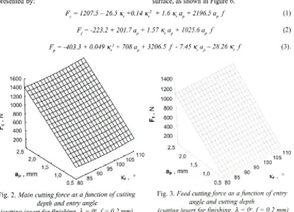
Statistical analysis o f experimental data (SW S tatistica) resulted w ith m athem atical models presented by:
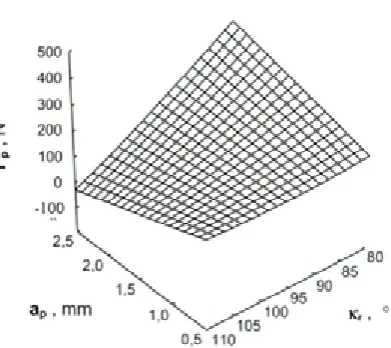
Graphical interpretations o f the obtained mathematical models are presented in Figures 2 to 4.
Figure 2 shows that the main cutting force slightly increases with the increase o f the entry angle. More adequate explanation is obtained by single-factorial analysis, whose results are shown on Figure 5.
Figure 3 shows that feed cutting force also slightly increases by increasing the entry angle even when it’s value exceeds 90°. Such result differs from Kienzle’s formula and can be caused by the same reasons as the increase o f the main cutting force.
Figure 4 shows that passive cutting force is considerably reduced by increasing the entry angle. Furthermore, for certain combination o f cutting data, passive cutting force can take negative values.
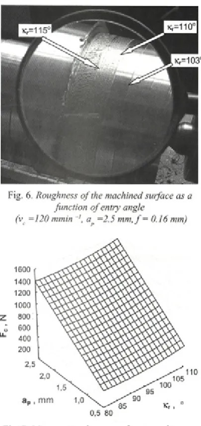
Single-factorial analysis (Fig. 5) shows that significant increase o f main cutting force happens when entry angle exceeds 90°. It is the situation in which contact length between the cutting edge and the workpiece is increased and the end cutting edge angle, k is reduced. As a resu lt there is a significant amount o f friction from three sides, as shown on Figure 1. That fact can be cause o f formidable increase in roughness of the machined surface, as shown in Figure 6.
F = 1207.5 - 26.5 k +0.14 K
2
+ 1.6 k a + 2196.5 a fc r r r p p J
F = -223.2 + 201.7 a + 1.57 k a + 1025.6 a f
/ p r p p J
(1)
(2)
Fig. 2. Main cutting force as a function o f cutting Fig. 3. Feed cutting force as a function o f entry
depth and entry angle angle and cutting depth
Fig. 4. Passive cutting force as a function o f entry angle and cutting depth
(cutting insert fo r finishing, X = 0 ° ,f = 0.2 mm)
Fig. 6. Roughness o f the machined surface as a function o f entry angle
(vc =120 mmin ap =2.5 m m ,f= 0.16 mm)
1600 1500 1400 2 1300 ^ 1200
1100 1000
70 80 90 100 110 120
Kr, 0
Fig. 5. Main cutting force as a function o f entry angle (ap =2.5 mm, f = 0.16 mm) a - positive cutting insert fo r finishing, b - negative cutting insert fo r finishing
1.3 Research results obtained with negative cutting insert (A = -6°)
1.3.1 Cutting insert fo r finishing
Statistical analysis o f experimental data (SW Statistica) resulted w ith m athem atical m odels presented by:
Fig. 7. Main cutting force as a function o f cutting depth and entry angle
(cutting insert fo r finishing, X = -6°, f = 0.2 mm)
Figure 7 shows that by increasing the entry angle, the m ain cutting force is increased. Also, obtained results don’t show significant difference compared to positive cutting insert, except in the area o f greater values o f entry angle. In that area
Fc = 1742.8-38.36 kr +0.21 kr 2 + 1.52 kr p a + 2113.5 a fp J (4)x '
F =-158.12 + 188.43 a + 1.54 / P kr p a + 982.36 a fp J (5)
Fig. 8. Feed cutting force as a function o f cutting depth and entry angle
(cutting insert fo r finishing, A = -6°, f = 0.2 mm)
(Fig. 5) was measured more significant increase of main cutting force, caused by the fact that tools with negative cutting insert (A = -6°) have formidably reduced end clearance angle.
Figure 8 shows that by increasing the entry angle, the feed cutting force is increased even when its value exceeds 90°. Also, obtained results don’t show significant difference compared to positive cutting insert.
Figure 9 shows that by increasing the entry angle, the passive cutting force is form idably reduced. Furthermore, passive cutting force can take n e g a tiv e v alu es for certain cu ttin g data combinations. However, negative values are harder to achieve than using positive cutting insert. This is m ainly consequence o f the fact that tools with negative cutting insert have formidably reduced end clearance angle.
1.3.2 Cutting insert fo r roughing
Statistical analysis of experimental data (SW S tatistica) resulted w ith m athem atical models presented by:
Fig. 9. Passive cutting force as a function o f entry angle and cutting depth
(cutting insert for finishing, A = -6°, / = 0.2 mm)
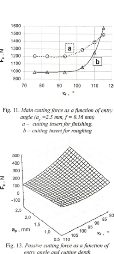
Graphical interpretations o f the obtained mathematical models are presented in Figures 10, 12 and 13. Graphical presentation o f single-factorial analysis o f main cutting forces for negative cutting inserts (for roughing and finishing) as a function of entry angle is given in Figure 11.
Analysis o f Figures 10 and 11 shows that shape o f main cutting force, obtained with cutting insert for roughing, differ in some elements from shape o f main cutting force, obtained with cutting insert for finishing. In the area with lesser values of entry angle and higher values o f cutting depth, measured values o f main cutting force obtained with cutting insert for roughing are smaller. However, in the area with higher values o f entry angle measured values are formidably increased.
Analysis o f Figure 12 shows that shape of feed cutting force, in the area o f all values of entry angle, is similar as for main cutting force.
Analysis o f Equation 9 and its graphical presentation, Figure 13, shows that the increase entry angle, at higher values of cutting depth formidably reduces the passive cutting force. However, passive cutting force can’t take negative values.
Fc = 2948.76-62.28kr +0.34kr 2-196.3a p +2.52kr ap +2052. la p f (7)
Ff = 1551.7-34.05k+0.2k2+ 1. 15k a+883.43ap f (8)
Fig. 10. Main cutting force as a function o f entry angle and cutting depth
(cutting insert fo r roughing, A = -6°, f = 0.2 mm)
Fig. 12. Feed cutting force as a function o f entry angle and cutting depth
(cutting insert fo r roughing, A = -6°, / = 0.2 mm)
2 CONCLUSION
Obtained results confirm the possibility to control the thrust cutting force with entry angle, what is p a rtic u la rly im p o rta n t w hen tu rn in g lean workpieces (high ratio length/diameter), and thin wall workpieces. Analysis o f mathematical models and their graphical presentations, shows that the increase o f the entry angle, at higher values o f cutting depth, form idably reduces the passiv e cutting force. However, passive cutting force, by cutting insert for roughing, can’t take negative values.
Fig. 11. Main cutting force as a function o f entry angle (ap =2.5 m m ,f= 0.16 mm)
a - cutting insert fo r finishing, b - cutting insert fo r roughing
Fig. 13. Passive cutting force as a function o f entry angle and cutting depth
(cutting insert fo r roughing, A = -6°, f = 0.2 mm)
B axis with carefully selected limits. That would o p en p o s s ib ility to o p tim ize the m ach in in g conditions by adjusting entry angle in contour turning operations.
3 REFERENCES
[1] K ö n ig , W. Fertigungsverfahren, B and 1. Düsseldorf: VDI Verlag, 1990.
[2] Skorić, S. Study o f suitability o f machining by orthogonal turn-milling, Dissertation. Zagreb: FSB, 2002. (In Croatian).
[3] Oxley, RL.B. Modelling machining processes with a view to their optimization and to the adaptive control o f metal cutting machine tools. Robotics & Computer-Integrated Manufacturing,
1988, Voi. (4)(l/2), p. 103-119.
[4] Čuš, E , Balie, J. Selection of cutting conditions and tool flow in flexible manufacturing system. J. mater, process, technol., 2001, Voi. 118, p. 485-489.
[5] Kopač, J. Cutting tool wear during high-speed c u ttin g . Strojniški vestnik - Journal o f Mechanical Engineering, 2004, Voi. 50, No. 4, p. 195-205.
[6] Udiljak,T., Mule, T. Monitoring o f cutting tool w ear by using control system signal. 6th International Scientific Conference on Production Engineering, Lumbarda, 2000. p. 1-077 1-094. ISBN 953-97181-2-0.
[7] A ltin ta s, Y. M anufacturing automation, Cambridge: Cambridge University Press, 2000.