University of New Orleans University of New Orleans
ScholarWorks@UNO
ScholarWorks@UNO
University of New Orleans Theses and
Dissertations Dissertations and Theses
Fall 12-20-2017
Design, Manufacture, and Structural Dynamic Analysis of a
Design, Manufacture, and Structural Dynamic Analysis of a
Biomimetic Insect-Sized Wing for Micro Air Vehicles
Biomimetic Insect-Sized Wing for Micro Air Vehicles
Jose Enrique Rubio
University of New Orleans, [email protected]
Follow this and additional works at: https://scholarworks.uno.edu/td
Part of the Applied Mechanics Commons, Biology and Biomimetic Materials Commons, Computer-Aided Engineering and Design Commons, and the Structures and Materials Commons
Recommended Citation Recommended Citation
Rubio, Jose Enrique, "Design, Manufacture, and Structural Dynamic Analysis of a Biomimetic Insect-Sized Wing for Micro Air Vehicles" (2017). University of New Orleans Theses and Dissertations. 2432.
https://scholarworks.uno.edu/td/2432
This Dissertation-Restricted is protected by copyright and/or related rights. It has been brought to you by ScholarWorks@UNO with permission from the rights-holder(s). You are free to use this Dissertation-Restricted in any way that is permitted by the copyright and related rights legislation that applies to your use. For other uses you need to obtain permission from the rights-holder(s) directly, unless additional rights are indicated by a Creative Commons license in the record and/or on the work itself.
This Dissertation-Restricted has been accepted for inclusion in University of New Orleans Theses and Dissertations by an authorized administrator of ScholarWorks@UNO. For more information, please contact
Design, Manufacture, and Structural Dynamic Analysis of a Biomimetic
Insect-Sized Wing for Micro Air Vehicles
A Dissertation
Submitted to the Graduate Faculty of the University of New Orleans in partial fulfillment of the requirements for the degree of
Doctor of Philosophy in
Engineering and Applied Sciences Mechanical Engineering
by
José Enrique Rubio Reyes
B.Sc. University of New Orleans, 2012 M.Sc. University of New Orleans, 2014
ii
iii
iv
ACKNOWLEDGMENTS
I wish to extend my appreciation to my major professor Dr. Uttam Chakravarty for giving
me the opportunity to be part of his research team. Without the motivation and mentorship of Dr.
Chakravarty finishing this study would not have been possible. I am also thankful to Dr. Paul
Schilling for his continuous advice from my undergraduate career until the completion of this
dissertation. The guidance and recommendations from Dr. Schilling have been fundamental for
my personal, academic, and professional development throughout these years at the University of
New Orleans. I would also like to express my sincere thanks to Dr. Juliette Ioup, Dr. Leszek
Malkiski, and Dr. Martin Guillot and for serving as committee members for my dissertation.
Their insightful counsel was essential to improve the quality of this manuscript.
I would like to extend my gratitude to my colleagues Manohar Chidurala, Pratik Sarker,
M. Shafiqur Rahman, Amer Hussain, M. Khairul Pulok, and Mine Kaya for their support and for
sustaining valuable discussions regarding the content of this manuscript. Also, I extensively
value the help provided by Rahtmatollah Eskandari for the conduction of the photolithography
process and by William Miller for his assistance on the scanning of the specimen.
Seda Aslan—there are no words to thank you for always listening, encouraging, and
supporting me.
I feel indebted to my family for their endless support and encouragement throughout the
journey that started when I left home to pursue my undergraduate degree. Thanks for always
being there for me and for believing in me.
I would like to acknowledge the Louisiana Board of Regents for providing the funding
v
TABLE OF CONTENTS
ACKNOWLEDGMENTS ... iv
TABLE OF CONTENTS ... v
NOMENCLATURE ... viii
LIST OF FIGURES ... xii
LIST OF TABLES ... xviii
ABSTRACT ... xix
CHAPTER 1 INTRODUCTION ... 1
1.1 Motivation and Objectives of the Study ... 1
1.1.1 Overall Objective ... 2
1.1.2 Sub-Objectives ... 3
1.2 Background Theory ... 4
1.2.1 Aerodynamic Forces on an Object Immersed in a Fluid ... 4
1.2.2 Viscous and Inviscid Flow Concepts: Drag and Lift Generation ... 8
1.2.3 Insect Flight Aerodynamics ... 9
1.2.4 Vibrations: Natural Frequency, Mode Shapes, and Resonance ... 12
1.2.5 Micro Air Vehicles ... 14
1.3 Literature Survey ... 15
1.3.1 Insect Wing Aerodynamics and Structural Behavior ... 15
1.3.2 Numerical Studies on Insect Wing Aerodynamics and Structural Behavior .... 17
1.3.3 Manufacturing and Characterization of Artificial Insect-Sized Wings ... 18
1.3.4 Experimental Studies on Biologically Inspired Artificial Wings ... 20
1.4 Concluding Paragraph ... 22
CHAPTER 2 METHODOLOGY ... 24
2.1 Insect Specimen Description... 24
2.2 Micro-CT Scan of the Insect Wing ... 25
2.2.1 Overview ... 25
2.2.2 Micro-CT Principle ... 25
2.2.3 Micro-CT Scanning Setup of the Crane Fly Forewing ... 27
2.2.4 Morphological Characterization of the Crane Fly Forewing ... 28
2.3 Computer-Aided Design Model of the Insect Wing ... 31
2.4 Manufacturing of the Artificial Biologically Inspired Insect-Sized Wing ... 32
2.4.1 Overview ... 32
2.4.2 Material Selection ... 33
2.4.3 SU-8 and Photolithography ... 34
2.4.4 Photomask Design and Biomimicking of Wing Stiffness ... 36
2.4.5 Composite Material Artificial Insect-Sized Wing ... 38
2.4.6 Single Material Artificial Insect-Sized Wing ... 42
2.5 Experimental Modal Analysis of the Artificial Insect-Sized Wing ... 47
2.5.1 Overview ... 47
2.5.2 Fourier Analysis Theory ... 47
vi
2.5.4 Digital Image Correlation Theory ... 53
2.5.5 Experimental Setup Description ... 57
2.6 Experimental Aerodynamic Response of the Artificial Insect-Sized Wing ... 59
2.6.1 Overview ... 59
2.6.2 Experimental Setup Description ... 59
2.7 Numerical Models of the Artificial Insect-Sized Wing ... 60
2.7.1 FE Model Description of the Artificial Insect-Sized Wing ... 60
2.7.2 CFD Model Description of the Artificial Insect-Sized Wing ... 64
2.7.3 FSI Model Description of the Artificial Insect-Sized Wing ... 69
CHAPTER 3 MATHEMATICAL FORMULATION ... 71
3.1 Fluid Domain ... 71
3.1.1 General Vector Form of the Conservation Equations... 71
3.1.2 Assumptions ... 72
3.1.3 Governing Differential Equations ... 72
3.1.4 Boundary Conditions ... 73
3.1.5 Solution Procedure ... 74
3.2 Structural Domain ... 77
3.2.1 Assumptions ... 77
3.2.2 Governing Differential Equations ... 77
3.2.3 Boundary Conditions ... 78
3.2.4 Solutions Procedure ... 79
CHAPTER 4 RESULTS AND DISCUSSION ... 80
4.1 Manufacturing of the Artificial Insect-Sized Wing ... 80
4.1.1 Composite Material Artificial Insect-Sized Wing ... 80
4.1.2 Single Material Artificial Insect-Sized Wing ... 81
4.2 Experimental Modal Analysis of the Artificial Insect-Sized Wing ... 82
4.2.1 Sample Preparation ... 82
4.2.2 Shaker System Setup ... 83
4.2.3 DIC System Setup and Calibration ... 85
4.2.4 Sampling Acquisition Settings ... 87
4.2.5 Shaker Excitation Signal Settings ... 88
4.2.6 FFT Calculations ... 91
4.2.7 Results... 93
4.3 Experimental Aerodynamic Response of the Artificial Insect-Sized Wing ... 112
4.3.1 Sample Preparation ... 112
4.3.2 Wind-Tunnel Setup ... 112
4.3.3 DIC System Setup and Calibration ... 113
4.3.4 Sampling Acquisition Settings ... 114
4.3.5 Results... 114
4.4 Numerical Models ... 117
4.4.1 FE Model Validation ... 117
4.4.2 CFD Model Validation ... 122
4.4.3 FSI Validation ... 125
4.4.4 Vibrations Analysis of the Artificial Insect-Sized Wing ... 127
4.4.5 Aerodynamic Response of the Artificial Insect-Sized Wing ... 130
vii
FUTURE WORK AND RECOMMENDATIONS ... 145
REFERENCES ... 146
APPENDICES ... 152
Appendix I—Mesh Independence Study for the FE Model of the Artificial Wing ... 152
Appendix II—Mesh Independence Study for the FSI Model of the Artificial Wing ... 153
viii
NOMENCLATURE
Abbreviations
2-D – two-dimensional
3-D – three-dimensional
CAD – computer-aided design
CFD – computational fluid dynamics
DIC – digital image correlation
DFT – discrete Fourier transform
FFT – fast Fourier transform
FRF – frequency response function
FE – finite element
FSI – fluid-structure interaction
MAV – micro air vehicle
MEMS – microelectromechanical systems
Micro-CT – micro-computed tomography
UV – ultraviolet light
Nomenclature
A – surface area
D
C
– coefficient of dragL
C
– coefficient of liftix
D – total derivative
E – modulus of elasticity
D
F
– drag forceL
F
– lift force( )
F s – Fourier transform of the continuous function f(x)
f – frequency
g – gravity or buoyancy force
( )
H s – frequency response function or transfer function
h
– thickness of shellI – area moment of inertia
L – characteristic length of the immersed body
l – length of flat plate
N – number of discrete data
n – normal direction to a referenced surface
P – pressure
q – distributed load
R – resultant aerodynamic force
Re – Reynolds number
V
S
– von Mises stressS – reference area of the immersed body
t – time
x
x
U – deformation component in x-direction
y
U – deformation component in y-direction
z
U – deformation component in z-direction
V – velocity
V – freestream velocity
V – velocity vector
x
v – velocity component in x-direction
y
v – velocity component in y-direction
z
v – velocity component in z-direction
w – out of plane or transverse deflection
( )
X k – discrete Fourier transform of the discrete function x(n)
x – Cartesian coordinate
y – Cartesian coordinate
z – Cartesian coordinate
Greek symbols
– angle of attack
– boundary layer thickness – Blasius non-dimensional variable
– angle relative to the surface of immersed bodyij
xi
– dynamic or absolute viscosity
– kinematic viscosity
– density
– shear stress
ij
– stress tensor
– Poisson’s ratio
– frequency of oscillation
Symbols
– gradient vector
4
– biharmonic operator
xii
LIST OF FIGURES
Figure 1.1 Aerodynamic definitions. Resultant aerodynamic force and moment exerted on a body immersed on a fluid [1]. ... 5 Figure 1.2 Aerodynamic force components. Description of the drag, lift, axial, and normal force
components exerted on a body immersed on a fluid [1]. ... 6 Figure 1.3 Force analysis acting on a differential element. Nomenclature for the integration of
the pressure p and the shear stress τ distributions over the surfaces of a differential element ds [1]. ... 7 Figure 1.4 Insect wing terminology. Identification of the main parts of an insect wing related to
aerodynamics... 10 Figure 1.5 Flapping cycle of insects. Description of the different stages of the flapping cycle for
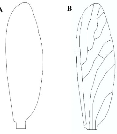
flying insects [2]. ... 11 Figure 2.1 Crane fly specimens. (A) Adult crane fly and (B) a sample of a crane fly forewing. ... 24 Figure 2.2 Typical micro-CT scan setup. A view or projection is acquired by directing the X-ray signal through a slice plane of the object and collecting the intensity measurements on the detector for a given object position. The process is repeated for multiple angular views of the object. ... 26 Figure 2.3 Reconstructed model from the micro-CT scan. (A) 3-D reconstructed model of the
crane fly forewing, (B) sliced-view of the reconstructed model at approximately a half its spanwise y-direction and (C) sample 2-D cross-sectional image [59]. ... 29 Figure 2.4 CAD model description of the crane fly forewing. CAD model for the (A) Membrane
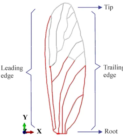
contour and (B) vein contour of the crane fly forewing... 31 Figure 2.5 Thick veins and thin veins sets for the crane fly forewing. Distribution of the thick
(red lines) and thin (gray lines) veins on the CAD model of the crane fly forewing... 32 Figure 2.6 Photomask required for the manufacturing of the insect-sized artificial wing. Dark
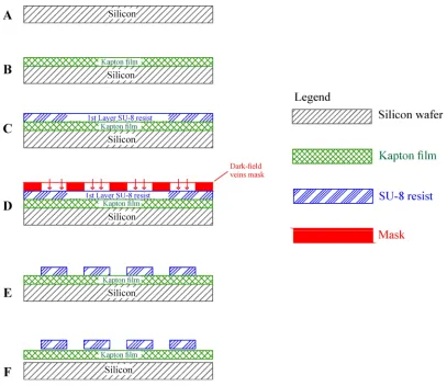
field photomask with (A) membrane pattern and (B) venation pattern required for the manufacturing of the artificial insect-sized wing. ... 38 Figure 2.7 Description of the photolithography process for the manufacturing of the
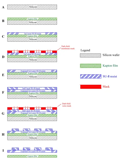
composite artificial insect-sized wing. (A) Conditioning and cleaning of the surface of the wafer, (B) attachment of the Kapton film to the wafer to biomimic the membrane of the insect, (C) spin coating of the layer of the photoresist SU-8 to pattern the venation network on the substrate, (D) alignment of the photomask of the venation network and exposure to UV light to the substrate, (E) development of the unexposed SU-8, and (F) final trimming of the composite artificial insect-sized wing. ... 42 Figure 2.8 Description of the photolithography process for the manufacturing of the single
xiii
Figure 2.9 DIC calibration targets. (A) The stereo-triangulation configuration requires calibration to locate the correct coordinate in space. (B) The bundle adjustment algorithm determines the shape of the calibration target by measuring the know distance between the coded markers; and thus, calculating the respective calibration parameters [82]. ... 54 Figure 2.10 Speckled surface patterns. (A, B, and C) Examples of inappropriate and (D, E, and
F) proper speckled patterns for the DIC technique [82]. ... 55 Figure 2.11 Subset tracking correlation. The DIC technique tracks the changes in gray-scale
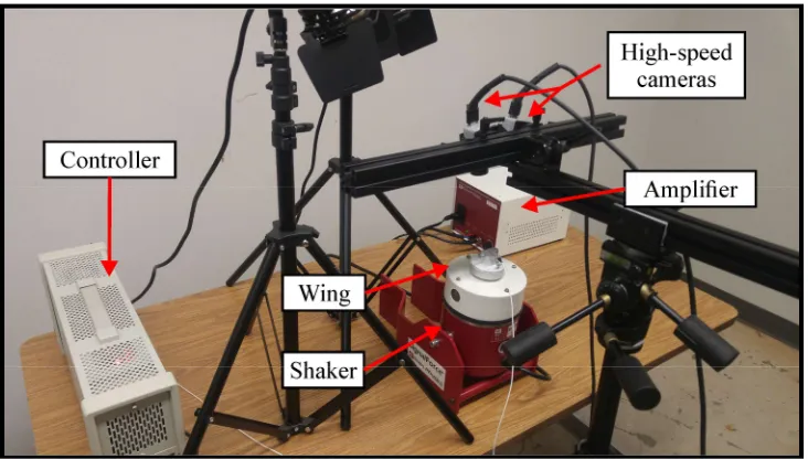
value pattern in small collections of neighboring pixels called subsets, represented by the red squares, during deformation [83]. ... 56 Figure 2.12 Description of the modal analysis experimental setup. Illustration showing the
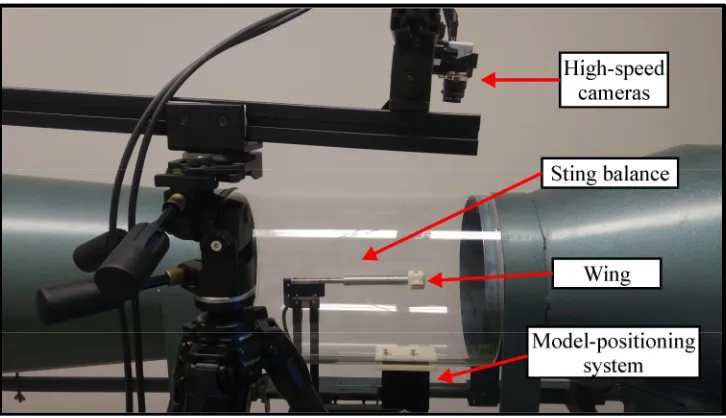
controller, the amplifier, the shaker, and the high-speed cameras from the DIC system to conduct the experimental modal analysis. ... 58 Figure 2.13 Description of the aerodynamics experimental setup. Illustration showing the sting
balance, the model-positioning system, and the high-speed cameras from the DIC system to conduct the aerodynamics experiments. ... 60 Figure 2.14 FE model description of the artificial insect-sized wing. (A) Membrane model, (B)
membrane mesh, (C) vein model, and (D) vein mesh of the artificial insect-sized wing. ... 61 Figure 2.15 Tolerance region around the membrane master surface. Description of the
tolerance region where the slave nodes of the B32 elements were tied to the master nodes of the S4R elements of the FE model of the crane fly forewing [68]. ... 63 Figure 2.16 Node-to-surface tie constraint representation. Description of the node-to-surface
approach implemented to interpolate quantities from the master nodes to the tie point [68]. ... 64 Figure 2.17 CFD model description of the artificial insect-sized wing. (A) CFD domain (B)
CFD mesh, (C) mesh refinement at the vicinity of the wing, and (D) mesh layers for capturing the viscous effects. ... 66 Figure 2.18 Boundary conditions surfaces of the CFD domain. Description of the different
faces of the CFD domain for the assignment of the boundary conditions. ... 68 Figure 2.19 Co-simulation interfaces descriptions for the artificial wing FSI model. (A) For
the FE model and (B) for the CFD model. ... 70 Figure 3.1 SIMPLE method algorithm. Description of the steps for the implementation of the
SIMPLE algorithm ... 76 Figure 4.1 Composite material artificial insect-sized wing sample. A zoomed-in view of a
sample of a composite artificial insect-sized wing. ... 81 Figure 4.2 Single material artificial insect-sized wing sample. A zoomed-in view of a sample
of a single material artificial insect-sized wing... 82 Figure 4.3 Wing sample prepared and mounted on shaker. The wing sample prepared with the
required speckle pattern and attached to the circular plate for the conduction of the vibration experiments. ... 84 Figure 4.4 Closed-loop feedback control system for the experimental modal analysis setup. The different components of the vibrational experimental setup were configured as a closed-loop feedback system to provide and monitor the correct excitation levels. .... 85 Figure 4.5 PSD profile of the random excitation signal. Plot of the PSD function showing the
xiv
Figure 4.6 Measurement points for the calculation of the FFT. The time-varying out-of-plane displacement data was extracted from random measurement points located along the surface of the artificial wing for the calculation of the FFT. ... 92 Figure 4.7 FFT of the displacement response of the Composite-1 artificial wing. On the left
column both the FFT averaged from the four runs with the respective smoothed FFT and on the right column only the smoothed FFT for the out-of-plane displacement response of (A) point P2, (B) point P3, (C) point P4, (D) point P5, (E) point P6, and (F) point P7 of the Composite-1 artificial wing. ... 95 Figure 4.8 FFT of the velocity response of the Composite-1 artificial wing. On the left column
both the FFT averaged from the four runs with the respective smoothed FFT and on the right column only the smoothed FFT for the velocity response of (A) point P2, (B) point P3, (C) point P4, (D) point P5, (E) point P6, and (F) point P7 of the Composite-1 artificial wing. ... 96 Figure 4.9 FFT of the displacement response of the Composite-2 artificial wing. On the left
column both the FFT averaged from the four runs with the respective smoothed FFT and on the right column only the smoothed FFT for the out-of-plane displacement response of (A) point P2, (B) point P3, (C) point P4, (D) point P5, (E) point P6, and (F) point P7 of the Composite-2 artificial wing. ... 97 Figure 4.10 FFT of the velocity response of the Composite-2 artificial wing. On the left column
both the FFT averaged from the four runs with the respective smoothed FFT and on the right column only the smoothed FFT for the velocity response of (A) point P2, (B) point P3, (C) point P4, (D) point P5, (E) point P6, and (F) point P7 of the Composite-2 artificial wing. ... 98 Figure 4.11 FFT of the displacement response of the Composite-3 artificial wing. On the left
column both the FFT averaged from the four runs with the respective smoothed FFT and on the right column only the smoothed FFT for the out-of-plane displacement response of (A) point P2, (B) point P3, (C) point P4, (D) point P5, (E) point P6, and (F) point P7 of the Composite-3 artificial wing. ... 99 Figure 4.12 FFT of the velocity response of the Composite-3 artificial wing. On the left column
both the FFT averaged from the four runs with the respective smoothed FFT and on the right column only the smoothed FFT for the velocity response of (A) point P2, (B) point P3, (C) point P4, (D) point P5, (E) point P6, and (F) point P7 of the Composite-3 artificial wing. ... 100 Figure 4.13 FFT of the displacement response of the Composite-4 artificial wing. On the left
column both the FFT averaged from the four runs with the respective smoothed FFT and on the right column only the smoothed FFT for the out-of-plane displacement response of (A) point P2, (B) point P3, (C) point P4, (D) point P5, (E) point P6, and (F) point P7 of the Composite-4 artificial wing. ... 101 Figure 4.14 FFT of the velocity response of the Composite-4 artificial wing. On the left column
both the FFT averaged from the four runs with the respective smoothed FFT and on the right column only the smoothed FFT for the velocity response of (A) point P2, (B) point P3, (C) point P4, (D) point P5, (E) point P6, and (F) point P7 of the Composite-4 artificial wing. ... 102 Figure 4.15 FFT of the displacement response of the Single-1 artificial wing. On the left
xv
response of (A) point P2, (B) point P3, (C) point P4, (D) point P5, (E) point P6, and (F) point P7 of the Single-1 artificial wing. ... 103 Figure 4.16 FFT of the velocity response of the Single-1 artificial wing. On the left column
both the FFT averaged from the four runs with the respective smoothed FFT and on the right column only the smoothed FFT for the velocity response of (A) point P2, (B) point P3, (C) point P4, (D) point P5, (E) point P6, and (F) point P7 of the Single-1 artificial wing. ... 104 Figure 4.17 FFT of the displacement response of the Single-2 artificial wing. On the left
column both the FFT averaged from the four runs with the respective smoothed FFT and on the right column only the smoothed FFT for the out-of-plane displacement response of (A) point P2, (B) point P3, (C) point P4, (D) point P5, (E) point P6, and (F) point P7 of the Single-2 artificial wing. ... 105 Figure 4.18 FFT of the velocity response of the Single-2 artificial wing. On the left column
both the FFT averaged from the four runs with the respective smoothed FFT and on the right column only the smoothed FFT for the velocity response of (A) point P2, (B) point P3, (C) point P4, (D) point P5, (E) point P6, and (F) point P7 of the Single-2 artificial wing. ... 106 Figure 4.19 FFT of the displacement response of the Single-3 artificial wing. On the left
column both the FFT averaged from the four runs with the respective smoothed FFT and on the right column only the smoothed FFT for the out-of-plane displacement response of (A) point P2, (B) point P3, (C) point P4, (D) point P5, (E) point P6, and (F) point P7 of the Single-3 artificial wing. ... 107 Figure 4.20 FFT of the velocity response of the Single-3 artificial wing. On the left column
both the FFT averaged from the four runs with the respective smoothed FFT and on the right column only the smoothed FFT for the velocity response of (A) point P2, (B) point P3, (C) point P4, (D) point P5, (E) point P6, and (F) point P7 of the Single-3 artificial wing. ... 108 Figure 4.21 FFT of the displacement response of the Single-4 artificial wing. On the left
column both the FFT averaged from the four runs with the respective smoothed FFT and on the right column only the smoothed FFT for the out-of-plane displacement response of (A) point P2, (B) point P3, (C) point P4, (D) point P5, (E) point P6, and (F) point P7 of the Single-4 artificial wing. ... 109 Figure 4.22 FFT of the velocity response of the Single-4 artificial wing. On the left column
both the FFT averaged from the four runs with the respective smoothed FFT and on the right column only the smoothed FFT for the velocity response of (A) point P2, (B) point P3, (C) point P4, (D) point P5, (E) point P6, and (F) point P7 of the Single-4 artificial wing. ... 110 Figure 4.23 Experimental mode shapes of the artificial insect-sized wing. (A) First (B) second,
and (C) third mode shape of the artificial insect-sized wing. ... 111 Figure 4.24 Wing sample prepared and fixed inside the wind tunnel. The wing sample
prepared with the required speckle pattern and fixed inside the wind tunnel using the custom-made socket for the conduction of the aerodynamic experiments. ... 113 Figure 4.25 Experimental structural aerodynamic response of the artificial insect-sized wing.
xvi
Figure 4.26 Mode shapes of the rectangular shell with one fixed end and three free ends. (A and B) First at 15.20 Hz, (C and D) second at 79.62 Hz, and (E and F) third at 94.87 Hz mode shapes of the rectangular flat shell. ... 118 Figure 4.27 Mode shapes of the elliptical membrane with a clamped edge. (A and B) First at
163.54 Hz, (C and D) second at 186.25 Hz, and (E and F) third at 210.20 Hz mode shapes of the elliptical membrane. ... 120 Figure 4.28 Mode shapes of the cantilever beam with tubular cross-section. (A) First at 171.11
Hz, (B) second at 1096.91 Hz, and (C) third at 3069.30 Hz mode shapes of the cantilever beam with tubular cross-section. ... 122 Figure 4.29 CFD validation. Comparison between the CFD model and the Blasius solution [103]
for the x-component of velocity profile along the trailing edge of the flat plate. ... 125 Figure 4.30 FSI validation. Comparison between the FSI model and the results from Glück [108]
for the oscillations at the tip of a flexible plate due to an applied pressure. ... 126 Figure 4.31 Mesh independence study for the FE model of the artificial insect-sized wing.
Variation of the natural frequencies of the composite material artificial wing with respect to mesh resolution of the FE model. ... 127 Figure 4.32 Mode shapes of the artificial insect-sized wing. (A and B) Front and side view of
first mode shape (C and D) front and side view of second mode shape, and (E and F) front and side view of third mode shape of the artificial insect-sized wing. ... 129 Figure 4.33 Location of the node A and central path along the spanwise y-direction. The node
A was defined to monitor the convergence of the FSI results. A central path along the spanwise y-direction of the artificial wing was defined for the analysis of the FSI results. ... 130 Figure 4.34 Mesh independence study for the FSI simulation. The variation of (A) the
deformation at node A, (B) the coefficient of drag, and (C) the coefficient of lift of the artificial wing with respect to a change of the number of nodes in the CFD mesh only was monitored for the mesh independence study. ... 131 Figure 4.35 Structural deformation response of the composite material artificial insect-sized
wing. Deformation and von Mises stress of the artificial insect-sized wing under steady airflow for (A and B) Re=29, (C and D) Re=150, and (E and F) Re=290 and 10 deg angle of attack; and (G) deformation magnitude along a central path in the spanwise y-direction under steady airflow for different Reynolds number. ... 135 Figure 4.36 Structural deformation response of the single material artificial insect-sized
wing. Deformation and von Mises stress of the artificial insect-sized wing under steady airflow for (A and B) Re=29, (C and D) Re=150, and (E and F) Re=290 and 10 deg angle of attack; and (G) deformation magnitude along a central path in the spanwise y-direction under steady airflow for different Reynolds number. ... 136 Figure 4.37 Aerodynamic performance of the artificial insect-sized wing. (A) Coefficient of
drag variation with respect to angle of attack and Reynolds number, (B) coefficient of lift variation with respect to angle of attack and Reynolds number, and (C) aerodynamic efficiency of the artificial insect-sized wing. ... 137 Figure 4.38 Velocity vectors for a Reynolds number of 29. Velocity vectors of the flow over
xvii
Figure 4.39Velocity vectors for a Reynolds number of 150. Velocity vectors of the flow over the artificial wing for (a) 0 deg, (b) 10 deg, (c) 15 deg, (d) 20 deg, (e) 25 deg, (f) 30 deg, and (g) 40 deg angles of attack for a Reynolds number of 150. ... 139 Figure 4.40 Velocity vectors for a Reynolds number of 290. Velocity vectors of the flow over
xviii
LIST OF TABLES
Table 1.1 MAVs design requirements as outlined by the Defense Advanced Research Projects
Agency (DARPA) [7, 8] ... 14
Table 2.1 Reported morphological and kinematic parameters of the crane fly ... 24
Table 2.2 Micro-CT scanning setup settings for the crane fly forewing ... 28
Table 2.3 Morphological parameters of the crane fly measured from the reconstructed micro-CT model ... 30
Table 2.4 Mechanical properties of the artificial materials and the crane fly forewing ... 34
Table 2.5 Fluid properties of the CFD model ... 65
Table 2.6 Boundary conditions of the CFD model ... 68
Table 4.1 Measured morphological parameters from the composite material artificial insect-sized wing ... 80
Table 4.2 Measured morphological parameters from the single material artificial insect-sized wing ... 82
Table 4.3 DIC acquisition settings for the conduction of the vibration experiments ... 88
Table 4.4 Random excitation signal parameters ... 89
Table 4.5 Breakpoint table for the PSD function of the random excitation signal ... 90
Table 4.6 Experimental natural frequencies for the composite material wing ... 94
Table 4.7 Experimental natural frequencies for the single material wing ... 94
Table 4.8 DIC acquisition settings for the conduction of the aerodynamic experiments ... 114
Table 4.9 Comparison between the natural frequencies of the FE model of the rectangular shell and the analytical solution [93] ... 118
Table 4.10 Comparison between the natural frequencies of the FE model of the elliptical membrane and the analytical solution [106] ... 120
Table 4.11 Comparison between the natural frequencies of the FE model of cantilever beam with tubular cross-section and the analytical solution [6] ... 122
Table 4.12 Comparison between the boundary layer of the CFD model solution and the Blasius solution ... 125
xix
ABSTRACT
The exceptional flying characteristics of airborne insects motivates the design of
biomimetic wing structures that can exhibit a similar structural dynamic behavior. For this
purpose, this investigation describes a method for both manufacturing a biomimetic insect-sized
wing using the photolithography technique and analyzing its structural dynamic response. The
geometry of a crane fly forewing (family Tipulidae) is acquired using a micro-computed
tomography scanner. A computer-aided design model is generated from the measurements of the
reconstructed scanned model of the insect wing to design the photomasks of the membrane and
the venation network required for the photolithography procedure. A composite material wing is
manufactured by patterning the venation network using photoresist SU-8 on a Kapton film for
the assembling of the wing. A single material artificial wing is fabricated using the photoresist
SU-8 for both the membrane and the network of veins. Experiments are conducted using a modal
shaker and a digital image correlation (DIC) system to determine the natural frequencies and the
mode shapes of the artificial wing from the fast Fourier transform of the displacement response
of the wing. The experimental results are compared with those from a finite element (FE) model
of the wing. A numerical simulation of the fluid-structure interaction is conducted by coupling
the FE model of the artificial wing with a computational fluid dynamics model of the
surrounding airflow. From these simulations, the deformation response and the coefficients of
drag and lift of the artificial wing are predicted for different freestream velocities and angles of
attack. Wind-tunnel experiments are conducted using the DIC system to determine the structural
deformation response of the artificial wing under different freestream velocities and angles of
attack. The vibration modes are dominated by a bending and torsional deformation response. The
xx
of the wing with Reynolds number. The aerodynamic performance, defined as the ratio of the
coefficient of lift to the coefficient of drag, of the artificial wing increases with Reynolds number
and angle of attack up to the critical angle of attack.
Keywords: Biomimetic artificial insect-sized wing, vibrations, aerodynamics, MAVs,
1
CHAPTER 1
INTRODUCTION
The research on the field of aerodynamics has always been concerned on optimizing the
structural dynamic response of airborne engineering systems. It is of special interest to
implement design strategies that could maximize the aerodynamic efficiency of aerial vehicles,
meaning increasing the lift production while minimizing the drag; and that could offer adequate
bending and torsional resistance to aerodynamic and inertial loadings. Through flying insects,
nature provides exceptional examples of biomechanical aerial assemblies with an outstanding
structural dynamic performance. These organisms have developed incomparable flight skills
thanks to the compliant reaction of their wings to the moving fluid. Researchers have turned their
attention to this behavior and efforts are currently allocated to the design of biologically inspired
insect-sized wing structures capable of successfully emulating the structural dynamic response of
their nature analogs for their possible implementation into the new generation of biologically
inspired micro air vehicles (MAVs). Detailed descriptions and analysis of the modal and the
aerodynamics characteristics of both the insect and the artificial wings are required for
biomimicking optimal flight and maneuver conditions similar to those encounter during insect
flight.
1.1
Motivation and Objectives of the Study
MAVs are miniature-scaled autonomous aircrafts used for military and civilian
operations at hazardous or inaccessible environments where human presence is to be avoided.
Examples of the tasks performed by MAVs include field reconnaissance, surveillance, and
weather conditions monitoring. The success in performing these duties is strongly dependent on
2
for MAVs that meet the aforesaid characteristics has motivated the study and development of
different design approaches for these aircrafts, one of them being the biologically inspired
method which attempts to biomimic the excellent maneuver skills during low-speed flight and
hovering mastered by insects. These nature-inspired MAVs offer several advantages with respect
to their multirotor or fixed wing analogs, such as higher lift-to-drag ratios, lower power
consumption, and smaller size systems.
The optimized design of a flexible wing structure is a critical element of a biologically
inspired MAV. The research on the field of aerodynamics of insect flight advocates that the
unique aerodynamic skills of aerial insects is strongly dependent on the presence of relatively
flexible wings. The motivation of this study is the development of an artificial biologically
inspired insect-sized wing capable of biomimicking the pliant structural dynamic behavior of its
nature analog for the consequent implementation into a nature inspired insect-sized MAV. For
this purpose, this investigation details at first a method for characterizing and analyzing the
morphology and the structural behavior of a crane fly forewing to determine key design aspects
that must be transferred to the artificial wing structure. A procedure is then detailed for
manufacturing an artificial insect-sized wing of similar morphology and for investigating its
structural dynamic response in terms of the modal characteristics, the time-varying deformation
due to aerodynamic loading, and the aerodynamic coefficients. The outcomes of this
investigation can be evaluated from the following objectives and sub-objectives.
1.1.1
Overall Objective
1) To develop a method for designing and analyzing a biologically inspired insect-sized
3
1.1.2
Sub-Objectives
1) To characterize the internal and the external morphologies of an insect wing.
2) To develop a computer-aided design (CAD) model of the insect wing.
3) To manufacture a biologically inspired insect-sized wing that mimics the
morphology, mechanical properties, and structural dynamic performance from its
nature counterpart.
4) To estimate the modal characteristics of the artificial biologically inspired
insect-sized wing using a vibrational experimental setup.
5) To determine the structural dynamic response of the artificial biologically inspired
insect-sized wing in a low-speed wind tunnel with airflow conditions that are
representative of the flight regime of MAVs.
6) To develop a finite element (FE) model of the artificial wing to determine its modal
characteristics.
7) To develop a structure-aerodynamic interaction model to investigate the structural
dynamic response of the artificial biologically inspired insect-sized wing under
different airflow conditions that are representative of the flight regime of MAVs.
8) To develop a FE model of the insect wing to determine its modal characteristics.
9) To develop a structure-aerodynamic interaction model to investigate the structural
dynamic response of the insect wing under different airflow conditions that are
representative of the flight regime of such insect.
10)To validate the structure-aerodynamic interaction models of the artificial biologically
inspired insect-sized wing with the data acquired from the vibration and wind-tunnel
4
1.2
Background Theory
1.2.1
Aerodynamic Forces on an Object Immersed in a Fluid
The identification of general aerodynamic terminology associated to any object immersed
in a fluid is required before proceeding with further discussion. The geometry of a body of any
size and shape—namely a cylinder, a flat plate, or an insect wing for instance—immersed on a
fluid consists of the leading or foremost edge which interacts with the flow streamlines at first
and the trailing or rear edge where the flow streamlines leave the surface of the body. The chord
length c is defined as the linear distance between the trailing edge and the leading edge. The
freestream velocity V∞is defined as the flow velocity far ahead of the body. The angle of attack α
is defined as the angle between the chord and the freestream velocity. These aerodynamic terms
are exemplified in Fig. 1.1.
Moments and forces are generated at the fluid-body interface when a fluid moves over an
immersed body. The generation of these forces and moments is directly related to the pressure
and shear stress distributions along the surface area of the immersed body [1]. The pressure or
normal stress acts normal to the surface of the body; whereas the shear stress acts tangential to
the surface. The net effect of the pressure and shear distributions integrated over the complete
body surface is a resultant aerodynamic force R and a moment M on the body, both of them are
5
Figure 1.1 Aerodynamic definitions. Resultant aerodynamic force and moment exerted on a body immersed on a fluid [1].
The resultant aerodynamic force R can be split into an infinite number of components
depending on which reference frame is employed. Commonly used reference frames are the
freestream velocity and the chord length.
When the freestream velocity is used as the reference frame, the resultant aerodynamic
force R can be divided into the lift force FL and the drag force FD as shown in Fig. 1.2. The lift
force FL is defined as the component of the resultant aerodynamic force R perpendicular to the
freestream velocity. The drag force FD is the component of the resultant aerodynamic force R
parallel to the freestream velocity.
When the chord length is used as the reference frame, the resultant aerodynamic force R
can be divided into the normal force FN and the axial force FA components as shown in Fig. 1.2.
The normal force FN is the component of the resultant aerodynamic force R perpendicular to the
chord. The axial force FA is the component of the resultant aerodynamic force R parallel to the
6
Figure 1.2 Aerodynamic force components. Description of the drag, lift, axial, and normal force components exerted on a body immersed on a fluid [1].
The generation of drag and lift determines the aerodynamic efficiency of a particular
body; therefore, they are discussed in detail in the following paragraphs. The mathematical
formulation to determine the drag and the lift forces exerted on a surface must take into account
the pressure P and shear stress τ distributions. A basic trigonometric analysis on Fig 1.2 yields
the relation for the drag force and the lift force in terms of the axial and normal force
components. These mathematical relations are presented in Eqs. 1.1. and 1.2 [1].
sin
cos
D N A
F
F
F
(1.1)cos
sin
L N A
F
F
F
(1.2)The integrations of the pressure P (stress component normal to the surface and oriented at
an angle θ relative to the perpendicular) and the shear stress τ (stress component tangential to the
surface and oriented at the same angle θ relative to the horizontal) distributions over the surfaces
of a differential element ds, shown in Fig. 1.3, are required to determine an expression for the
7
presented in [1]. The final equations for calculating the total axial force F′A and the total normal
force F′N per unit span are shown in Eqs. 1.3 and 1.4, respectively [1].
Figure 1.3 Force analysis acting on a differential element. Nomenclature for the integration of the pressure p and the shear stress τ distributions over the surfaces of a differential element ds [1].
sin cos
sin cos
TE TE
A upper upper upper lower lower lower
LE LE
F
P
ds
P
ds (1.3)
cos sin
cos sin
TE TE
N upper upper upper lower lower lower
LE LE
F
P
ds
P
ds (1.4)Substituting Eqs. 1.3 and 1.4 into Eqs. 1.1 and 1.2 allows the calculation of the respective
total drag and total lift forces per unit span of the object. Alternatively, the drag and lift forces
can be defined in terms of dimensionless parameters called the coefficient of drag CD and the
coefficient of lift CL which are defined in general terms in Eqs. 1.5 and 1.6, respectively [1].
2
2 D D
F C
V S
8 2 2 L L F C V S
(1.6)
where FD is the drag force, FL is the lift force, ρ∞ represents the density of the fluid, V∞is the
freestream velocity, and S is the reference area of the body.
1.2.2
Viscous and Inviscid Flow Concepts: Drag and Lift Generation
For most problems in aerodynamics, the shear stress has a meaningful effect on the flow
region where the velocity gradients are substantial. For the vast region of the flow field away
from the body, the velocity gradients are relatively small and friction plays virtually no role;
therefore, the flow is considered to be inviscid. However, for the thin region of the flow adjacent
to the surface, the velocity gradients are large and friction due to the viscosity plays a defining
role. This thin viscous region adjacent to the surface of the body is called the boundary layer and
it increases in the direction of the flow [1]. The boundary layer is extremely important in
aerodynamics as far as to determine how much influence it has in the generation of the
aerodynamic forces.
At this point, it is convenient to introduce the definition of the Reynolds number—a
dimensionless quantity that represents the ratio of the inertial forces to the viscous forces. The
Reynolds number governs the nature of viscous flows. Mathematically, the Reynolds number Re
is defined in Eq. 1.7,
Re
V L
(1.7)where ρ∞ represents the density of the fluid, V∞is the freestream velocity, L is the characteristic
9
Recalling Figs. 1.2 and 1.3, the pressure force P acts normal to the surface, which in
general for the aerodynamic bodies is the same as the vertical direction, that is, the lift direction.
Contrarily, the shear stress τ acts tangential to the surface, which is mainly the horizontal or drag
direction. Therefore, it can be concluded that the generation of lift is mainly influenced by the
pressure and it can be estimated from inviscid flow theory. On the other hand, the generation of
drag can have two sources. At low Reynolds numbers, the viscous effects are predominant with
significant amount of skin-friction drag; while at large Reynolds number, the inertial forces have
more influence and pressure drag effects due to flow separation may exist.
1.2.3
Insect Flight Aerodynamics
The characterization of the aerodynamics of insect flight has been a challenging task. The
small scale of insects and the high frequency flapping motion of their wings make experimental
analysis difficult. Nevertheless, the development of different computational tools such as the
computational fluid dynamics (CFD), together with the progression of advanced experimental
setups such as high-speed cameras, digital image correlation software, and particle image
velocimetry systems have made possible the analysis of the structural behavior of insect wings
under aerodynamic loading and the flow characterization related to insect flight.
The geometry of a typical insect wing consists of the leading edge and the trailing or rear
edge. Correlated to airfoil terminology, the wing span of an insect wing is referred as the linear
distance from the tip of the wing to the root of the wing where it intersects with the thorax of the
insect; the wing span is also known as the longitudinal axis of the wing. On the other hand, the
chord length is defined as the linear distance between the trailing edge and the corresponding
10
Figure 1.4 Insect wing terminology. Identification of the main parts of an insect wing related to aerodynamics.
The aerodynamic flapping cycle of insects entails more than the simple translation of the
insect wing. The flapping cycle of an insect, shown in Fig. 1.5, consists of the downstroke and
the upstroke, which refer to the translation of the insect wing over the air to a lower or higher
angle of attack, respectively. The flapping cycle also consists of two transitional stages that
involve the rotation about the longitudinal axis of the wing. These stages are known as the
pronation and the supination. Wing pronation takes place during the transition from upstroke to
downstroke and it consists in the inward rolling of the wing towards the thorax of the insect so
that the leading edge faces downwards. Contrarily, wing supination occurs during the transition
from downstroke to upstroke and it involves the outward rolling of the wing towards the torso of
11
Figure 1.5 Flapping cycle of insects. Description of the different stages of the flapping cycle for flying insects [2].
Flying insects generate the necessary lift and thrust by passively experiencing elastic
deformations in their compliant wings coupled to unsteady aerodynamic mechanisms derived
from the structural response of the insect wing to aerodynamic and inertial loadings. These
passive deformations may include twisting of the wings to change the angle of attack during the
stroke cycle and altering the camber from the leading edge of the wing to the tip of the wing [2].
Different unsteady mechanisms that improve the aerodynamic performance of insects have been
identified. The first mechanism is the clap and fling. At the end of the upstroke, the leading edge
of each wing touches each other or “clap” before the trailing edge makes contact, progressively
closing the gap between them and creating a shape similar to a vertical plate. As the wing presses
together closely, the opposing circulations of the fluid from each of the wings are cancelled out
each other. Following, at the beginning of the downstroke, the wings are quickly pronated with
the leading edge “flinging” apart, creating a low-pressure region between them that causes the
gap to be filled with entering air, consequently providing an initial momentum and a vortex of air
12
The second well-known unsteady aerodynamic mechanism in insect flight is the delayed
stall. As the wing increases its angle of attack, the fluid stream going over the wing separates as
it crosses the leading edge of the wing but reattaches before it reaches the trailing edge of the
wing. In such case, the leading edge vortex occupies the separation zone above the wing and a
greater downward momentum is imparted to the fluid, therefore, increasing the lift magnitude
[2–4]. As the wing translates at a higher angle of attack, the leading edge vortex grows in size
until flow reattachment is no longer possible and the lift dramatically decreases. This
phenomenon is known as stall. The possibility of flow reattachment provided by the compliant
deformation of the insect wing allows the delay of the stall condition.
The third unsteady aerodynamic mechanism is known as the wake capture and rotational
circulation. This mechanism has a coupled effect in which the insect wing takes advantage of the
wake created by the previous stroke. The wake allows an upward lift to be generated when the
wing’s own rotation creates air circulation at the end of the stroke [2]. The wake capture and
rotational circulation mechanism starts as the wing reverses stroke and it sheds a vortex at both
the leading and trailing edges. These shed vortices induce a strong velocity field. As the wing
reverse direction, it encounters the enhanced velocity field which increases the magnitude of the
aerodynamic forces immediately following the stroke reversal [2, 3].
1.2.4
Vibrations: Natural Frequency, Mode Shapes, and Resonance
Vibration, also commonly referred as oscillation, is a motion that repeats itself after an
interval of time [5]. Vibrational loads are inherent to aerial insects and biologically inspired
MAVs due to their flapping flying cycle. These repetitive loads cause fatigue that can eventually
lead to failure or degrade the performance of the structure. For this reason, a characterization of
13
assembly. In general, the modal characterization involves the calculation of the natural
frequencies and the identification of the respective mode shapes of a particular structure.
The concept of frequency of vibration of any mechanical system or structure is one of the
most important concepts in vibration analysis. If a system, after an initial disturbance, is left to
vibrate on its own, the frequency or number of cycles per unit time at which it oscillates without
external forces is known as the natural frequency [5]. The mode shape is a mathematical
description of the deflection of the oscillations. It forms a pattern that describes the shape of
vibration if the system is left to vibrate only at the corresponding natural frequency [6].
Identifying the natural frequency of a system is of importance to avoid failure due to resonance.
Whenever the natural frequency of vibration of a structure matches with the frequency of
external excitation, the amplitude of the oscillations increases substantially; this phenomenon is
known as the resonance and may lead to significant structural damage or failure due to excessive
deflections.
For the purpose of the modal analysis of this investigation, the artificial wing must be
considered as a multiple-degree-of-freedom system where its mass and its stiffness is distributed
throughout its structure as a series of infinitely small elements. Hence, the wing is called a
distributed-parameter system in which each of these infinite number of elements will move
relative to each other in a continuous fashion when vibrating. Given the infinite degrees of
freedom, the artificial wing will have an infinite number of natural frequencies [6]. The concept
of resonance in an infinite degree-of-freedom system is based on the idea that a harmonic driving
force excites the system at its natural frequency and causes an unbounded oscillation in the
undamped case and a response with a maximum amplitude in the damped case [6]. The objective
14
reinforcement from repetitive loads and to determine the resonance frequencies which may lead
to oscillations of large amplitude. In general, for any structure, the first three natural frequencies
dominate the vibration response—meaning their estimation and analysis is fundamental and
necessary for the design of the structure.
1.2.5
Micro Air Vehicles
MAVs are autonomous, lightweight, small-scale flying devices with a maximum wing
span of 15 cm and a maximum flying speed of approximately 15 m/s as detailed in Table 1.1. An
interest in the design of these aerial devices has immensely grown over the last years due to their
potential to operate in remote or otherwise hazardous locations where they may perform a variety
of tasks, including but not limited to, reconnaissance, surveillance, and safety inspection. To
accomplish these tasks, the wings of MAVs should be aerodynamically efficient, optimized
structures; such as the wings found in different insects. The design of biologically inspired
insect-sized wings aims to mimic the superlative maneuverability characteristics during
low-speed flight mastered by insects for their implementation into the new generation of nature
inspired MAVs.
Table 1.1 MAVs design requirements as outlined by the Defense Advanced Research Projects Agency (DARPA) [7, 8]
Specifications Requirements Details
Size <15.24 cm Maximum dimension
Weight ~100 g Objective gross takeoff weight (GTOW)
Range 1 to 10 km Operational range
Endurance 60 min Loiter time on station
Altitude <150 m Operational ceiling
Speed 15 m/s Maximum flight speed
Payload 20 g Mission dependent
15
1.3
Literature Survey
1.3.1
Insect Wing Aerodynamics and Structural Behavior
The insect wings experience highly elastic deformations during flapping flight to be able
to generate more upward than downward force. The compliant wing deformation achieves this
purpose in different ways. For instance, the insect wing may twist to change the angle of attack
throughout the stroke and create an asymmetric force generation; similarly, the camber of the
wing may be altered to increase or decrease the area of the wing exposed to the aerodynamic
forces [9]. Further evidence supported that the development of aerodynamic unsteady
mechanisms coupled to the elastic distortion of the wing allowed insects to proficiently hover
and maneuver in different airflow conditions [2, 10]. Miller and Peskin [4, 11] analyzed in detail
the clap and fling mechanism and concluded that its lift-enhancing effects were greater for low
Reynolds numbers. It was further confirmed that large lift forces were not only generated during
the rotation of the wing but they were also transiently enhanced during the translation of the
wing following the fling. Their results highlighted that the flexibility of the wing reduced the
large drag forces generated during the clap and fling while maintaining lift for a certain range of
wing flexibilities. Santhanakrishnan et al. [12] assessed the role of bristled wing structures to
reduce the drag required to clap together and fling apart wings at lower Reynolds number. Their
study showed that the porous nature of the wing contributed largely to the reduction of drag. The
existence of the leading edge vortex related to the delayed stall aerodynamic mechanism and its
contribution to the production of aerodynamic forces were addressed by Ellington et al. [13],
Birch et al. [14] and Harbig et al. [15]. Their research demonstrated that the resulting high lift
forces were influenced by the presence of a leading edge vortex which remained attached to the
16
above the wing that enhanced the generation of lift. The wake capture and rotational circulation
unsteady mechanism was studied by Wang [16] to determine how the lift was affected by the
enhanced velocity field generated during the flapping cycle. They concluded that flow
circulation was induced as the trailing edge vortex was shed from the wing and dissipated into
the wake to increase the velocity of the fluid relative to the wing. The enhanced velocity field
exerted an additional upward momentum to the wing.
Further experimental characterizations of the structural dynamic behavior of insect wings
were conducted. Rees [17] concluded that the corrugation of the wing could offer a reduction
both in deflection and in the maximum stress experienced for a given loading. Ennos and
Wootton [18] and Wootton [19, 20] determined experimentally that the bending and twisting of
insect wings were highly dependent on their structure and venation morphology and that these
altered the directions and magnitudes of the aerodynamic forces. Combes and Daniel [21, 22]
studied the relationship between the venation pattern and wing flexibility and concluded that the
veins were responsible for a spanwise-chordwise anisotropy flexural stiffness distribution which
passively controlled the wing shape during flight. Zhao et al. [23] studied the impact of the
elasticity of the insect wing on its aerodynamic efficiency and showed that the aerodynamic
forces could be controlled by altering the trailing edge flexibility of the flapping wing. More
recently, Mountcastle and Combes [24] underlined the importance of the wing flexibility in the
hovering of a bumblebee, while Kang and Shyy [25] carried out simulations concerning insects
of small size for low values of the Reynolds number showing that the deformability played a
crucial role in the lift generation, enhancing the performance. In addition, Xiao et al. [26]
highlighted the effect of torsional stiffness and inertia on the dynamics of low aspect ratio
17
1.3.2
Numerical Studies on Insect Wing Aerodynamics and Structural Behavior
The FE method proved to be a high-fidelity technique for studies regarding the structural
response of insect wings. Wang et al. [27] and Li and Wang [28] studied the microstructures of
wing veins and analyzed the effects on the mechanical behavior of the veins based on tensile and
bending loading by the FE analysis. They observed that the veins of insects had a sandwich
microstructure which could withstand a greater torsional deformation with minimal mass.
Jongerius and Lentink [29] developed a FE model to determine the natural frequencies and the
deformation response of a dragonfly wing subjected to analytical estimates of aerodynamic and
inertial loads. Sims et al. [30] created a FE model of a hawk moth for the calculation of the
modal characteristics.
Different studies have been developed to analyze the two-dimensional (2-D) and
three-dimensional (3-D) fluid-structure interaction (FSI) of the insect wings and how it affects their
structural dynamic behavior. Ishihara et al. [31] studied the 2-D FSI in Dipterian flapping flight
and determined the cause of wing pitch changes. Yin and Luo [32] simulated the 2-D FSI in
hovering flight to investigate the effect of inertia and fluid deformation on hovering
performance. Young et al. [33] analyzed the aerodynamic consequences of wing deformation in
the desert locust using a 3-D CFD simulation based on detailed wing kinematics. Their results
showed that the time-varying wing twist and camber were essential to the maintenance of
attached flow and the consequent reduction of the associated loss of energy dissipated into the
wake; therefore, resulting in an overall increase of the aerodynamic efficiency. Dai et al. [34]
modeled the 3-D FSI of an elastic rectangular wing at a low aspect ratio during hovering flight
and showed that the chordwise deformation of the wing caused a passive dynamic pitching in
18
Complex numerical analysis with hybrid FSI formulations were conducted. These
formulations often dealt with adaptive or moving meshes to investigate the aerodynamics of
insect flight. The immersed boundary method (IBM) was among the accurate techniques for
predicting insect flight aerodynamics [35, 36]. In particular, De Rosis et al. [36] considered a
numerical approach that coupled the lattice Boltzmann method as the fluid solver and the
Galerkin FE method as the structural solver to investigate the behavior of 2-D symmetric
flapping wings moving in a viscous fluid. Su et al. [37] developed an unstructured mesh
incompressible flow solver based on arbitrary Lagrangian-Eulerian (ALE) method to investigate
the lift generation mechanisms of wings in hovering motions, including the wake capture, the
delayed stall, the rapid pitch, as well as the clap and fling.
1.3.3
Manufacturing and Characterization of Artificial Insect-Sized Wings
The understanding of the structural response of the insect wing to aerodynamic loading
has allowed the identification and development of suitable methods to manufacture insect-sized
wings for biologically inspired MAVs. The research on the field of aerodynamics of insect flight
advocates that the excellent maneuver skills during hovering and low-speed flight exhibited by
aerial insects is strongly dependent on the presence of relatively flexible wings. The
manufacturing of artificial wings for biologically inspired MAVs must not only attempt to
replicate the aesthetics of the nature analogs but also to biomimic its morphology and flexibility
in order to be able to emulate the structural dynamic performance of flying insects.
Different approaches have been considered to fabricate both single material and
composite material insect-sized wings. For this purpose, micromolding, photolithography, and
soft-lithography have been the most employed microfabrication techniques differing mainly on
19
Pornsin-sirirak et al. [38] manufactured a composite wing structure by patterning a
titanium-alloy metal onto a substrate to create the wing frame and attaching a Parylene-C film to
act as the wing membrane. A flapping mechanism was designed to test both cicada and artificial
insect-sized wings inside a wind-tunnel. Results suggested that the cicada wings had higher lift
coefficients than the artificial wings possibly explained by the higher compliance of the natural
wing.
The technique of soft-lithography was implemented by Tanaka et al. [39] to fabricate
flexible polydimethylsiloxane (PDMS) molds with the shape and dimensions of an insect wing.
These micromolds were used to cast a low-viscosity thermosetting polyurethane resin to create
the structural veins and attach a Parylene-C film as the membrane. As an expansion of the
previous approach, Tanaka et al. [40] studied the relationship between the stiffness distribution
in the wing and the flight performance by fabricating three different types of wing and evaluating
their performance in the free flight of an ornithopter. The wing that had a nonuniform stiffness
distribution along the span provided the best result in terms of the aerodynamic force per unit
weight and overall aerodynamic coefficients. Tanaka and Wood [41] developed corrugated
artificial insect wings by micromolding a thermosetting resin using laser machined molds. Both
techniques [39] [41] allowed the manufacturing of a single material wing structure.
Shang et al. [42] fabricated planar artificial insect-sized wings of diverse morphology
through a versatile manufacturing process that combined smart composite microstructures with
soft lithography. Insect-sized wings made of carbon fiber and a polyimide film for the biomimic
of the veins and the membrane, respectively, were manufactured. Measurements of the spanwise
20
length. Their methodology was implement into the successful project of the Harvard
Microrobotic Fly Robobee [43].
Xie et al. [44] fabricated a wing skeleton from carbon fibers cured inside a
micromachined aluminum mold; hold together by a Capran film. Measurements of the
time-averaged aerodynamic forces produced by the flapping wings in vacuum were conducted using a
force and torque sensor. The deformation of the artificial flapping wing was measured using a
digital image correlation (DIC) system. Results showed that the passive deformation of the wing
was fundamental to create thrust.
Bao et al. [45] developed a composite artificial insect wing with a membrane made of
PDMS and reinforced by SU-8 veins. Tests were conducted to measure the spanwise and
chordwise flexural stiffness of the artificial wing.
1.3.4
Experimental Studies on Biologically Inspired Artificial Wings
Further research efforts were done in smart materials that could potentially biomimic the
structural characteristics of insect wings. Different experimental setups were utilized for the
measurement of the full-field deformation due to aerodynamic loading and the calculation of the
aerodynamic coefficients of biologically inspired artificial wings.
Albertani et al. [46] documented both the elastic deformations using the DIC technique
and the corresponding aerodynamic forces using a sting balance of a flexible wing made of a
carbon fiber skeleton and a thin extensible rubber membrane.
Chakravarty [47] investigated the vibration characteristics of biologically inspired wings
fabricated from composite polyester materials. The effect of added mass, aerodynamic pressure,
21
proportional relationship was found between the magnitude of the natural frequency and the
added mass. Moreover, Chakravarty and Albertani [48] investigated the effects of aerodynamic
loads on the modal characteristics on a biologically inspired wing fabricated from a hyperleastic
membrane. It was determined that the natural frequency of a membrane increased with prestrain
level and that the damping of air had minimal effect on the natural frequencies of the wing but
assisted on reducing the out-of-plane modal amplitude of vibration.
Wu et al. [49] studied the structural properties of hummingbird-shaped membrane wings
fabricated from unidirectional carbon fibers and Capran by measuring the full-field deformation
of the wing using a DIC system and characterizing the surrounding airflow using the stereo
digital particle image velocimetry system at atmospheric pressure and in vacuum. The aeroelastic
behavior of the artificial wings was described and the relationship between flexibility and thrust
production was visually explained. Their research supported that wing deformation was a vital
feature for generating aerodynamic thrust in insects.
The DIC technique has been employed for the estimation of the pressure distribution on
the surface of artificial wings and the consequent prediction of the aerodynamic forces.
Carpenter and Albertani [50] measured the elastic deformations and strains of a pliant membrane
under aerodynamic loading using the DIC. The strain measurements were used to form virtual
strain sensors which served as the sensory input to the estimation of the normal pressure
distribution. Estimated pressure distributions were compared with a high-fidelity 3-D CFD. The
coefficients of liftand pitching moment for steady state flow conditions were estimated and
22
Banks et al. [51] developed a DIC based methodology that accurately captured the
passive deformation of a foil wing structure under a fluid loading condition. The coupled
deflection and blade twist for a range of wind speeds and angles of attack were evaluated. Steady
deformations at low angles of attack were shown to be well-captured; however, unsteady
deformations at higher angles of attack were observed as an increase in variability due to
hardware limitations in the current DIC system.
Alioli et al. [52] conducted a membrane shape and load reconstruction from DIC
measurements using the inverse FE analysis. They used DIC measurements to generate virtual
strain sensors on the surface of the membrane. Measurement were further manipulated to remap
the measured displacements and strains as needed to apply the inverse solution meshing of the
FE method.
1.4
Concluding Paragraph
Nature provides multiple examples of biomechanical systems that operate efficiently.
Researchers seek on them the inspiration to develop new concepts for their implementation in
engineered systems that could potentially offer a better performance than traditional ones. The
research on the field of aerodynamics of insect flight advocates that the excellent maneuver skills
during hovering and low-speed flight mastered by aerial insects is strongly dependent on the
presence of relatively flexible wings. Furthermore, the structure of an insect wing is evolutionary
determined by the need to optimize the production of favorable aerodynamic forces during flight.
Thus, to potentially emulate the structural dynamic performance of aerial insects, the
manufacturing of artificial wings for biologically inspired MAVs must not only attempt to
![Figure 1.3 Force analysis acting on a differential element. Nomenclature for the integration of the pressure p and the shear stress τ distributions over the surfaces of a differential element ds [1]](https://thumb-us.123doks.com/thumbv2/123dok_us/8922269.1842703/28.612.159.453.153.379/analysis-differential-nomenclature-integration-pressure-distributions-surfaces-differential.webp)
![Figure 2.3 Reconstructed model from the micro-CT scan. (A) 3-D reconstructed model of the crane fly forewing, (B) sliced-view of the reconstructed model at approximately a half its spanwise y-direction and (C) sample 2-D cross-sectional image [59]](https://thumb-us.123doks.com/thumbv2/123dok_us/8922269.1842703/50.612.121.496.71.287/reconstructed-reconstructed-forewing-reconstructed-approximately-spanwise-direction-sectional.webp)

![Figure 2.10 Speckled surface patterns. (A, B, and C) Examples of inappropriate and (D, E, and F) proper speckled patterns for the DIC technique [82]](https://thumb-us.123doks.com/thumbv2/123dok_us/8922269.1842703/76.612.89.520.314.557/figure-speckled-patterns-examples-inappropriate-speckled-patterns-technique.webp)