NUMERICAL MODELING AND EXPERIMENTAL
STUDY OF PROBE-FED RECTANGULAR DIELECTRIC
RESONATOR ANTENNA (RDRA) SUPPORTED BY FINITE
CIRCULAR GROUND PLANE
M. H. Neshati
Department of Electrical., Sistan & Baluchistan University Zahedan, 98164, Iran, [email protected]
Z. Wu
Department of Electrical & Electronics Engineering, UMIST Manchester M60 1QD, UK, [email protected]
(Received: April 3, 2004 – Accepted in Revised Form: June 10, 2004)
Abstract Dielectric Resonator Antennas (DRAs) have received increased interest in recent years for their potential applications in microwave and millimetre wave communication systems. DRAs are normally used with the support of a ground plane. The radiation and impedance properties therefore depend not only on their physical dimensions and dielectric properties, but also on the size of the ground plane. In this paper a probe-fed Rectangular Dielectric Resonator Antenna (RDRA) with dielectric constant εr=38 located on top of a ground plane operating at TE111 mode is investigated numerically and experimentally. The antenna is numerically simulated using the High Frequency Structure Simulator (HFSS) based on the Finite Element Method (FEM). The effect of the finite size of a circular ground plane on the radiation performance of the antenna including resonance frequency, radiation patterns, impedance bandwidth, quality factor and directivity of the RDRA is studied. The experimental results are also presented for various ground plane sizes and compared with those obtained by simulation. It is shown that the size of ground plane and considering an air gap in antenna structure could significantly affect the radiation and impedance properties of a DRA. They should be considered in the design of the antenna for practical applications.
Key Words Dielectric Resonator, Conventional Dielectric Wave Guide Model, Finite Element Method
ﻩﺪﻴﻜﭼ
ﻩﺪﻴﻜﭼ
ﻩﺪﻴﻜﭼ
ﻩﺪﻴﻜﭼ
ﺭﺩ ﯽﺗﺍﺮﺑﺎﺨﻣ ﯼﺎﻫﻢﺘﺴﻴﺳ ﺭﺩ ﺩﺮﺑﺭﺎﮐ ﺖﻬﺟ ﻪﺑ ﻚﻳﺮﺘﻜﻟﺍﻱﺩ ﻲﺴﻧﺎﻧﺯﺭ ﯼﺎﻫﻦﺘﻧﺁ ﺮﻴﺧﺍ ﯼﺎﻫﻝﺎﺳ ﺭﺩ
ﺖﺳﺍ ﻪﺘﻓﺮﮔ ﺭﺍﺮﻗ ﻪﺟﻮﺗ ﺩﺭﻮﻣ ﻱﺮﺘﻣﯽﻠﻴﻣ ﺝﺍﻮﻣﺍ ﻭ ﻮﻳﻭﻭﺮﮑﻳﺎﻣ ﯼﺎﻫﺲﻧﺎﮐﺮﻓ
. ﮏﻳ ﻂﺳﻮﺗ ﹰﺎﻣﻮﻤﻋ ﺎﻫﻦﺘﻧﺁ ﻉﻮﻧ ﻦﻳﺍ
ﺪﻧﻮﺷﯽﻣ ﯼﺭﺍﺪﻬﮕﻧ ﯼﺩﺎﻫ ﻪﺤﻔﺻ
.
ﺭﻭ ﺲﻧﺍﺪﭙﻣﺍ ﻭ ﻊﺸﻌﺸﺗ ﺭﺍﺩﻮﻤﻧ ﻦﺘﻧﺁ ﻦﻳﺍ ﺕﺎﺼﺨﺸﻣ
ﻭ ﺩﺎﻌﺑﺍ ﻪﺑ ﺎﻬﻨﺗ ﻪﻧ ﯼﺩﻭ
ﺩﺭﺍﺩ ﯽﮕﺘﺴﺑ ﺰﻴﻧ ﻦﻴﻣﺯ ﻪﺤﻔﺻ ﻩﺯﺍﺪﻧﺍ ﻪﺑ ﻪﮑﻠﺑ ،ﺭﻮﺗﺎﻧﺯﺭ ﮏﻳﺮﺘﮑﻟﺍﯼﺩ ﺐﻳﺮﺿ
. ﻲﺴﻧﺎﻧﺯﺭ ﻦﺘﻧﺁ ﮏﻳ ﻪﻟﺎﻘﻣ ﻦﻳﺍ ﺭﺩ
ﺐﻳﺮﺿﺎﺑﻚﻳﺮﺘﻜﻟﺍﻱﺩ ٣٨
ﻭﻩﺪﺷﻊﻗﺍﻭﯼﺍﻩﺮﻳﺍﺩﻦﻴﻣﺯ ﯼﺩﺎﻫﻪﺤﻔﺻﯼﻭﺭﺮﺑﻭﺩﻮﺷﯽﻣﻪﻳﺬﻐﺗﺏﻭﺮﭘﻖﻳﺮﻃﺯﺍﻪﮐ
ﺒﺳﺎﺤﻣﻖﻳﺮﻃﺯﺍ،ﺪﻨﮐﯽﻣﺭﺎﮐﺲﻧﺎﻧﺯﺭﯽﻠﺻﺍﺪﻣﺭﺩ
ﺩﻮﺷﯽﻣﯽﺳﺭﺮﺑﯽﻫﺎﮕﺸﻳﺎﻣﺯﺁﻭﯼﺩﺪﻋﺕﺎ
. ﻩﺩﺎﻔﺘﺳﺍﺎﺑﻦﺘﻧﺁ ﻦﻳﺍ
ﺭﺍﺰﻓﺍﻡﺮﻧﺯﺍ
HFSS
ﺕﺎﺼﺨﺸﻣﺮﺑﺩﻭﺪﺤﻣﻦﻴﻣﺯﻪﺤﻔﺻﺮﺛﺍﻭﺩﻮﺷﻲﻣﯼﺯﺎﺳﻪﻴﺒﺷﺩﻭﺪﺤﻣﻥﺎﻤﻟﺍﺵﻭﺭﻱﺎﻨﺒﻣﺮﺑﻭ
ﻪﻌﻟﺎﻄﻣ ﻪﺘﻳﻮﻴﺘﮐﺮﻳﺍﺩ ﻭ ﺖﻴﻔﻴﮐ ﺭﻮﺘﮐﺎﻓ ،ﺪﻧﺎﺑ ﯼﺎﻨﻬﭘ ،ﻊﺸﻌﺸﺗ ﺭﺍﺩﻮﻤﻧ ،ﺲﻧﺎﻧﺯﺭ ﺲﻧﺎﮐﺮﻓ ﻞﻣﺎﺷ ﻦﺘﻧﺁ ﻦﻳﺍ ﯽﻌﺸﻌﺸﺗ ﺩﻮﺷﯽﻣ
. ﻢﻫ
ﺭﻮﺗﺎﻧﺯﺭ ﺯﺍﺹﺎﺧﻉﻮﻧﮏﻳﺩﺭﻮﻣ ﺭﺩﺶﻳﺎﻣﺯﺁﺯﺍﻞﺻﺎﺣﺞﻳﺎﺘﻧﻦﻴﻨﭼ
ﺢﻄﺳﻒﻠﺘﺨﻣﯼﺎﻫﻩﺯﺍﺪﻧﺍﯼﺍﺮﺑ
ﻦﻴﻣﺯ
ﺪﻧﻮﺷﯽﻣﻪﺴﻳﺎﻘﻣ ﯼﺩﺪﻋﺮﻳﺩﺎﻘﻣﺎﺑﻭﻪﺋﺍﺭﺍ
. ﺭﺩﯽﻳﺍﻮﻫﻪﻠﺻﺎﻓﻭﻦﻴﻣﺯﻪﺤﻔﺻﻩﺯﺍﺪﻧﺍﻪﮐﺖﺳﺍﻩﺪﺷﻩﺩﺍﺩﻥﺎﺸﻧ
ﺮﻈﻧﺭﺩﯽﺣﺍﺮﻃﺭﺩﺖﺳﺍﻡﺯﻻﻪﮐﺩﺭﺍﺩﻥﺁﯽﻌﺸﻌﺸﺗﺕﺎﺼﺨﺸﻣﺮﺑﯽﻤﻬﻣﺮﺛﺍﻦﺘﻧﺁﻥﺎﻤﺘﺧﺎﺳ ﺖﻓﺮﮔ
.
1. INTRODUCTION
Advanced dielectric materials made of low loss and high dielectric constant, are useful as dielectric resonators (DRs) for microwave applications. They
discontinuity of the relative permittivity at the resonator surfaces allows a standing electromagnetic wave to be supported inside the resonator. A small radiating field from the resonator is usefully employed as a means of coupling, for instance, to a probe or a microstrip line on a circuit board. High relative permittivity such as ceramics with high Q and temperature stable coefficient which can be manufactured at low cost offer new design opportunities for microwave engineers [1].
With appropriate feed arrangement, dielectric resonators can also be used as antennas [2]. The low loss of the dielectric materials lead to high radiation efficiency antennas, which is of great interest for portable and mobile communication units. It has been reported that cylindrical [2], rectangular [3], hemispherical [4], half-split cylindrical [5] and cylindrical ring [6] shaped dielectric resonator, could operate as antennas and provide efficient radiation. Different arrangements can be used to excite the resonator including coaxial probe [1], microstrip transmission line [7], slot-coupled transmission line [8] and co-planner waveguide [9].
The probe-fed dielectric resonator antenna is simple and most commonly suggested, while the resonator is placed on a metallic ground plane and fed by a coaxial probe extending above the plane along the edge of the resonator. The effects of the finite size of the ground plane for a probe-fed circular dielectric resonator antenna (CDRA) have been numerically analysed by Kishk et al [10] based on deriving the integro-differential equations for the equivalent surface electric and magnetic currents on the various dielectric and metallic surfaces of the antenna. Also Wu et al. [11] experimentally investigated the effects of the finite ground plane on the radiation performance of a cylindrical DRA and the results have shown that the size of the ground plane has the largest effect when its diameter is less than one half of the wavelength. The effects of the air gap between the resonator and the feed structure have been investigated numerically and experimentally by Junker et al. [12, 13] for cylindrical case and only the resonance frequency and input impedance have been considered.
In this paper the effects of the size of the ground plane and the air gap in antenna structure of a probe-fed rectangular DRA on the resonance
frequency, radiation patterns, directivity, quality factor and the impedance bandwidth are studied at the dominant TE1 1 1 mode [14]. The High
Frequency Structure Simulator (HFSS) software package based on the FEM is used to numerically investigate the antenna. Simulation results are presented and compared with those obtained by experiments, confirming the significance of the effects.
2. ANTENNA STRUCTURE
Figure 1 shows the structure of the antenna under investigation. The resonator with dimensions 19, 19 and 9.5 mm along x-, y- and z-direction respectively and the relative dielectric constant of εr =38, is located on a circular plane as the ground
and the supporter as well. The gap between the resonator and the ground is g and a coaxial probe excites the antenna, while it is positioned along x-axis outside and at the edge of the resonator. The length of the probe is equal to the height of the resonator and p is spacing between resonator and feed probe.
3. CONVENTIONAL DIELECTRIC WAVEGUIDE MODEL (CDWM)
For theoretical formulation, the effect of the feed probe is neglected and as an approximation, the ground plane is considered to be infinitely large.
ζ
x
y
z
d
o
h
a
b
l
p
Ground Plane
g
Image theory is then applied to replace the ground with an image resonator extending to z =-h. The equivalent isolated resonator is fed by a dipole of twice the length of the probe. Based on the CDWM theory, the isolated resonator is assumed to be the truncation of an infinite rectangular dielectric waveguide. Hence, the modes of the operation are similar to those of a long dielectric waveguide. The field components of the fundamental mode inside the resonator are obtained by solving Maxwell's equations with perfect magnetic wall (PMW) boundary conditions at x= ±a/2 and z= ±h and continuous tangential fields at y= ±b/2 [14]. They are given as:
) z k cos( ) y k cos( ) x k sin( k ) A ( E 0 E ) z k sin( ) y k cos( ) x k cos( k ) A ( E z y x x d z y z y x z d x ε = = ε − = ) z k sin( ) y k sin( ) x k cos( ) k k ( ) j A ( H ) z k cos( ) y k cos( ) x k cos( ) k k ( ) j A ( H ) z k cos( ) y k sin( ) x k sin( ) k k ( ) j A ( H z y x z y d 0 z z y x 2 z 2 x d 0 y z y x y x d 0 x ε ωµ = × + ε ωµ = ε ωµ =
where εd=ε0⋅εr. The characteristic equations for the
TEy
111 mode are:
) h 2 / ( k k k k ) 2 / b k tan( k ), a / ( k z 2 0 2 z 2 x y y x π = − + = π = (1)
and the resonance frequency is the solution of the separation equation given by:
2 z 2 y 2 x 2 0
r
k
=
k
+
k
+
k
ε
(2)where k0=ω/c is the free space wave number. The radiation fields of the RDRA are due to the equivalent magnetic currents M(x′,y′,z′) on the surfaces of the resonator given by
M
=
E
×
nˆ
, where nˆ as a unit vector is normal to the surface pointing out and E is the electric field on the surface of the resonator. The electric vectorpotential produced by the magnetic currents is given by [13]:
∫∫
′ π ε = − S jkR0 e ds
R 4
M
F (3)
where R is the distance between the source point and the observation point.
In the far field region, the distance R from any point on the surface of the resonator to the observation point P can be assumed to be parallel to the radial vector distance r from the origin (center of the resonator) to the point P. In this case, the electric vector potential can be simplified to:
L F
r e jk r
π ε
≈ −
4
0
0 (4)
where
∫∫
+ + ′=
=
∫∫
− ′ ψS x x y y z z
S
cos r
jk ds' (M aˆ M aˆ M aˆ )ds
e 0
M L
(5)
In the far field region only θ and φ field components are important, as the radial field component is significantly small in comparison with other components [14]. The field components in the far field region are given by:
0 0 jkr 0 jkr 0 E H , E H L r 4 e jk E , L r 4 e jk E η − = η + = π + ≈ π − ≈ φ φ θ θ θ − φ φ − θ (6)
It can be shown that
and 3 2 0 0 0 2 d x 0 2 1 0 0 d 2 D D 1 ) cos sin 2 a k cos( ) cos h k cos( ) sin sin 2 b k sin( cos 2 sin ) 2 cos( h k k A 2 D D ) cos h k cos( ) cos sin 2 a k cos( sin cos ah A 2 L ⋅ φ θ θ ⋅ φ θ ⋅ φ θ π δ ε π + θ ⋅ φ θ φ θ ε π = θ with 2 0 2 3 2 0 2 2 0 0 0 0 1 ) cos sin k ( ) a ( D , ) cos k ( ) h 2 / ( D b / sin sin k ) 2 / sin sin 2 b k sin( b / sin sin k ) 2 / sin sin 2 b k sin( D φ θ − π = θ − π = δπ − φ θ δπ − φ θ + δπ + φ θ δπ + φ θ =
The directivity of the RDRA can be calculated using the equation given by [14]:
∫ ∫
π π θ φφ θ φ θ θ φ θ + φ θ π φ θ + φ θ = 2 0 0 2 2 max 2 2 max d d sin )) , ( E ) , ( E ( 4 1 )) , ( E ) , ( E (
D (7)
An important factor that specifies the performance of a resonator is the quality factor Q0, which is a
measure of the dissipated energy, as compared to the energy stored in the fields within the resonator. A general definition of the Q-Factor, for all resonance system is:
P W
Q0 =ω0 (8)
where W is the stored energy in the electromagnetic fields and P is the total dissipated power. For a dielectric resonator antenna W is the stored energy inside the DR and P is the total power lost in the antenna. Neglecting the power lost in the conductor and dielectric parts of the antenna, the
total lost power is approximated to the radiation power. It can be shown that the stored energy is given by: ) k k )( b k ) b k sin( 1 ( abh 32 A
W 2x 2z
y y d 2 + + ε
= (9)
The radiated power can be calculated using Poynting's theorem, giving
∫ ∫
π π θ + φ θ θ φη = 02
0
2 2 2
0
r (E E )r sin d d
1 4 1
P (10)
S is a surface that surrounds the structure of the antenna. η0 is the free space impedance, equal to 120πΩ. Substituting Eθ and Eφ from Equations 6 in (10) the radiated power can be found and Q-Factor can then be calculated.
The impedance bandwidth of the antenna is defined as the range of the frequency over which the value of the input voltage standing wave ratio (VSWR) increases from unity to a tolerable limit. Therefore, the impedance bandwidth BW can then be found as:
% 100 S 1 S Q 1 BW 0 ⋅ − ⋅
= (11)
while S is chosen to be equal to 2.5.
Table 1 shows the radiation performance of the antenna obtained by the CDWM and in Figure 2 the co-polarization radiation patterns of the probe-fed RDRA are presented.
4. THE HIGH FREQUENCY STRUCTURE SIMULATOR (HFSS)
The HFSS is a software package based on the FEM for calculating the S-parameter of a passive, high frequency structures at the defined ports, TABLE 1. The Radiation Performance of the Probe-Fed RDRA Using the CDWM.
Resonance frequency
f0 (GHz) Q-factor Impedance Bandwidth (%) Directivity
which are supported by a transmission line having the same cross section. The HFSS calculates the full 3-D electromagnetic fields inside and outside (far fields) of the structure by solving the wave equation [16]:
0 ) z , y , x ( E k ) z , y , x ( E 1
r 2 0
r − ε =
∇×
µ ×
∇ (12)
In the FEM, the structure is divided into many small regions, called elements, which are tetrahedral [17]. Fields in each element are described by a local function and the value of a vector field quantity such as E- or H-field inside the each element is interpolated from the vertices of the element.
Antenna structures also can be analyzed on the HFSS by defining a surface, which totally surrounds the antenna as an absorber boundary. This surface represents as an open space and is allowed to radiate the waves instead of being contained within. The radiation surface does not have to be spherical, the only restrictions regarding to the shape is that they have to be convex with regard to the radiation source and to ensure the
accurate results, it should be applied at least a quarter of wavelength away from the source of the signal. The HFSS maps the E-field computed on the absorber surface and then calculates the far-field and radiation far-fields using:
[
]
ds ) G E(
) G E
( G ) H j ( ) z , y , x ( E
normal s
tan tan
0
∇ ×
+ ∇ × +
ωµ =
∫
(13)
where Etan,Htan are the tangential components of the electric and magnetic fields respectively and
normal
E is the normal component of the electric field on the radiation surface S, and G is the free space Green's Function. In addition to S-parameter calculation at the defined ports, for radiation structures the HFSS allows the computation of far-field components, radiation patterns and parameters of the antenna.
The unloaded qualityfactor Q0 can be calculated
from the return loss S11 versus frequency curve
using the one-port measurement technique presented by Wu et al. [18] and then the impedance bandwidth of the antenna is calculated using
Eθ at φ=0°
Figure 2. Co-polarization radiation patterns, Eθ and Eφ, of the probe-fed RDRA residing on an infinite ground plane based on the CDWM.
Eφ at φ=90°
TABLE 2. Simulation Results of the Probe-Fed RDRA for Different Ground Plane and Zero Air Gap.
diameter d (mm)
f0
(GHz) Q0 BW (%) Directivity
∞ ∞ ∞
∞ 2.053 37.185 2.689 3.198
30 2.024 61.641 1.622 2.480
40 2.050 45.479 2.182 3.039
60 2.060 22.774 4.357 3.329
80 2.073 28.464 3.486 4.049
90 2.074 32.621 3.040 4.269
100 2.078 37.512 2.645 4.629
120 2.067 44.251 2.242 4.771
Equation 11.
4.1 Simulation in Case of Infinite Ground
Plane
To simulate the antenna in case of the infinite ground plane, neglecting the effect of the probe feed, the image theory is applied to replace the ground plane with another portion of the DR, extending to z=-h. Also a dipole antenna replaces the coaxial probe, while the length of the each part was the height of the resonator. The structure was defined in the HFSS including a port for excitation and a sphere, which surrounds the structure, represents the radiation surface. Figure 3 shows the co-polarization radiation patterns of the antenna in case of infinite ground plane and other parameters are summarized in Table 2.4.2 Simulation in Case of Finite Ground
Plane
A dielectric resonator antenna could be mounted on a finite ground plane in practice and the radiation performance will be affected by its size. In order to study such effects, a simple structure as in Figure 4 is used in numerical investigation. The diameter of the ground is changed from 0.2λ0 to 0.8λ0, where λ0 is the freespace wavelength at the frequency of the operation in case of the infinite ground plane λ0 =14.612cm.
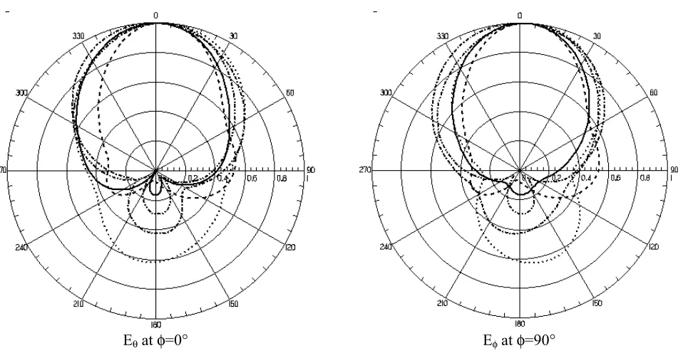
All the results for different sizes are summarized in Table 2 including the results in case of infinite ground plane. The simulated co-polarization radiation patterns of the antenna are also shown in Figure 5, while the air gap is g = 0. It can be observed that patterns differ from those of
the infinite ground plane at angles close to the ground. Also there is a backward radiation in θ=π° direction, which would lower the gain of the antenna. The variations of the resonance frequency, directivity and backward lobe for E- and H-plane co-polarization patterns are shown in Figure 6.
It can be seen that the resonance frequency is not considerably affected (maximum 1.5%) by the size of the ground plane, whereas the directivity, quality factor and impedance bandwidth vary significantly when the ground plane is less than 0.6λ0.
4.3 The Air Gap Effect
To investigate the effect of the gap in the antenna structure, a few simulations were carried out for different situation. First an air gap, g, between the resonator and ground plane is considered. This could be due to the roughness of the resonator surface or failure to ensure complete contact between the resonator and conducting parts of the structure. In this case the electric field component normal to the metallic parts of the structure is much stronger in the air gap than it is just inside the resonator, especially, when it is composed of a material of high dielectric constant and this, significantly affects the radiation performance of the DRA antenna. The effect of the air gap g can be explained by considering the resonator and the gap as a single dielectric object of the height (h+g) made partly of air and partly of high dielectric constant εr = 38. The result is anobject with an effective dielectric constant lower
x
z
0.2 mm
port
g
than 38, which results in higher resonance frequency and lower Q-factor.
The air gap g between the ground plane and the DR is increased from zero to maximum value of 2 mm, while the length of the probe keeps equal to the (h+g). Figure 7 shows the simulated results of the variations of the resonance frequency versus the gap g Results indicate that the air gap causes that the resonance frequency to shift upward. Moreover, it is shown that higher directivity, lower quality factor and as a result broader impedance bandwidth is obtained [19].
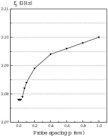
The effect of the air gap between the resonator and feed probe is also considered for various probes spacing p for the same resonator positioned at the centre of the circular ground plane with a 100mm diameter. The probe length is set to the height of the resonator l = h and also g is kept equal to 0. The probe spacing is varied from 0 mm to 1 mm measured from the edge of the probe to the edge of the resonator.
Results show that introducing a very tiny separation between the resonator and probe, the coupling between resonator and probe is increased and the optimal coupling occurs at p=0.035mm.
On the other hand, increasing p from optimal value would decrease the coupling [20]. The variations of resonance frequency versus p are shown in Figure 8. It can be seen that f0 does not change for
small values of p. However, further increase in p from 0.035mm results in increasing the resonance frequency by a maximum 0f 1% at p=1mm.
5. MEASUREMENT
In order to evaluate the accuracy of the theoretical modeling and numerical results a few experimental set-ups of the RDRA structures have been studied experimentally. Figure 9 shows the cross section of the antenna for measurement. The resonator is placed on a metallic ground plane with 6mm thickness. An SMA connector is used whereas the internal conductor is extended above the ground plane as the probe to excite the resonator. The dimensions of the resonator are 19, 19, and 9.5 mm and r = 38. Experiments have been performed
using a few ground plane sizes. The HP-8510 automatic network analyzer is used at the output
Eθ at φ=0° Eφ at φ=90°
power of +10dBm to measure the return loss to obtain the resonance frequency and the radiation patterns in an anechoic chamber. Using calibrated dipoles, the antenna gain was measured and
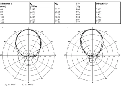
unloaded quality factor Q0 was calculated from the return loss versus frequency plot. Figure 10 shows the measured radiation patterns for different ground plane size and other parameters are
25 50 75 100 125 2.02
2.03 2.04 2.05 2.06 2.07 2.08
f
0(GHz)
Ground plane diam eter d (m m )
2 5 5 0 7 5 1 00 1 25 2 .0
2 .5 3 .0 3 .5 4 .0 4 .5 5 .0
D
Ground plane diam eter d (m m )
25 50 75 100 125
-12 -10 -8 -6 -4 -2 0
H-Plane E-Plane
Backw ard
Lobe
(dB)
G round
pl
ane
di
am et
er
d
(m m )
summarized in Table 3.
It can be observed that, there is a backward radiation in θ=π° direction, which decreases for larger ground plane. Also the patterns differ from those of infinite ground plane at angles close to the ground plane. The backward radiation would lower the gain of the antenna as is clear in the directivity versus ground plane diameter.
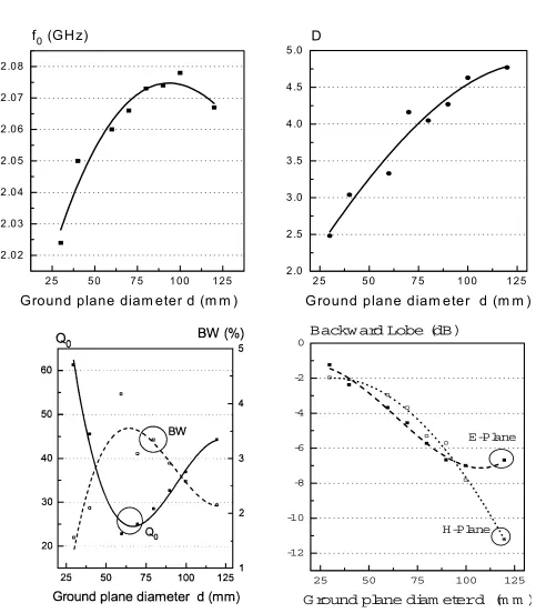
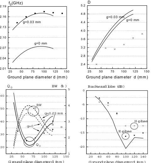
The variations of the resonance frequency, directivity, Q-Factor, Bandwidth and backward lobe including curves of the simulation considering the effect of the gap using the numerical results are shown in Figure 11. It can be seen that there is 1.4% change in the resonance frequency, when diameter changes from 40mm to 140mm. The measured resonance frequency agreed well with simulation results, when air gap of 0.03mm between the resonator and the ground plane is considered in simulation.
Also directivity graphs show that increasing the diameter of the ground plane lead to increasing directivity, which is due to decreasing the
backward radiation. Moreover, not such a good agreement is obtained for the numerical results of the directivity which is believed to be due to the lack of convergence in run time of the simulation by the HFSS.
0.0 0.5 1.0 1.5 2.0 2.0
2.2 2.4 2.6 2.8 3.0 3.2 3.4
f0 (GHz)
Gap g (mm)
Figure 7. The simulated variations of the resonance frequency of the probe-fed RDRA versus the air gap g.
0.0 0.2 0.4 0.6 0.8 1.0
2.07 2.08 2.09 2.10 2.11
f0 (G Hz)
Probe spacing p (m m )
Figure 8. The simulated variations of the resonance frequency of the probe-fed RDRA versus the probe spacing p.
x z
4.1 mm d = 1.3 mm
6 mm 9.5 mm 7 mm
port
ε =1.9
6. RESULTS AND DISCUSSION
The radiation characteristics of a probe-fed rectangular DRA with relative dielectric constant
εr=38 residing on infinite ground plane, was
predicted by analytical model based on the CDWM and the resonance frequency, quality factor and radiation patterns were obtained. A numerical method was also used to consider finite size of the ground and fabrication imperfections such as air gap in the antenna structure.
Results show that predicted radiation patterns using the CDWM and numerical method agree well in case of infinite ground plane. However, in case of finite plane radiation patterns depend on the size of the ground and could vary from those of the infinite plane, particularly when the diameter is
less that a half of the wavelength. The finite size of the ground would result in backward radiation and as a result, lower the directivity of the antenna. It can be observed that as the diameter of the ground plane is increased no significant changes can be seen for the patterns in the broadside direction but, the backward radiation, as shown in Figure 11, is considerably reduced. This leads to an increase in directivity. It is anticipated that by further increase in diameter, from nearly 120cm, no significant change will be observed in backward radiation, but broader E-plane pattern is obtained and hence directivity tends to the value in case of infinite ground plane.
The resonance frequency could change by 1.5% when the ground plane diameter is changed from 40mm to 120mm. It can also be observed that TABLE 3. Experimental Results of the Probe-Fed RDRA for Different Ground Plane.
Diameter d (mm)
f0
(GHz)
Q0 BW
(%)
Directivity
40 2.142 32.55 3.04 2.403
60 2.160 25.05 3.96 3.217
80 2.162 27.20 3.64 3.127
100 2.175 30.96 3.20 3.344
120 2.173 33.84 2.93 3.655
140 2.170 35.71 2.77 3.855
Eθ at φ=0° Eθ at φ=90°
when air gap between resonator and ground plane, g, is assumed to be zero, the results of the HFSS and experiments differ by ∼5% for resonance
frequency. However, considering g= 0.030mm, the accuracy improves to ∼0.15%. The simulated results also agree well with those obtained by
25 50 75 100 125 150 2.01
2.04 2.07 2.10 2.13 2.16 2.19
g=0.03 mm
g=0 mm
f
0(GHz)
Ground plane diam eter d (m m )
25 50 75 100 125 150 2.4
2.8 3.2 3.6 4.0 4.4 4.8 5.2
g=0.03 mm
g=0 mm
D
Ground plane diam eter d (m m )
25 50 75 100 125 150
20 30 40 50 60
BW
(% )
BW
Q
0
g=0
g=0.03 m m
Q
0G round
pl
ane
di
am et
er
d
(m m )
1 2 3 4 5
20 40 60 80 100 120 140
-20 -15 -10 -5 0
H-plnae
E-plnae
Backward
l
obe
(dB)
G round
pl
ane
di
am et
er
d
(m m )
experiments for quality factor and impedance bandwidth, considering the air gap. The predicted directivity of the RDRA using HFSS does not have a good agreement with the CDWM and experimental results and error can be as high as 35%. This is believed to be due to lack of convergence in the numerical solution at the allowed run time of simulation.
7. CONCLUSION
In this paper an analytical method was presented for predicting the radiation performance of a probe-fed RDRA in case of infinite ground plane. To consider the effect of the finite size of ground plane and fabrication imperfections in antenna structure, a numerical method using the HFSS was employed and radiation characteristics of the antenna were studied. The predicted results also were experimentally verified for several ground planes.
Results show that the CDWM can be used as a first estimation of the antenna parameters in case of infinite ground. However, better results compare to experiments, can be obtained using the HFSS. The finite size of the ground plane and also air gap has a significant effect on the performance of the antenna, which needs to be taken into account. Moreover, the length of a probe also alters the radiation performance of the RDRA, which needs further investigation.
8. REFERENCES
1. Fiedziuszko, S. J., “Microwave Dielectric Resonators”,
Microwave Journal, (September 1986), 189-200. 2. Long, S. T., McAllister, M. W. and Shen, L. C., “The
Resonant Cylindrical Dielectric Cavity Antenna”, IEEE Transactions on Antenna & Propagation, Vol. AP-33, (1983), 406-412.
3. McAllister, M. W., Long, S. A. and Conway, G. L., “Rectangular Dielectric Resonator Antenna”, Electronics Letters, Vol.19, (1983), 218-219.
4. McAllister, M. W. and Long, S. A., “Resonant Hemispherical Dielectric Antenna”, Electronics Letter, Vol. 20, (1984), 657-659.
5. Mongia, R. K., Ittipiboon, A., Antar, Y. M. M., Bhariat P. and Cuhaci, M., “A Half Spilt Cylindrical Dielectric Resonator Antenna Using Slot Coupling”, IEEE Microwave and Guided Waves Letters, Vol.3, (1993a),
38-39.
6. Mongia, R. K., Ittipiboon, A., Bharita, P. and Cuhaci, M., “Electric Monopole Antenna Using a Dielectric Ring Resonator”, Electronics Letters, Vol.29, (1993b), 1530-1531.
7. Kranenburg, R. A. and Long, S. A., “Microstrip Transmission Line Excitation of Dielectric Resonator Antennas”, Electronics Letters, Vol. 24, (1988), 1156-1157.
8. Martin, J. T. H. S., Antar, Y. M. M., Kishk, A. A., Ittipiboon, A. and Cuhaci, M., “Dielectric Resonator Antenna Using Aperture Coupling”, Electronics Letters, Vol.26, (1990), 2015-2016.
9. Kranenburg, R. A., Long, S. A. and Williams, J. T., “Coplanar Waveguide Excitation of Dielectric Resonator Antennas”, IEEE Transactions on Antennas & Propagation, Vol. AP-39, (1991), 119-122.
10. Kishk, A. A., Auda, H. A., and Ahn, B. C., “Radiation Characteristics of Cylindrical Dielectric Resonator Antennas with New Applications”, IEEE Antennas and Propagation Society Newsletter, (1989), 7-16.
11. Wu, Z., Drossos, G., Jusoh, M. A., Sha, J. and Davis, L. E., “Cylindrical Dielectric Resonator Antennas Supported by Infinite and Finite Ground Planes”,
International Conference on Antenna and Propagation (ICAP'97), Edinburgh, UK, (1997), 1.486-1.489. 12. Junker, G. P., Kishk, A. A., Glisson, A. W. and Kajfez,
D., “Effect of an Air Gap around the Coaxial Exciting a Cylindrical Resonator Antenna”, Electronics Letters, Vol. 30, (1994), 177-178.
13. Junker, G. P., Kishk, A. A., Glisson, A. W. and Kajfez, D., “Effect of Fabrication Imperfections from Ground Plane Backed Dielectric Resonator Antenna”, IEEE Antennas & Propagation Magazine, Vol. 37, (1995), 40-47.
14. Mongia, R. K., and Ittipiboon, A., “Theoretical and Experimental Investigations on Rectangular Dielectric Resonator Antennas”, IEEE Transactions on Antenna & Propagation, Vol. Ap-45, (1997), 1348-1356. 15. Neshati, M. H. and Wu, Z., “Probe-fed Rectangular
Dielectric Resonator Antennas: Theoretical Modeling & Experiments”, International Journal of Engineering (IJE), Tehran Iran, Vol. 16, No. 1, (2003), 41-46..
16. Balanis C. A., “Advanced Engineering Electromagnetic”, John Wiley & Sons, (1989).
17. Hewlett-Packard, (1994), HP85180A High Frequency Structure Simulator. User's Reference.
18. Wu Z., and Davis L. E., “Automation-Oriented Techniques for Quality-Factor Measurement of igh Tc Superconducting Resonators”, IEE Proceedings of Science, Measurement & Technology, Vol. 141, (1994) 427-430.
19. Neshati, M.H., “Numerical Modeling and Application Studies of the RDRA”, PhD Dissertation, UMIST, Manchester, UK, (2001).