RESEARCH NOTE
A PROPOSED METHOD TO EVALUATE ULTIMATE
RESISTANCE OF PLATE GIRDERS SUBJECTED
TO SHEAR AND PATCH LOADING
F. Shahabian and H. Haji-Kazemi
Department of Civil Engineering, Faculty of Engineering Ferdowsi University of Mashhad, Iran
ejour@ferdowsi.um.ac.ir - fshahabianm@yahoo.com
(Received: January 15, 2001 – Accepted in Revised Form: August 18, 2004)
Abstract Experimental investigation of the ultimate resistance of slender, steel-plate girder web panels to combined shear-and-patch loading indicates significant interaction between shear loading and patch loading. However, an existing interaction formula is based on experimental results. Herein, an improved design procedure for slender plate girders subjected to combined shear and patch loading is proposed. A modified formula to evaluate shear resistance of plate girders in presence of patch loading is proposed that shows satisfactory correlation with the available test data and is acceptable for practical purposes.
Key Words Plate Girders, Combined Shear and Patch Loading, Modified Shear Resistance
ﻩﺪﻴﻜﭼ
ﻩﺪﻴﻜﭼ
ﻩﺪﻴﻜﭼ
ﻩﺪﻴﻜﭼ
ﻲﺳﺭﺮﺑ ﻥﺎﻣﺰﻤﻫﻲﻌﺿﻮﻣﻭﻲﺷﺮﺑﻱﺎﻫﻭﺮﻴﻧﻪﻛﺖﺳﺍﻩﺩﺍﺩﻥﺎﺸﻧﻲﺑﺮﺠﺗﻱﺎﻫ ﺶﻨﻛﺭﺪﻧﺍ
ﺭﺩﻱﺍﻪﻈﺣﻼﻣﻞﺑﺎﻗ
ﺖﺷﺍﺩ ﺪﻨﻫﺍﻮﺧ ﺎﻬﻗﺭﻭ ﺮﻴﺗ
. ﻩﺩﺯﻦﻴﻤﺨﺗ ﺕﺎﺸﻳﺎﻣﺯﺁ ﺯﺍﻞﺻﺎﺣ ﺞﻳﺎﺘﻧ ﺱﺎﺳﺍﺮﺑ ﹰﺎﺗﺪﻤﻋ ﺱﺮﺘﺳﺩ ﺭﺩ ﺩﻮﺟﻮﻣ ﻂﺑﺍﻭﺭ
ﺪﺷ ﺪﻧﺍﻩ
. ﻲﻌﺿﻮﻣﻭﻲﺷﺮﺑﻥﺎﻣﺰﻤﻫﺭﺎﺑﺮﺛﺍﺖﺤﺗﻱﺎﻫﻕﺭﻭﺮﻴﺗﻱﺍﺮﺑﻲﺣﺍﺮﻃﻪﺘﻓﺎﻳﺩﻮﺒﻬﺑ ﺵﻭﺭﻚﻳ ،ﻪﻟﺎﻘﻣﻦﻳﺍﺭﺩ
ﺖﺳﺍﻩﺪﺷﺩﺎﻬﻨﺸﻴﭘﺎﻬﻗﺭﻭﺮﻴﺗﻲﺷﺮﺑﺖﻣﻭﺎﻘﻣﻦﻴﻤﺨﺗﺖﻬﺟﺰﻴﻧﻱﺍﻪﻄﺑﺍﺭﻭﻩﺪﺷﻪﺋﺍﺭﺍ
.
ﻭﻝﻮﺒﻗﻞﺑﺎﻗﻖﺑﺎﻄﺗﻪﻄﺑﺍﺭﻦﻳﺍ
ﺩﺭﺍﺩﻲﺑﺮﺠﺗﺞﻳﺎﺘﻧﺎﺑﻲﺒﺳﺎﻨﻣ
.
1. INTRODUCTION
Slender steel plates are used in a variety of structural engineering applications owing to their high strength-to-weight ratio and post-buckling reserve of stiffness and strength. Typical structural forms are slender-plate and bog girders, in which the flanges primarily resist bending and the web primarily, resist shear and localized, in-plane, compressive edge loading, often described as patch loading.
Shear loading and localized edge or patch loading of slender plate girders are frequently encountered in practice. Significant shear loading arises from nonuniform bending and support reactions, while examples of patch loading are wheel loads on gantry girders, loads from purlins onto the mainframe members of buildings, and
Herein, details of a theoretical investigation of the ultimate shear resistance of slender web panels in the presence of patch loading is presented. Theoretical predictions are compared with available experimental results and a modified formula for combined shear-and-patch loading is proposed.
2. THEORETICAL PREDICTION OF ULTIMATE SHEAR RESISTANCE
Theoretical predictions of the ultimate shear resistance of slender web panels can be made in accordance with tension field theory, developed by Porter et al. [6] and Evans [1]. For a web panel having width bw, depth dw, thickness tw, and similar top and bottom flanges (Figure 2), the ultimate
shear resistance Vu is given by
) w b cot w d ( 2 sin w t y t w t w d cr u
V =τ +σ θ θ− ) y t * p M yw ( sin w t w d 4
+ θ σ σ (1)
cr
τ
is the critical shear stress of an assumed simply supported web plate, given byd ) 1 ( 12 Et K 2 w 2 2 w 2 s cr ν − π =
τ (2)
where Ks is buckling coefficient.
σ
yt is the web tension field membrane stress, defined by the equation yw yw cr 2 2 yw cr y t 2 sin 2 3 2 sin 4 3 1 1 σ θ τ τ − − θ
τ τ − = σ (3) where
τ
yw is shear yield stress of the web. Whichis related to the uniaxial yield stress
σ
yw by the equation3
yw ywσ
=
τ
(4)θ
is the inclination of the web tension field, assumed to be approximately two-thirds of the inclination of the web panel diagonal, i.e., = θ − w w 1 b d tan 3 2 (5) * p
M
is a nondimensional flange strength parameter defined as yw w 2 w pf * p t d M M σ= (6)
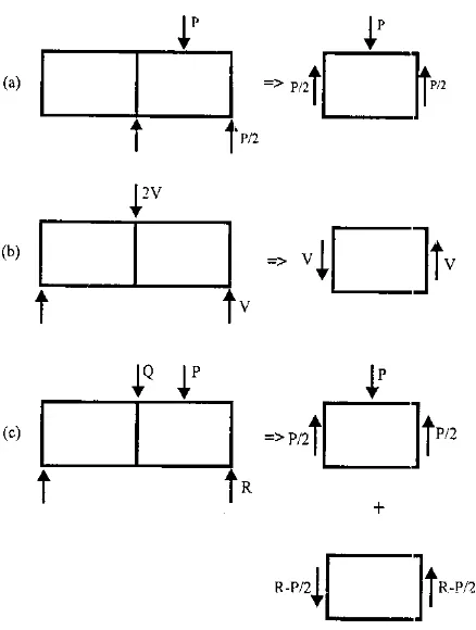
Figure 1. Shear-and patch loading of plate girders: (a) Pure
where Mpf is fully plastic moment of the flange, which for a rectangular flange having width bf,
thickness tf, and yield stress
σ
yf is given byyw 2 f f pf
0
.
25
b
t
M
=
σ
(7)3. THEORETICAL PREDICTION OF ULTIMATE PATCH RESISTANCE Theoretical predictions of the ultimate patch resistance of slender web panels can be made in accordance with the theory developed by Roberts and Newark [3]. The ultimate patch resistance Pu should be taken as the lesser of the resistance to web-crippling Pub, and web-yielding Puy which are given by
(
)
F
1
t
d
t
c
1
t
t
E
t
1
.
1
P
f w
w e 25
. 0
w f 5 . 0 yw 2 w ub
+
σ
=
(8)
(
)
yw w e5 . 0 w yw pf
uy
16
M
t
t
c
P
=
σ
+
σ
(9)where F is a numerical factor to be taken as 1.45 for a lower bound 95% confidence limit and 1.0 for a mean prediction and ce is the effective length of the patch load, which is related to the actual length
c by the equation
f e
c
2
t
c
=
+
(10)4. INTERACTION BETWEEN SHEAR AND PATCH RESISTACE
When a girder web subjected to patch loading in addition to shear, the determination of the ultimate load capacity becomes more complex. Analysis of test results for combined shear and patch loading conducted by first author indicates significant interaction between the two forms of loading [7]. The following interaction formula for this combined loading is proposed that shows satisfactory correlation with the test data.
0 . 1 P P V
V
u dc 2
u dc
≤ +
(11)
In which Vdc and Pdc are the design shear and patch loads for combined loading, and Vu and is the ultimate shear resistance in the absence of patch loading, and Pu is the ultimate patch resistance in the absence of shear.
due to the patch stresses.
(b) The influence of the patch stresses upon the magnitude of the membrane stresses required producing yield in the web.
Each of these factors will now be considered individually.
(a) Evaluation of the Shear Buckling
Resistance
When the web panel is subjected to combined patch loading and shear, the bucklingcoefficients are determined by the author from the following interaction formula [8]
0 . 1 K
K K
K
p ps
s sp
= +
α α (12)
where Ksp and Ks are the buckling shear coefficients in the presence and absence of patch loading, respectively, and Kps and Kp are the Figure 3. State of stresses in the seb plate girder.
buckling patch coefficients in the presence and absence of shear, respectively.
α
is given by3 2
0
.
05
77
.
0
77
.
0
1
.
2
−
β
+
β
−
β
=
α
(13)in which
w w
d
b
=
β
(14)In each case, the buckling load Pcr can be expressed as
w 2
3 w 2
p cr
d ) l ( 12
Et K
P
ν − π
= (15)
Thus, for any patch load P, by substituting
cr p ps
P
P
K
K
=
in Equation 12, the value of the modified shear buckling stress τcrmis determined.s sp cr crm
K K
τ =
τ (16)
(b) Evaluation of the Membrane Stresses
The state of stress in the web plate for combined shear and patch loading is shown in Figure 3. The total state of stress in the web plate may be obtained by superimposing all the stresses as shown in Figure 4 and may be defined as follows
θ σ − σ − θ τ
=
σθ crmsin2 tm psin2 θ σ − θ τ
− =
σθ+90 crmsin2 pcos2 (17) θ
σ − θ τ
=
τθ crmcos2 2p sin2
Upon further increase of the applied loading, the tensile membrane stress (σtm) developed in the web increases. Eventually, the membrane stress reaches such a value that, when combined with the buckling stress as in Equations 17, the resulting TABLE 1. Girder Dimensions and Material Yield Stresses [5].
Plate
Girder (mm) bw (mm) Dw (mm) tw (mm) bf (mm) tf (N/mmσyw 2)
yf
σ
stress (σθ) reaches the yield value (σyw) for the web material. This value of the membrane stress will be denoted as y
tm
σ and it may be determined by applying the Von Mises-Hencky yield criterion:
2 yw 2 90 2 90
2 +σ −σ σ +3τ =σ
σθ θ+ θ θ+ θ (18)
By substituting the stresses from Equations 17, the following modified expression for the membrane stress is obtained.
) 4 2 sin 3 -2 sin 2 cos 12 2 cos 12 cos 3 cos 2 sin 6 2 sin 3 ( 2 1 cos 2 1 sin 2 sin 2 3 5 . 0 2 yw 2 2 p p crm 2 2 crm 4 2 p 2 p crm 2 2 crm 2 p 2 p crm y tm σ + θ σ θ θσ τ + θ τ − θ σ − θ θσ τ − θ τ − + θ σ − θ σ + θ τ − = σ (19) where σp is the value of the patch stress is given by
(
)
yw u cr pP
P
P
σ
−
γ
=
σ
cr P P 0 ≤ = γ u cr P 0.9P P
1 ≤ ≤
= γ u u cr
P
P
0.9P
P
P
P
≤
≤
−
=
γ
(20)5. PROPOSED FORMULA TO EVALUATE THE MODIFIED SHEAR RESISTANCE
The modified shear resistance of the plate girder may be obtained approximately from the following formula ) b cot d ( sin t t d
V w w
2 w y tm w w crm
um =τ +σ θ θ−
(
M)
sin t d 4 y tm * p yw w
w θ σ σ
+
(21) Comparison of the ultimate shear resistance and
modified shear resistance in accordance with Equations 1 and 21, shows the values of τcr and σty have been replaced with the τcrmand σytm, respectively.
6. COMPARISON OF THE PROPOSED METHOD WITH EXPERIMENTAL AND
THEORETICAL RESULTS
A total of 32 specimens were constructed and tests (two tests per girder) have been conducted on slender-plate girders, details of which are shown in Figure 2. The dimensions of the test girders denoted PG2-1 to PG4-3, are given in Table 1.
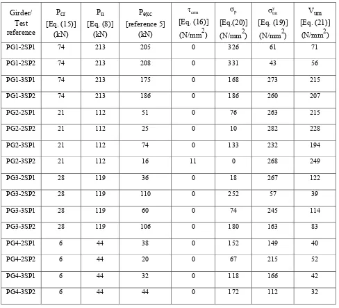
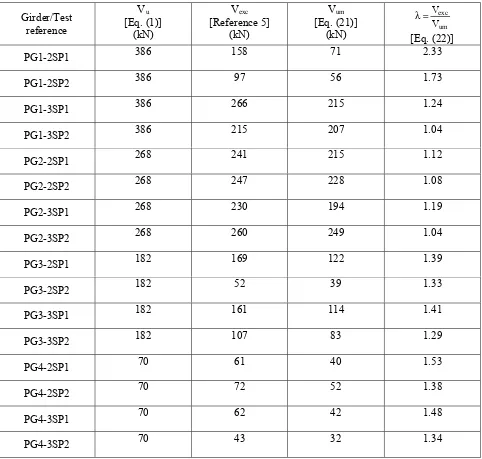
The modified shear resistance (Vum) of the plate girders determined in accordance with Equation 21 is presented in Table 2. To evaluate Pu used in Table 2, the numerical factor F in Equation 8 was assumed equal to 1.0 to provide a mean prediction. The theoretical ultimate shear resistances (Vu) in the absence of patch loading, determined in accordance with Equation 1, are compared with experimental results (Vexc) and the proposed formula (Vum) in Table 3 and in Figure 5.
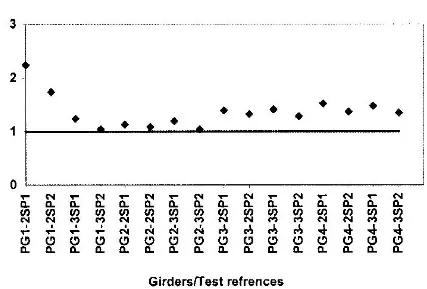
Also, as presented in Table 3 and Figure 6, values of λ are determined as follows
1
V
V
um exc≥
=
λ
(22)All the values of λ are greater than unity, indicating a safe and conservative design procedure.
7. DISCUSSION AND CONCLUTIONS
rigorous solution.
Herein, the shear resistance of plate girders in the presence of patch loading has been investigated, theoretically. A modified formula for this combined loading is proposed that shows satisfactory correlation with the available test results. The solution presented is acceptable for practical purposes.
8. NOMENCLATURE bf Width of flange
bw Clear width of web plate between stiffeners c Length of Patch load
ce Effective length of patch load dw depth of web panel
E Young’s modulus TABLE 2. Modified Shear Resistance in Accordance with the Proposed Formula.
Girder/ Test reference
Pcr [Eq. (15)]
(kN)
Pu [Eq. (8)]
(kN)
Pexc [reference 5]
(kN)
crm τ [Eq. (16)]
(N/mm2)
p
σ
[Eq.(20)] (N/mm2)
y tm
σ
[Eq. (19)] (N/mm2)
Vum [Eq. (21)]
F Numerical factor
Kp Buckling coefficient for patch loading Kps Buckling coefficient for combined patch
loading and shear
Ks Buckling coefficient for shear
Ksp Buckling coefficient for combined shear and patch loading
* p
M
Flange strength parameterMpf Plastic moment of flange P Patch load
Pcr Buckling patch load
Pdc Design patch load for combined loading Pexc Experimental ultimate patch resistance to
combined shear-and-patch loading Pu Theoretical ultimate patch resistance Pub Theoretical ultimate patch resistance to
TABLE 3. Comparison of Proposed Method with Test Results and Theoretical Predictions.
Girder/Test reference
Vu [Eq. (1)]
(kN)
Vexc [Reference 5]
(kN)
Vum [Eq. (21)]
(kN) um
exc V V = λ
[Eq. (22)]
PG1-2SP1 386 158 71 2.33
PG1-2SP2 386 97 56 1.73
PG1-3SP1 386 266 215 1.24
PG1-3SP2 386 215 207 1.04
PG2-2SP1 268 241 215 1.12
PG2-2SP2 268 247 228 1.08
PG2-3SP1 268 230 194 1.19
PG2-3SP2 268 260 249 1.04
PG3-2SP1 182 169 122 1.39
PG3-2SP2 182 52 39 1.33
PG3-3SP1 182 161 114 1.41
PG3-3SP2 182 107 83 1.29
PG4-2SP1 70 61 40 1.53
PG4-2SP2 70 72 52 1.38
PG4-3SP1 70 62 42 1.48
web crippling
Puy Theoretical ultimate patch resistance to
web yielding R Reaction at support Figure 5. Comparison of proposed method with test results.
tf Thickness of flange tw Thickness of web V Shear load
Vdc Design shear load for combined loading Vexc Experimental ultimate shear resistance to
combined shear–and-patch loading Vu Theoretical ultimate shear resistance
Vum Modified ultimate shear resistance to combined shear-and-patch loading
Greek Symbols
α
Function of ββ
Aspect ratio (bw/dw)γ
Numerical factor for patch stress θ Inclination of web tension field λ Design factor (defined by equation 21)ν
Poisson’s ratioy t
σ
Tension field membrane stress at yield ytm
σ
Modified tension field membrane stress at yieldyf
σ
Yield stress of flange ywσ
Yield stress of web θσ
Normal stress crτ
Buckling shear stress crmτ
Modified buckling shear stressyw
τ
Yield shear stress of web θτ
Shear stress9. REFERENCES
1. Evans, H. R., “Longitudinally and Ttransversely Reinforced Plate Girders”, Plated Structures, Stability and Strength, R. Narayanan, Elsevier, Applied Science, London, (1983), 1-37.
2. Lee, S. C. and Yoo, C. H., “Strength of Plate Girder Web Panels under Pure Shear”, J. Struct. Engrg, ASCE, Vol. 124, No. 2, (1998),184-194.
3. Roberts, T. M. and Newark, C. B., “Strength of Webs Subjected to Compressive Edge Loading”, J. Struct.
Engrg, ASCE, Vol. 123, No. 2, (1997), 176-183.
4. Elgally, M. and Seshadri, A., “Girders with Corrugated Webs under Partial Compressive Edge Loading”, J.
Struct. Engrg, ASCE, Vol. 123, No. 6, (1997), 738-791.
5. Shahabian, F. and Roberts, T. M., “Combined Shear and Patch Loading of Plate Girders”, J. Struct. Engrg, ASCE, Vol. 126, No. 3, (2000), 316-321.
6. Porter, D. M., Rockey, K. C. and Evans, H. R., ”The Collaps Behaviour of Plate Girders Loaded in Shear”, The
Struct. Engr., Vol. 53, No. 8, (1975), 313-325.
7. Roberts, T. M. and Shahabian, F., “Design Procedures for Combined Shear and Patch Loading of Plate Girders”, Proc. Instn. Civ. Engrs. Structs. and Bldgs., Vol. 140, (2000), 219-225.


![TABLE 1. Girder Dimensions and Material Yield Stresses [5].](https://thumb-us.123doks.com/thumbv2/123dok_us/243451.2019047/5.595.55.548.97.354/table-girder-dimensions-material-yield-stresses.webp)