I. Introduction
The demand for fossil fuel has increased in recent decades. One of the main reasons is the dramatically in-crease in personal vehicles produced each years which mainly powered by conventional internal combustion en-gines (ICEs). Due to the limitation of fossil fuel resources aside from the environmental aspects of using these kinds of fuels such as global warming, emissions released dur-ing combustion process and etc., electric vehicle (EVs) and FCVs are considered as attractive alternatives for ICEs.
In FCVs, unlike the conventional ICEs, the main power source is a fuel cell (FC) system. A battery pack is also used in order to generate the demanded peak power in ve-hicle drive cycles. Furthermore, during the start-up process of the fuel-cell the battery supplies the energy of the vehicle. A FC is generally supplied with hydrogen fuel and air [1]. Its output voltage is too low to supply the high-performance drive systems in vehicular power rat-ings [1, 2]. In fact, based on efficiency characteristic of the FC, even though it operates more efficient at lower temperatures, operation in high temperatures is inevitable because of the higher output voltage of the FC in this
dition [3]. Besides, this output voltage should be con-trolled and regulated at a desired voltage. Therefore, a step-up DC-DC converter should be adopted [4]-[6]. Uti-lizing this converter results in running the FC in lower temperature operating points which are more efficient. Among many different types of FCs, proton exchange membrane FCs (PEMFC) have the ability to operate at very low temperatures [3]. Owing to this feature and some other advantages they are almost the first candidate to be used in vehicular applications. Many topologies have been introduced in literature for DC-DC converter used in renewable energies such as FC applications [7]-[12].
The current ripple drawn from FC stacks has a major impact on its performance and durability [13, 14]. There-fore, the DC-DC converter which is used to regulate the DC-link voltage should have a proper input current char-acteristic. Converters proposed in [7]-[9] utilize coupled inductors and their input current ripple is relatively high. In [10]-[12] coupled inductors are used to increase the voltage conversion ratio in voltage multiplier cell. How-ever, additional windings in high-power application not only complicates the design process, but also increase the overall power loss. Due to the low input current ripple, power splitting feature and high reliable operation of the interleaved converters, it is better to utilize these kinds of converters in high-power application. The reliability of these sorts of converters is discussed in [15]. Converters in [8, 9] and [12] are suitable for lower power demands.
In this paper a new DC-DC interleaved converter with a simple structure and reduced switch voltage stress is proposed. Low power dissipation, proper input current
A Novel Interleaved DC-DC Converter with Reduced
Loss for Fuel Cell Vehicle Application
M. Khalilzadeh*, B. Asaei*(C.A.)and M. R. Nikzad*
Abstract: In this paper a novel four-leg interleaved DC-DC boost converter is proposed which is well
suit-able for fuel cell vehicles (FCV) application. The voltage stress of two switches of this converter is half of the conventional interleaved converters. Therefore, smaller and cheaper switches can be utilized. Also "on" state duration of the two of four switches are reduced in comparison with conventional converter. Further-more, comparing the losses of the proposed converter to conventional one – which is used in ،Toyota Mirai 2015 – shows a significant loss reduction in full power range. The proposed converter is simulated within an FCV in urban and highway driving cycles using ADVISOR software. The results show that the average power loss of the converter is improved about 32% in urban cycle and about 17% in highway cycle com-paring to conventional one.
Keywords: Fuel cell vehicle, Interleaved DC-DC converter, Converter loss calculation, Loss reduction,
Toyota Mirai 2015.
Iranian Journal of Electrical & Electronic Engineering, 2017. Paper received 16 August 2016 and accepted 8 April 2017.
* The authors are with the School of Electrical and Computer Engineer-ing, University of Tehran, Tehran, Iran.
E-mails: m.khalilzadeh@ut.ac.ir, basaei@ut.ac.ir and nikzad@ut.ac.ir. Corresponding Author: B. Asaei.
profile, simple and modular structure, make this converter a good candidate for high power applications.
2. Operation Principles of the Proposed Converter Fig. 1(a) and Fig.1 (b) show the circuit configuration of a four-leg conventional interleaved DC-DC converter used in Toyota Mirai 2015 and the proposed converter, re-spectively. The proposed converter consists of a conven-tional two-leg (phase) interleaved boost converter combined with another interleaved converter with voltage multiplier cell. Two upper switches are driven similar to
a conventional two-leg interleaved converter with 50% phase shifted drive signals. Two lower switches are driven with 50% phase shifted signals with respect to each other in a way that the voltage gain of the upper and lower stages forced to be same. Hereafter, the operation of the lower side of the proposed converter will be further de-tailed. The upper side operation is the same as a conven-tional interleaved converter, so it is not discussed here. Circuit topology in each interval and the current-flow paths are illustrated in Fig. 2. Fig. 3 shows some of the typical key-waveforms of the proposed converter.
Fig.1.Circuit configuration of the(a) conventional interleaved converter used in Toyota Mirai 2015(b) proposed converter
Fig. 2. Circuit topology and current paths in each operation interval (in the lower stage). (a) Interval 1&3, (b) Interval 2 (c) Interval 4
Interval 1: In this mode of operation both of the lower switches (S3 & S4) are in "on" state. The input current splits between two inductors equally and energizes them. Output capacitor supplies the load power. This interval ends when S4 is turned into "off" state. Fig. 2(a) depicts the current-flow path of this mode of operation.
Interval 2: During this interval switch S3 is still on and S4 is in "off" state. Diode Dm2 and D4 are forward bi-ased and are conducting the current. Therefore, C1 is en-ergized and C2 is discharged into the output capacitor (Co). Furthermore, the current of inductor L3 is still in-creasing but inductor L4 is discharging its energy. As the same values are selected for the capacitors C1 and C2, the steady-state voltages of these capacitors are the same and equal to half of the output voltage of the converter. This mode of operation is lasted till S4 is off. Fig. 2(b) illus-trates the circuit topology of interval 2 of the proposed converter.
Interval 3: This interval is similar to the interval 1, as shown in Fig. 2(a).
Interval 4: This interval is similar to interval 2 but un-like that, the switching condition of S3 and S4 are toggled. Therefore, L4 is in charging and L3 is in discharging mode. The circuit topology in this interval is depicted in
Fig. 2(c).
The voltage gain of the conventional stage is denoted in (1) as follows:
(1)
As mentioned before, the voltage of the capacitor C2 equals to half of the output voltage. Therefore, one can write the volt-second balance equation for inductor L4 in the switching period (Ts) as follows:
(2)
Considering in (2), the voltage gain of the lower stage can be calculated as:
(3)
The input and output voltages of each stage are the same as the other stage. So the voltage gains should be same too. Therefore, results in:
(4)
Equation (4) is used in controlling of the proposed topology in order to generate the switching commands. The steady-state "off" state voltage of the two lower switches is given in Eq. (5). As mentioned before, this voltage is half of the voltage of the switches of a conven-tional boost converter, resulting in lower loss and lower price in the proposed converter.
(5)
In order to calculate the losses of the proposed con-verter and compare them with conventional interleaved boost converter, Eq. (6) and (7) are used [16, 17] where (6) denotes the losses related to switches (IGBTs) and (7) indicates the losses of diodes. These formulas include switching loss and conduction loss.
(6) 1 1 1 1 o in V M
V - D
§ · ¨ ¸ ¨ ¸ © ¹ c o
L T s s in in o
V V Ͷ T D Vʹ D Vʹ V
ʹ ( - - ) o in V M
V - D ʹ ʹ ʹ ͳ D D ʹ ͳ ͳ ʹ o S S
V
V
͵Ƭ Ͷʹ
2
IGBT IGBT
Loss ceo c,avg c c,RMS on
P U I r I (E E
IGBT off rr s
E E ) f
Int.2 Int.4
S1
S2
S3
S4
i
Dmi
Li
LIDm2 IDm1
IL2
IL1
IL3 IL4
Ts
D2Ts D1Ts
D’2Ts D’1Ts 0.5Ts
Fig. 3. The key waveforms of the proposed converter in CCM
(7)
In (6) Uceo is IGBT "on" state zero-current collector-emitter voltage, rc is collector collector-emitter "on" state resist-ance, and are turn-on and turn-off energy losses of the IGBT and Err is the parallel diode of IGBT reverse recov-ery energy loss. These values are extracted from the datasheet of the IGBT based on its operating point. Fur-thermore, Ic,avg and Ic,RMS are the collector average and RMS conducting current, respectively.
In (7), PC denotes the diode conduction loss and Prr is its reverse recovery loss. UD,on , rD and Err are diode forward voltage drop, on-state resistance and reverse re-covery energy loss that can be extracted from the diode datasheet considering its operation point. ID,avg, ID,RMS and fs are the diode average and RMS conducting current and switching frequency, respectively.
As mentioned in [18], a conventional interleaved boost converter is used in some FCVs such as TOYOTA MIRAI 2015. But in order to reduce the converter losses, a spe-cific strategy called "Efficient Phase Drive Control (EPDC)" is used in which in low demanding power, only one leg (phase) of the converter conducts and by increas-ing the load power the current will pass through the other legs (phases) one after another proportional to the load. Same strategy will used for driving the proposed con-verter to maximize its efficiency. This strategy also guar-anties that the converter operates in continuous conduction mode (CCM) in wide range of output load.
3. Design and Simulation Results of the Proposed Converter
In this section, the design and simulation results of the proposed converter are given. First, the converter is de-signed for an FCV. The vehicle parameters and driving conditions are given in Table 1.Then, the designed con-verter is simulated alone connecting to a variable load. In this stage the open-loop and close-loop responses are
in-vestigated. Finally the converter is tested in driving cycles along with the FCV in order to compare its losses with a conventional interleaved converter which is operates in the same cycles.
Based on driving performance given in Table 1, sizing of the electric motor/generator, FC system and battery pack are required. It should be noted that the FC almost supplies the average output power and the dynamic power demand is handled by the battery pack. The electric motor should be designed based on the maximum demanded power of the vehicle. Therefore, (8) is used to calculate the maximum vehicle traction effort. Where and are forces corresponding with vehicle gradeability and weight respectively. Using (9) one can calculate the continuous output power of the electric motor/generator. is the ve-hicle speed in which the corresponding force is calculated and is the transmission efficiency.
(8)
(9)
In order to size the electric motor properly, the instan-taneous vehicle demanded power should also calculated which corresponds to its acceleration from one speed to another (Commonly zero speed to 96.6 km/h). Related equations are given in [19].
Considering vehicle and driving requirements given in Table 1 and pre-mentioned design procedure, an induction motor with the maximum power of 75 kW is chosen. Fur-thermore, a 55 kW FC system and 40 kW battery pack are selected which their details are given in Table 2. Hence, a 60kW uni-directional DC-DC converter is needed for the selected FC system. For that purpose the proposed four-leg topology is utilized. Parameters of the converter are given in Table 2. Hereafter the performance of the pro-posed converter is investigated under various computer
trans t t m/ g
F V
P =
K
t grade w
F= max F ,F
Diode 2
Loss C r r D,on D,avg D D,RMS rr s
P P P U I r I E f
Parameter Value
Vehicle mass 1600 kg
Vehicle dimensions (length-width-height) 2349-1815-1535 mm
Vehicle Top speed 150 km/h
Vehicle acceleration time (0-96.6 km/h) 13 s
Gradeability 10% @ 100km/h
Aerodynamic drag coefficient 0.3 Wheel radius 290 mm
Rolling resistance coefficient 0.009
Air density 1.2 kg/m3
Motor efficiency 94% Transmission efficiency 90%
Table 1.Vehicle specifications and driving conditions
simulations in order to verify theoretical analysis and de-sign procedure.
3. 1. Simulation of the converter alone Matlab SIMULINK software is chosen for simulation. The data of the converter elements such as IGBTs and diodes are taken from their datasheets. In the first step the load of the simulated converter is a power variable load in a fixed DC voltage. Therefore the output DC current drawn from the converter is variable. Output current steps down from 95A in 5A steps during the simulation. In order to apply EPDC strategy [18], in the light load cur-rents (less than 20A) only two phases of the lower stage will conduct the current. When the load current is higher than 20A and lower than 30A, one additional phase from the upper stage (conventional stage) starts conducting. For load current higher than 30 A, all four phases participate in load supplying.
The RMS currents of the four switches in full loading range are shown in Fig. 4. As it can be seen, below the 20A only two phases are conducting and only S3 and S4
switches are switched. The load current is splitted equally between these two legs. When the load current increases from 20A, since S2 conducts the current, the current pass-ing through S3 and S4 decreases. When all four switches conduct the current, the current passing into switches S1 and S2 is equal.
As mentioned before, the input current ripple of the converter is an important issue that should be investigated. The proposed converter consists of two stages which its upper stage is a conventional two-leg interleaved con-verter. The duty cycles of the upper stage switches are also different from the duty cycles of the lower stage ones. Therefore, the current ripples of these two stages are cal-culated separately. In order to calculate the current ripple of each stage, only interval 1 of Fig.3 should be consid-ered. Since in this interval, all inductors are in charging mode and therefore their current are rising, the maximum peak-to-peak input current ripple of each stage happens in interval 1. Therefore, the input current ripple reaches its maximum peak-to-peak value in this interval. The time duration of interval 1 is calculated as follows.
(10)
Using (10), the maximum ripple of the current passing through inductor L1 and L2 can be calculated as:
(11)
where L1=L2. By using (1) and after some simplifica-tions, the following equation is derived for the upper stage current ripple.
§ ·
' ¨¨ ¸¸
© ¹
1 1
2
s s
t T D 'T
§ ·
' ¨¨ ¸¸
© ¹
'1 2 ' 1 2 '1
1 2
L L
in in
, i
V V
i i t
L L
Parameter Value / Type
Converter max. power 60 kW
DC link voltage 650 V
Motor/Gen. max. power 75 kW – Ind. motor Motor/Gen. efficiency 94% Fuel cell nominal power 55 kW– PEM Fuel cell nominal out. voltage 144 V
Battery pack max. out. power 40 kW – Ni-MH
Vehicle total mass 1600 kg
S1 & S2 IGBTs FF150R12KS4 - 1200V 150A S3 & S3 IGBTS BSM150GB60DLC–600V 150A D3 & D4 Diodes RURU15060 – 600V 150A D1 & D2 &Dm diodes S4380 – 800V 150A C1 & C2 Capacitors 100 uF L1 & L2 Inductance value 400 uH L3 & L4 Inductance value 300 uH Switching frequency 10 kHz
Table 1.Vehicle specifications and driving conditions
Fig. 4.RMS current of switches versus load current
(12)
Same as the upper stage and by using (3), the current ripple of the lower stage is calculated as (13) and (14).
(13)
(14)
Input current of the converter is depicted in Fig. 5(a). The current waveforms of Inductors 1 and 2 and the upper stage - the summation of the mentioned inductors current - are shown in Fig. 5(b) and Fig. 5(c), respectively. Furthermore, the current waveforms of inductors 3 and 4 and the input current of the lower are illustrated in Fig. 5(a) and Fig. 5(e), respectively. All current waveforms are normalized by full-load current. As it is seen from Fig. 5(a), the ripple of the total input current of the proposed converter is about 4% in full load operation. The upper stage current ripple is about 5% and the lower stage peak-to-peak current ripple is about 1% of the nominal value. By adjusting the phase shift in the switching pattern, total ripple of the converter input current equals the difference between the upper and lower stage cur-rent ripples.
For the voltage conversion ratio used in the simulation (144V/650V), according to (4), the switches of the lower stage possess a lower duty cycle. Therefore, their conduc-tion losses are lower than the upstage switches. When the converter operates with open-loop and fixed output and
input voltages, using (1) and (3) one can obtain D1 and D2 equal to 0.778 and 0.557 respectively.
Fig. 6 illustrates the output voltage of the converter in open-loop operation. The output current steps up from 15A to 25A at 0.45S and from 25A to 40A at 0.8S. It can be seen that the output voltage is fixed at 650V and the converter is stable. The closed-loop behavior of the pro-posed converter is also simulated. Fig.7 depicts control system of the proposed converter. Here, a simple PI con-troller is used to control the DC link voltage by adjusting the duty cycles of the switches. The EPDC unit generates the switch enable array to determine which switches should operate according to the demanded power.
2 2 3 2 1 2 s OT V D'
D
L
' 2 2 2
3 3 4
3
2 1 1
2
2 1 s O
s in , T V D D L T V i D L
1 1 1 2 1 s OT V D'
D L § · ¨ ¸ ¨ ¸ © ¹
'3 4 '1
3 4 in in , V V i t L L
' 1 1 1
1 1 2
1
2 1 1
2 1 s O
s in , T V D D L T V i D L
Fig. 5.Input and inductors per unit currents. (a) Converter input current. (b) Upper stage inductors currents. (c) Sum of upper stage currents. (d) Lower stage inductors currents. (e)
Sum of lower stage currents.
Fig. 6.Open-loop behavior of the output voltage during load current changes. Pdemand V*DC VDC Reference load current calculation I*load + _ PI controller
Duty cycle and phase
shift calculations Switch enable array S1 S2 S3 S4 EPDC
Unit
Fig. 7.Close-loop control system of the proposed converter
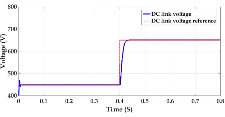
Response of the converter to a step change in output voltage from 450V to 650V is depicted in Fig.8. It is an important issue because in some cases the voltage of the DC link is not fixed [20]. It can be seen that the converter possesses a good response time (about 33mS).
Fig. 9 Shows a comparison between the power loss of the proposed converter and conventional converters dur-ing load current changes. The losses are calculated usdur-ing (6) and (7). The proposed converter power dissipation is always less than the conventional ones, especially in light loads. The loss reduction in full load is about 12% but in light loads it reaches to about 40% compared with con-ventional converter with EPDC. The reasons for this loss reduction are the lower voltage rating of switches and lower duty cycles. The lower voltage rating of the switch, the lesser on-state resistance of the switch. Furthermore, lower duty cycle results in lower conduction loss. The loss reduction in light loads is more than heavy loads. In fact the operation of the proposed converter in light load con-ditions such as urban driving has a superb advantage over the conventional interleaved DC-DC converter.
3. 2. Simulation of the Proposed Converter Within an FCV
The proposed converter is suitable for an FCV. There-fore, the performance of this converter should be investi-gated and compared to a conventional interleaved boost converter in a vehicle simulator software. ADVISOR is used to simulate the FCV in driving cycles. Then, the power profile demanded from the FC in the driving cycles is extracted from the ADVISOR and is applied as the load of the converter. Finally the losses of the converter in those drive cycles are calculated using (6) and (7). Fur-thermore the conventional converter with EPDC is simu-lated in the same drive cycles too. After that, one can compare the losses of the two converters which operate in same the conditions and the same control strategy.
As an urban drive cycle, the UDDS drive cycle is se-lected to simulate the FCV. Fig. 10 shows the vehicle speeds versus operating time for this driving cycle. By simulating the FCV in the mentioned driving cycle, the power demanded from the FC stack is shown in Fig. 11. This power profile is divided into three sections. In high power demands (highlighted in red) all four phases of the converter conduct the current. In middle power range
Fig. 8. Close-loop response of the output voltage to a step command
Fig. 9. Power dissipated by the proposed and conventional converters
Fig. 10. Speed-time characteristic of UDDS drive cycle
(highlighted in yellow), three phases participate in power supplying. In low output powers – which is most of the driving time in an urban driving cycle– only two phases of the converter, i.e., lower stage, is activated. This power section is highlighted in green in the power profile of Fig. 11.
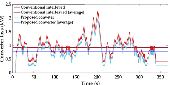
By applying the power demand profile extracted from driving simulation to the proposed converter and conven-tional converter, the converter power loss profile of Fig. 12 is obtained using (6) and (7).
In this figure, the red curve is the power dissipated in conventional interleaved converter during the driving cycle versus time. The blue curve is the power loss of the proposed converter. Furthermore, the average power losses of the conventional and proposed converter are de-picted. As it can be seen, the average power loss of the proposed converter in the simulated urban driving cycle is about 68% of the loss of the conventional converter. This is because of lower "off" state voltage of two switches of the proposed converter than conventional
con-verter switches. Furthermore, as mentioned before, the duty ratio of these two switches is also less than conven-tional one. Therefore, the conduction loss of the proposed converter is lower. Reducing the voltage stress of IGBTs may allow utilization of lower voltage rated IGBTs. De-creasing the voltage rating of the switches not only results into use of cheaper IGBTs, but also leads to smaller "on" state resistance i.e., lower rc. Therefore, the conduction loss is further reduced.
A similar simulation and comparison are done in a highway drive cycle (US06_HWY) to investigate the per-formance of the proposed converter in a high power de-mand operation. Fig. 13 depicts the speed-time characteristics of this cycle. As it can be seen the vehicle speed is more than its speed in UDDS Urban driving cycle.
Fig.14 illustrates the FC output power in this drive cycle. As it can be seen the operation of the converter in the red zone is more than an urban drive cycle. It means that the converter operates for longer periods with four
Fig. 11. FC output power in UDDS drive cycle
Fig. 12.Power losses of converters during UDDS cycle
legs. Fig. 15 depicts converter power losses when operat-ing in this drivoperat-ing situation. It is seen that even in high power demand operation the proposed converter has less power dissipation compared to conventional one. The converter average loss is reduced to 83% of the conven-tional interleaved converter.
Fig. 16 summarizes the simulation results. As it is seen, in both driving cycles, i.e., urban and highway, the proposed converter possesses lower power loss. However
the difference between the average power losses in high-way drive cycle is less than its counterpart in an urban drive cycle. This is because of this fact that as mentioned before, the proposed converter is more efficient in lighter load conditions. Because in light loads mostly two legs of the converter with lower voltage on their switches supply the power.
Vehicle
speed
(k
m
/
h
)
Fig. 13.Speed-time characteristic of US06_HWY
Fig. 14.FC output power in US06_HWY drive cycle
Con
v
er
ter
loss
(k
W
)
Fig. 15.Power losses of converters during US06_HWY cycle
4. Conclusion
In this paper, a novel DC-DC interleaved converter has been proposed. The steady-state characteristics of the con-verter were studied. Open-loop and close-loop behavior of the converter were investigated. Comparing to conven-tional interleaved converter, the proposed one has a lower switch voltage stress and lower duty cycle for its two switches. Therefore, the converter losses are reduced about 12% in full load and about 40% in light load con-ditions. Furthermore, the converter is simulated within an FCV by ADVISOR software in an urban and a highway drive cycles. In both drive cycles, the proposed converter seems more efficient than conventional interleaved con-verter which is used in existing FCVs such as TOYOTA MIRAI 2015. The results show that in urban drive cycle, the average losses of the converter are reduced about 32% compared to conventional converter. This reduction is about 17% in highway drive cycle. Therefore the pro-posed converter is more suitable for urban driving.
References
[1] A. Emadi and S. S. Williamson, "Fuel cell vehicles: opportunities and challenges," in IEEE Power En-gineering Society General Meeting, 2004., 2004, pp. 1640-1645 Vol.2.
[2] A. Khaligh and Z. Li, "Battery, Ultracapacitor, Fuel Cell, and Hybrid Energy Storage Systems for Electric, Hybrid Electric, Fuel Cell, and Plug-In Hybrid Electric Vehicles: State of the Art," IEEE Transactions on Vehicular Technology, vol. 59, pp. 2806-2814, 2010.
[3] C. Rayment and S. Sherwin, "Introduction to fuel cell technology," Department of Aerospace and Me-chanical Engineering, University of Notre Dame, Notre Dame, IN, vol. 46556, pp. 11-12, 2003. [4] O. Hegazy, J. Van Mierlo, and P. Lataire, "Analysis,
modeling, and implementation of a multidevice in-terleaved DC/DC converter for fuel cell hybrid
electric vehicles," IEEE transactions on power elec-tronics, vol. 27, pp. 4445-4458, 2012.
[5] J. Bauman and M. Kazerani, "A comparative study of fuel-cell–battery, fuel-cell–ultracapacitor, and fuel-cell–battery–ultracapacitor vehicles," IEEE Transactions on Vehicular Technology, vol. 57, pp. 760-769, 2008.
[6] A. Emadi, K. Rajashekara, S. S. Williamson, and S. M. Lukic, "Topological overview of hybrid elec-tric and fuel cell vehicular power system architec-tures and configurations," IEEE Transactions on Vehicular Technology, vol. 54, pp. 763-770, 2005. [7] W. Li, Y. Zhao, J. Wu, and X. He, "Interleaved high step-up converter with winding-cross-coupled in-ductors and voltage multiplier cells," IEEE trans-actions on power electronics, vol. 27, pp. 133-143, 2012.
[8] M. Khalilzadeh and K. Abbaszadeh, "Non-isolated high step-up DC–DC converter based on coupled inductor with reduced voltage stress," IET Power Electronics, vol. 8, pp. 2184-2194, 2015.
[9] M. Khalilzadeh, M. Mahdipour, and K. Ab-baszadeh, "High step-up DC-DC converter based on three-winding coupled inductor," in Power Elec-tronics, Drives Systems & Technologies Confer-ence (PEDSTC), 2015 6th, 2015, pp. 195-200. [10] C. M. Lai, C. T. Pan, and M. C. Cheng, "
High-effi-ciency modular high step-up interleaved boost con-verter for DC-microgrid applications," IEEE Transactions on Industry Applications, vol. 48, pp. 161-171, 2012.
[11] R. Ling, G. Zhao, and Q. Huang, "High step-up in-terleaved boost converter with low switch voltage stress," Electric Power Systems Research, vol. 128, pp. 11-18, 2015.
[12] K. C. Tseng, J. T. Lin, and C. C. Huang, "High step-up converter with three-winding costep-upled inductor for fuel cell energy source applications," IEEE 367
922
251
765
0 200 400
600
800 1000
Urbandriving Highwaydriving
Con
v
erter
a
v
era
g
e
loss
(
W
)
Driving cycles
ConventionalConverter ProposedConverter
Fig. 16. Comparison of the converters power loss
Transactions on Power Electronics, vol. 30, pp. 574-581, 2015.
[13] B. Wahdame, L. Girardot, D. Hissel, F. Harel, X. François, D. Candusso, et al., "Impact of power converter current ripple on the durability of a fuel cell stack," in Industrial Electronics, 2008. ISIE 2008. IEEE International Symposium on, 2008, pp. 1495-1500.
[14] W. Choi, P. Enjeti, J. W. Howze, and G. Joung, "An experimental evaluation of the effects of ripple cur-rent generated by the power conditioning stage on a proton exchange membrane fuel cell stack," Jour-nal of materials engineering and performance, vol. 13, pp. 257-264, 2004.
[15] M. Khalilzadeh and A. Fereidunian, "A Markovian approach applied to reliability modeling of bidirec-tional DC-DC converters used in PHEVs and smart grids," Iranian Journal of Electrical & Electronic Engineering, vol. 12, pp. 0-0, 2016.
[16] M. Nikzad and A. Radan, "Accurate loss modelling of fuel cell boost converter and traction inverter for efficiency calculation in fuel cell-battery hybrid ve-hicles," in Power Electronic & Drive Systems & Technologies Conference (PEDSTC), 2010 1st, 2010, pp. 218-223.
[17] D.Graovac, M.Pürschel, "IGBT Power Losses Cal-culation Using the Data-Sheet Parameters", Infi-neon Application Note, V 1. 1, January 2009. [18] Y. Hasuka, H. Sekine, K. Katano, and Y. Nonobe,
"Development of Boost Converter for MIRAI," SAE Technical Paper 0148-7191, 2015.
[19] M. Ehsani, Y. Gao, and A. Emadi, “Modern elec-tric, hybrid electric”, and fuel cell vehicles: funda-mentals, theory, and design: CRC press, 2009. [20] T. Schoenen, M. S. Kunter, M. D. Hennen, and R.
W. De Doncker, "Advantages of a variable dc-link voltage by using a dc-dc converter in hybrid-elec-tric vehicles," in Vehicle Power and Propulsion Conference (VPPC), 2010 IEEE, 2010, pp. 1-5.
Mohammad Khalilzadeh is a PhD Student in the University of Tehran, Tehran, Iran. He re-ceived his M.Sc. and B.Sc. in Electrical Engineering from K. N. Toosi University of Technol-ogy and the University of Tehran in 2012 and 2014 respectively. His research inter-ests include power electronic converters, reliability in power electronics, renewable energy, and electric motor drives.
Mohammad Reza Nikzad re-ceived the B.Sc and M.Sc de-grees from K. N. Toosi university of Technology both in power electrical engineering, in 2005 and 2008. Since 2011, he is pursuing his Ph.D. degree at University of Tehran, Tehran, Iran. His main re-search interests are in the areas of Electric, Electric Hybrid, and fuel cell vehicles, Power electronic converters Topology and Control, Power electronic converters Loss modeling, Electric motor drives, Battery and ultracapacitor energy storages and Soft switching techniques.
Behzad Asaei received his B.Sc. and M.Sc. degrees from the Uni-versity of Tehran in 1988 and 1990, respectively, and his Ph.D. degree from the Sydney Univer-sity in 1995, all in electrical en-gineering. From 1996 to 2006, he was with the Irankhodro Company Research and Development Center as Electrical Engineer Design Manager and doing research in automotive industry mainly on solar, electric and hybrid electric vehi-cles, while simultaneously he has been at the Uni-versity of Yazd as Assistant professor. Since 2006, he has been at the University of Tehran, school of Electrical and Computer Engineering, where he is an associate Professor and director of the Energy and Automotive Technology Lab. He was the vice president of the Mapfan Research Institute a joint institute between the University of Tehran and Mapna Group that is doing research in the fields of power generation, rail industry, and oil and gas in-dustry from 2010 to 2014. Since 1996, he was Managing director of several companies in the field of Automotive, and Energy Sectors. From 2014 he joined Mah-Taab group as Managing Director of Arian Mah-Baad Company that is an IPP in the field of renewable energy in several wind farms that are under construction and development with 3.2 and 3.4 MW Siemens PMDD Wind turbines. His research is focused in the field of automotive electronics, wind energy, solar energy, solar, elec-tric and hybrid elecelec-tric vehicles, power electronics, motor drives, and power generation in which sev-eral projects are completed.