Iranian Journal of Electrical and Electronic Engineering, Vol. 16, No. 1, March 2020 96
Multi-level Thrust Ripples Minimization of Linear Flux
Switching Motors With Segmented Secondary by Combined
Genetic Algorithm and Response Surface Methodology
M. S. Hosseini*, H. Javadi*(C.A.) and S. Vaez-Zadeh**
Abstract: Linear flux switching motors with simple passive segmented secondary, referred as Segmented Secondary Linear Flux Switching Motors (SSLFSMs), have low cost secondary and therefore are applicable to transportation systems like Maglev. However, it is shown that the SSLFSMs suffer from high thrust ripples. In this paper, minimizing SSLFSM thrust ripples besides maximizing its developed thrust are performed by considering the motor dimensions as design variables. Since the optimization of the motor is a high dimensional problem, a multi-level optimization method is employed to improve the machine performances and efficiency. According to the effects of the design variables on the optimization objectives, a sensitivity analysis is carried out to divide the design variables into two levels: mild-sensitive level and strong-sensitive level. Then, the two levels of design variables are optimized based on a mathematical model. Two different optimization methods as the Design of Experiment (DOE) and the Response Surface Method (RSM) are used in mild-sensitive level and the Genetic Algorithm (GA) is also used in strong-sensitive level. Based on FEM analysis, electromagnetic performance of the original motor and the optimal one are compared and the validity of the proposed optimization method is verified. Also, the effectiveness of the mathematical model used in thrust and thrust ripples calculations is evaluated and verified.
Keywords: Linear flux Switching Motors, Multi-Level Optimization, Response Surface Methodology, Sensitivity Analysis Method, Thrust Ripples Minimization.
1 Introduction1
INEAR Flux Switching Motors (LFSMs) inherit most merits of rotary Flux Switching Motors (FSMs) that leads to simple and robust structure of secondary and high force density [1-2]. When the stator is very long, e.g. in the case of Maglev or underground train drives, such a simple and low cost secondary is
Iranian Journal of Electrical and Electronic Engineering, 2019. Paper first received 27 June 2018, revised 20 May 2019, and accepted 24 May 2019.
* The authors are with the School of Electrical Engineering, College of Engineering, Shahid Beheshti University, Tehran, Iran.
E-mails: [email protected] and [email protected].
** The author is with the Center of Excellence on Applied Electromagnetic Systems and the Advanced Motion Systems Research Lab, School of Electrical & Computer Engineering, College of Engineering, University of Tehran, Tehran, Iran.
E-mail: [email protected].
Corresponding Author: H. Javadi.
attractive. Recently, a LFSM with a novel structure, referred as Segmented Secondary Linear Flux Switching Motor (SSLFSM), is introduced for rail transportation systems [3]. In such a structure, the armature and field windings are wounded in the primary slots and the secondary is composed of simple laminated segments. The power supply for DC excitation can be placed on the mover and the AC currents of armature windings can be drawn from transmission lines above the train and along the track. Bi-polar flux linkage [4] leading to high force density and close to sinusoidal back-emf facilitating less complicated control strategy [5-6] are other advantages of FSMs that are inherited to SSLFSM. Improved sinusoidal back-emf of SSLFSMs is achieved by some modifications into their structure [7]. Nevertheless, it has higher thrust ripples caused by the segmented structure of secondary that should be minimized. A d-q model representation of SSLFSMs is achieved based on Finite Element Method (FEM) [8]
L
Iranian Journal of Electrical and Electronic Engineering, Vol. 16, No. 1, March 2020 97
but thrust ripples calculation is not presented.
Optimizing average thrust of different types of linear flux switching motors are studied based on FEM [9-10]. Cogging torque reduction of rotary flux switching motors [11-13] beside its average torque improvement [12-13] are studied by FEM analysis too. However, the FEM-based method is time consuming and needs intensive computations. Thrust [14] and thrust ripple minimization [15] of LSMs based on an analytical layer modeling are studied in the literature. Layer modeling is fast against FEM-based modeling, but it is less accurate especially in the case of motors with high saliency in primary and secondary as SSLFSMs.
Here a mathematical model to calculate the motor thrust and thrust ripples is recalled [16]. This mathematical model is necessary for design optimization of the newly developed SSLFSMs and is fast and accurate enough in comparison with FEM-based and layer modeling methods. Besides, minimizing the thrust ripples (which is the main aim of this paper) and maximizing average thrust, which is very important in propulsion systems are other objectives of the optimization problem. As a result, a dual-objective optimization is carried out. The motor dimensions are considered as design variables. According to the effect of the design variables on the optimization objectives, sensitivity analysis method is used to divide the design variables into two levels: mild-sensitive level and strong-sensitive level. Multi-level optimization procedure is effective in the case of high dimensional optimization problems [12-13], [17]. By appropriate braking of the problem into different levels, the optimization time and accuracy will be improved. Sensitivity analysis is a common method in dividing the optimization levels [12-13, 17]
.
Since SSLFSM is a new motor, its optimization is absent in the literature. In this paper, it is tried to improve machine characteristics. Also, multi-level optimization for this motor is done for the first time. In addition, the analysis method beside the multilevel optimization of the SSLFSM is novel and can be applied to other motors. Also, the newly developed machine model [16] is adapted to the multi-level sensitive analysis based optimization procedure in this paper.
Different sections of the paper are as following. Motor topology and its 2D analytical model are presented in Section 2. The machine are divided into different regions and an exact solution is obtained for each region by solving Maxwell and Poison equations. Optimization problem considering the developed thrust and thrust ripples as optimization objectives and different dimensions of the motor as design variables, are defined in Section 3. Then, the design optimization of the motor based on the analytical model is carried out in Section 4. Sensitivity analysis is performed to divide the design variables into two levels: mild-sensitive level and
strong-sensitive level. The Design of Experiment (DOE) and the Response Surface Method (RSM) is used as optimization method in mild-sensitive level and Genetic Algorithm (GA) in strong-sensitive level. Design evaluation based on a finite element analysis is carried out in Section 5. The effectiveness of the mathematical model used in thrust and thrust ripples calculations and the validity of the proposed optimization method are studied. Finally, some conclusions are presented in Section 6.
2 Machine Model
2.1 MotorTopology and Operation Principles
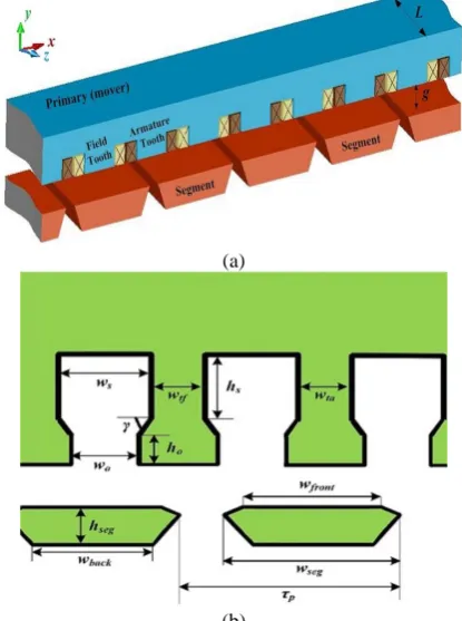
Fig. 1 shows a schematic view of a single-sided SSLFSM with a long secondary [18]. The primary, which is the mover of the motor, includes both three-phase winding coils and DC excitation field coils alternatively. The polarization of each excitation winding is opposite to the next one. The secondary of SSLFSM is composed of simple segments which makes this topology applicable to rail transportation systems. DC windings and secondary segmentsconstitute electromagnetic poles. When the mover moves along the secondary and the field coils are excited, the polarity of the armature winding flux linkage changes as well as its value. This bipolar flux linkage induces a sinusoidal back-emf in the armature coils.Nevertheless, salient structure of the motor primary and secondary causes the
(a)
(b)
Fig. 1 Parameters and dimensions of the SSLFSM. a) 3-dimensional view of the motor and b) 2-dimensional view
of the motor illustrating detailed structure of segments and primary teeth.
Iranian Journal of Electrical and Electronic Engineering, Vol. 16, No. 1, March 2020 98
generation of undesirable thrust ripples.
The parameters and dimensions of the motor are as follow: L is the motor width along the z direction, g is the airgap length, τp is twice the motor pole pitch, which
is the distance between one segment to the next one,
wseg is the segment width, wfront is the segment front part
width, which is in front of air gap, wback is the segment
back part width, which lies on the track, hseg is the
segment height, ws is the slot width, hs is the slot height,
wo is the slot opening width, ho is the slot opening
height, wtf is the field tooth width, wta is the armature
tooth width, γ is the tooth tip angle.
2.2 Analytical Model [16]
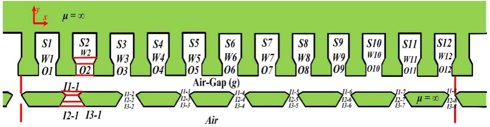
In this subsection a method of developing an analytical model for the SSLFSM is briefly explained [19]. The method is based on solving Maxwell and Poison equations in certain regions of the motor shown in Fig. 2. It is known that the magnetic flux density (B) in each region can be written as:
B A (1)
where A is the magnetic vector potential. The magnetostatic Maxwell equations lead to a Poisson equation, given by:
2
0 r
A J
(2)
where μr is the relative permeability of each region.
Since the current density vector J has only a component in the z-direction, A also has a component in z-direction, therefore, Eq. (2) reduces to:
2 2 0 2 2 , , z z r zA x y A x y
J
x y
(3)
In order to solve (3) in the 12 slot regions, it is necessary to describe current sources in term of Fourier series. Current source description is obtained by applying the imaging method [19] as:
0 1
i i si s si ci s si
n
J J J sin x J cos x
(4)
2 1 2 0 0 2 0 2 0 1 2 1 2 2 1 0 1 2 1 2 s s s i ii i si
s
si i s si si
s
ci i s si si
s
n
i i
J J
J J dx
J n J sin x dx
J n J cos x dx
n
sin J J
n
(5)where J1i and J2i are current density of half area in i-th
slot in term of A/m2, τ
s is the width of the slot regions,
S1-S12, and ωs is the spatial frequency of the region
given by:
s s n n (6)The solution for the magnetic vector potential is written in terms of Fourier components as the following:
0 1 ˆ ˆ , z ks k k c k k
n
A A x y z
A y A y sin x A y cos x z
(7)where ωk is the spatial frequency of the region k,
defined as: k k n (8)
Hence, the expressions for the magnetic flux density distribution in different regions are given as:
0 1 1 ˆ ˆxs k k xc k k x
n
ys k k yc k k
n
B B y sin x B y cos x B y x
B y sin x B y cos x y
(9)where the functions Bxs, Bxc, Bx0, Bys and Byc can be
obtained by considering the transfer relations for every coordinate system [19] and are given by:
0 0 0
k k
k k
k k
k k
y y c
ys n n
k
y y s
yc n n
k
y y
xs n n
y y
xc n n
x
J
B a e b e
J
B c e d e
B c e d e
B a e b e
B J y B
(10)
The set of unknowns an, bn, cn, dn, and B0 for every
region is obtained by solving (10), considering the Neumann and continuous boundary conditions in the y -direction. As a result, the normal component of flux density at y=y0 in the airgap is given by (11):
1 , g g g g g n y yy g g n g n g
n
y y
g g n g n g
B x y sin x a e b e
cos x c e d e
(11)where ωg is the spatial frequency of the region g, ng is
the number of harmonics in region g.
3.3 Thrust and Thrust Ripples Calculations
In order to calculate the motor thrust, virtual work method is employed, while for the sake of
Iranian Journal of Electrical and Electronic Engineering, Vol. 16, No. 1, March 2020 99 Fig. 2 Different regions of the SSLFSM.
simplification, the stored electromagnetic energy in the iron part of the motor is considered unchanged. Electromagnetic energy stored in the airgap (W(x,y)) is
calculated for different positions of the motor as (12) [20]:
2
0
0
, ,
2
M x y
x
B x y
W x y L g dx
(12)where M is the primary total length and By(x,y) is the
airgap flux density produced by both field excitation and armature currents in different positions of x and y. Differential variation of energy along the x direction equals to the detent force obtained as (13):
2
0
0 , ,
2
M x y
x
B x y
dW x y d
F x L g dx
dx dx
(13)It should be mentioned that in the case of small airgap, the flux density variation in the airgap along y axis is not considerable. Therefore, middle of the airgapy=g/2 is assumed as a reference point. Thrust ripple equation is as (14):
100 2
max min
ave
F F
Thrust ripple
F
(14)
In this analysis thrust ripples caused by salient structure of the motor is considered, whereas the end effect related force ripples are ignored. Has been shown that, the end effect of the motor is negligible and independent of its moving speed [8]. This is due to the fact that the airgap flux density in the case of short primary with end teeth or long primary are the same [8].
3 Optimization Problem
An optimization problem with p objectives, n
variables, and m constraints is formulated as:
1 2
Maximize f x , f x ,, fp(x), xK (15)
where x∈ Rn, f: Rn→R. Also, K is a feasible set of
solution (15) which is described by (16):
R : n 0, 1, 2, ,
i
K x g x i p (16)
where gi(x) are optimization constraints which limit the
design variables. The design variables are chosen as segment height, segment factor (sf) defined as wseg/τp,
segment back factor (sbf), defined as wback/wseg, Segment
Chamfer Length Ratio (SCLR), defined as wfront/wseg,
field tooth width, armature tooth width, slot width, slot height, slot opening width, slot opening height, and tooth tip angle based on their important influence on the design optimization as considered later in this section. The design objectives in this paper are to maximize the motor developed thrust and minimize its thrust ripples. A 12/8 SSLFSM of the type depicted in Fig. 1 is selected as the basis for optimization. Figs. 3-5 show the variations of objective functions in terms of motor dimensions. Figs. 3(a) and (b) show variations of motor average thrust and thrust ripples in terms of armature and field teeth widths, respectively, when the other motor variables are constant. As it is seen, both objectives increase with an increase in the armature tooth width. Also, field tooth width has a strong effect on both the motor average thrust and thrust ripples. It can be seen that the objectives do not have simple common optimal point as far as teeth widths are concerned. Therefore, both design variables should be considered in the optimization procedure. Figs. 3(c) and (d) show variations of the motor average thrust and thrust ripples in terms of slot width and height. It is seen that the motor average thrust increases and its thrust ripples decrease with a decrease in the slot height. Therefore, to maximize the developed thrust of the motor and minimize its ripples, the slot height should be set to its minimum value. However, changes in slot width strongly affects both objectives, but it does not have specific rhythm. Therefore, the design variables of slot width should be considered in the optimization procedure to find the optimal point. Figs. 4(a) -(d) show variations of two objectives in terms of slot opening width and height, segment back factor and segment height, respectively. It is seen that the motor thrust ripples increase with an increase in slot opening height and its average thrust decreases with an increase in segment back factor. As it is seen in Figs. 4(a) -(d), the
Iranian Journal of Electrical and Electronic Engineering, Vol. 16, No. 1, March 2020 100
(a) (b)
(c) (d)
Fig. 3 Thrust and thrust ripples variations in terms of a) armature and b) field teeth widths, and c) slot width and d) height.
(a) (b)
(c) (d)
Fig. 4 Thrust and thrust ripples variations in terms of a) slot opening width and b) height, and c) segment back factor and d) segment height.
four variables of slot opening width and height, segment back factor and segment height strongly affect the two objectives but without any specific rule. As a result, to find the optimal point of the optimization problem, it is necessary to consider these design variables as optimization variables.
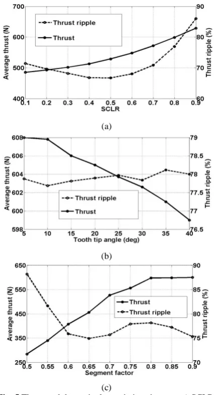
The motor average thrust and thrust ripples variations in terms of SCLR, tooth tip angle and decrease in tooth tip angle and an increase in segment factor, leads to an increase in the motor segment factor are shown in Figs. 5(a)-(c), respectively. It is seen that an increase in SCLR, an average thrust. However, changes in these
Iranian Journal of Electrical and Electronic Engineering, Vol. 16, No. 1, March 2020 101
three design variables do not lead to a certain variation in the motor thrust ripples. Therefore, these design variables should also be taken into account in the optimization procedure. In order to prevent unrealistic optimization results, some constraints are applied to the design variables which are presented in Table 1. As it can be seen a minimum and a maximum value are assigned for each design variable.
(a)
(b)
(c)
Fig. 5 Thrust and thrust ripples variations in terms a) SCLR, b) tooth tip angle, and c) segment factor.
Table 1 Design constraint.
Parameter Unit Symbol Min Max
Field tooth width mm wtf 14 50
Armature tooth width mm wta 13 20
Slot width mm ws 14 23
Slot height mm ws 40 75
Slot opening width mm wso 8 16
Slot opening height mm wso 1 9
Segment height mm hs 12 20
Segment back-factor - wse 0.4 1.2
Segment factor - wse 0.5 0.9
Tooth tip angle deg hm 5 40
SCLR - SCLR 0.1 0.9
4 Design Optimization
Since the optimization problem is a high dimensional one, a two-level optimization method is efficient to improve the performances as well as the optimization efficiency. Two-level optimization method leads to more accuracy and less computational time. So, in this section, a sensitivity method is adopted and two level design variables are defined: mild-sensitive level and strong-sensitive level. Then, to improve the whole design efficiency, the DOE &RSM and GA are applied in the mild-sensitive level and strong-sensitive level, respectively. Also, other optimization method can be used but here DOE & RSM and GA methods are chosen [12]. Fig. 6 shows the flowchart of the total optimization process.
4.1 Sensitivity Analysis Method
In order to break a large scale optimization problem into small parts, it is necessary to evaluate each design variable effect on the optimization objectives individually and independently. To achieve this, sensitive analysis method is useful and effective. In this
Fig. 6 The total flowchart of optimization procedure.
Iranian Journal of Electrical and Electronic Engineering, Vol. 16, No. 1, March 2020 102
way a sensitivity index (H(xi)) considering constraints
of Table 1 is chosen for each design variable as following [13]:
/ i
iV E y x H x
V y
(17)
where xi is the design variable, y is optimization
objectives, E(y/xi) is the average value of y when xi is
constant at its initial value and other design variables changes from their minimum value to their maximum value, V(E(y,xi)) is the variance of E(y,xi), and V(y) is
variance of y. Since there are two optimization objectives, a comprehensive sensitivity function S(xi)
which combines the sensitivity of two objectives into a single one is introduced as following [12], [13]:
i 1 thrust
i 2 ripple
iS x H x H x (18)
where λ1 and λ2 are the weight coefficients of the
developed thrust and thrust ripples, which satisfy the equation λ1+λ2=1; Hthrust(xi) and Hripple(xi) are the
sensitivity indices of the two objectives. Since the importance of the two optimization objectives in this paper are the same, λ1 and λ2 are set to 0.5. Then the
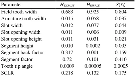
sensitivity function of each design variable is easily obtained from Eqs. (17) and (18). Table 2 illustrates the sensitivity indices and the comprehensive sensitivity function values for each design variable. In the case of selecting a separating condition at S(xi)=0.04, half of
the design variables have comprehensive sensitivity function value more than this threshold and the other half have comprehensive sensitivity function value less than 0.04. Therefore, the separating condition is chosen considering comprehensive sensitivity function value for different design variables. In the case of S(xi)>0.04,
the design variable of xi is optimized in strong sensitive
level (i.e. level 1) and otherwise is optimized in the mild-sensitive level ( i.e. level 2). In this way the design variables are classified into two different groups and consequently the initial optimization problem is broken into two smaller problems.
4.2 GA in Strong-Sensitive Level Optimization
Considering the results of the sensitivity function presented in Table 2, S(xi) is bigger than 0.04 for design
variables of field tooth width, slot width, segment back factor, segment factor and SCLR. Therefore, these five variables are selected to be optimized in the strong-sensitive level. GA is chosen as optimization algorithm of this level. Since there are two optimization objectives, a weighted function with the same importance for each objective is employed as following [21]:
0.5 0.5 thrust
ripple
f f
f
(19)
Table 2 Sensitivity indices of optimization objectives. Parameter HTHRUST HRIPPLE S(XI)
Field tooth width 0.683 0.925 0.804 Armature tooth width 0.015 0.058 0.037
Slot width 0.012 0.077 0.044
Slot opening width 0.011 0.006 0.009 Slot opening height 0.011 0.031 0.021
Segment height 0.010 0.0002 0.005
Segment back-factor 0.317 0.001 0.159
Segment factor 0.72 0.101 0.410
Tooth tip angle 0.0009 0.00005 0.0005
SCLR 0.218 0.132 0.175
Therefore maximizing the function f is the single optimization objective of the GA. Since the weight of each objective (thrust and thrust ripple) are the same at 0.5, the algorithm tends to optimize them in the same order [21]. In order to achieve to the optimal point, an initial population with 25 population size is randomly produced. The best answer of this population is directly transferred to the next generation. Selection, crossover and mutation as main operators of GA are used to produce other answers of each generation.
In this paper, the selection operator employs the Tournament and the Roulette wheel methods with equal probabilities and the probability for the crossover and mutation operators equal 0.93 and 0.07, respectively [22]. It should be mentioned that 40 iterations are carried out to reach the optimal point step by step.
4.3 DOE and RSM in Mild-Sensitive Level
Optimization
Considering the results of sensitivity analysis presented in Table 2, S(xi) is less than 0.04 for design
variables of armature tooth width, slot opening width, slot opening height, segment height and tooth tip angle which are respectively coded as X1, X2, X3, X4 and X5.
So, these variables have less effect on optimization objectives compared to other variables. As a result they are considered as a group to be optimized in mild-sensitive level. In this level DOE and RSM are chosen as optimization methodology. The value of each design variable is normalized in interval of [-1, 1]. The two objectives of maximizing the motor average thrust and minimizing its thrust ripples are coded as Y1 and Y2
respectively. It is tried to find the RSM common second order models for Y1 and Y2 in terms of X1-X5 as
following [23]:
Yi = αi+ βiX1 + γiX2 + δiX3 + εiX4 + ζiX5 +
ηiX1X1 + νiX2X2 + ξiX3X3 + ρiX4X4 + ςiX5X5 +
σiX1X2 + χiX1X3 + υiX1X4 + ϝiX1X5 + ϨiX2X3 + ϬiX2
X4 + ϱiX2X5 for i = 1, 2 (20)
To achieve this, a DOE with a 25-2=8 fractional
factorial Central Composite Design (CCD) is
Iranian Journal of Electrical and Electronic Engineering, Vol. 16, No. 1, March 2020 103
employed [24]. Also, 4 center points of (0,0,0,0,0), and 10 axial points of (±1,0,0,0,0), (0,±1,0,0,0), … and (0,0,0,0,±1) are selected. Totally, the results of 22 runs are presented in Table 3. Then, the coefficients of the second order models of (10) are obtained with Minitab Software. These results are presented in Table 4. In order to solve a two-objective (Y1 and Y2) problem, a
weighted additive Goal Programming (GP) method is employed as (21) and (22):
2
1
max j j
j
Z w
(21)
0.50,1 for 1, 2
j j j j Y w j (22)
where αi and wi denote the achievement degree and the
weight of j-th goal, respectively. The µY1 and µY2 are
membership functions of the two objectives that are respectively given as (23) and (24). These functions are obtained based on the results of a pay-off table of a Positive Ideal Solution (PIS) as presented in Table 5 [10].
1 1 1 1 1 0 0.54 0.54
0.54 1.02
1.02 0.54 1 1.02 Y Y Y Y Y (23)
Table 3 Results of the RSM experiments. Input Variables Output Variables
Run X1 X2 X3 X4 X5 Y1 Y2
1 -1 1 1 -1 -1 0.790 0.500
2 0 0 0 -1 0 0.878 0.646
3 -1 0 0 0 0 0.815 0.568
4 1 -1 -1 -1 -1 0.841 0.720
5 0 0 0 0 0 0.926 0.750
6 -1 1 -1 -1 1 0.833 0.510
7 0 0 0 0 0 0.926 0.750
8 0 0 0 0 -1 0.930 0.768
9 0 -1 0 0 0 0.844 0.646
10 1 0 0 0 0 0.981 0.594
11 1 -1 1 -1 1 0.766 0.454
12 1 1 1 1 1 0.981 0.565
13 0 1 0 0 0 0.943 0.842
14 1 1 -1 1 -1 1 0.599
15 0 0 0 1 0 0.921 0.732
16 -1 -1 1 1 -1 0.666 0.451
17 0 0 1 0 0 0.886 0.732
18 0 0 0 0 1 0.919 0.76
19 -1 -1 -1 1 1 0.799 0.653
20 0 0 0 0 0 0.926 0.750
21 0 0 -1 0 0 0.910 1
22 0 0 0 0 0 0.926 0.750
2 2 2 2 2 0 0.91 0.91
0.91 1.04
1.04 0.91 1 1.04 Y Y Y Y Y (24)
The presented model is solved with Lingo software and the optimal point of the mild-sensitive level is obtained. The optimization results for the SSLFSM considering all design variables in strong-sensitive level or in mild-sensitive level, are presented in Table 6 and are compared with the initial quantity values of motor. As it is seen, the motor average thrust is increased considerably from 599N to 1064N and its thrust ripples is reduced from 78% to 9.6%.
5 Design Evaluation
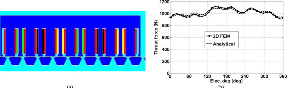
The design optimizations in level 1 and 2 of this work were carried out based on the analytical machine model presented in section II. So it is necessary to evaluate the model accuracy. A 2D finite element analysis is employed to evaluate the presented model. Fig. 7(a) shows the FEM model for the initial SSLFSM. Fig. 7(b) illustrates and compares thrust and thrust ripples obtained from the analytical model and 2D FEM analysis for the initial motor. These results are numerically compared in Table 6 which can be seen, the initial motor average thrust obtained from 2D FEM and the analytical model is respectively 578.5N and 599N, i.e. with 3.54% error. Also, thrust ripples obtained from 2D FEM analysis and the analytical model are respectively 77.6% and 78% with 0.52% difference. Therefore, there is good agreement between the analytical model and FEM analysis results both in the values and the shapes development.
Fig. 8(a) shows the FEM model for the optimized motor. Compared to the initial motor, the segments and the teeth dimensions have been totally changed. This optimization leads to a very smoother and stronger motor thrust. Fig. 8(b) illustrates and compares thrust and thrust ripples of the optimized motor obtained from the analytical model and 2D FEM. The optimized motor
Table 4 RSM second order model coefficients for Y1 and Y2. Coefficient i=1 i=2 Coefficient i=1 i=2
αi 0.9252 0.7632 ρi -0.0254 -0.0809
βi 0.0831 0.0131 ςi -0.0001 -0.0056
χi 0.0495 0.0979 σi 0.0052 -0.0327
δi -0.0324 -0.1341 χi 0.0159 -0.0069
εi 0.0219 0.0431 υi 0.0169 -0.111
ζi -0.0057 -0.0041 ϝi -0.0012 0.0701
ηi -0.0271 -0.1887 Ϩi 0.0182 0.0529
νi -0.0314 -0.026 Ϭi -0.0204 0.0147
ξi -0.0068 0.0962 ϱi -0.0042 0.005
Table 5 Pay-off table of PIS.
Y1 Y2
Max Y1 1.02 0.54
Max Y2 0.91 1.04
Iranian Journal of Electrical and Electronic Engineering, Vol. 16, No. 1, March 2020 104 Table 6 Design variables and objective values for the optimized motor.
Design Variables
Parameter [unit] Initial Motor Optimized Motor
Field tooth width [mm] 15 38
Armature tooth width [mm] 15 16
Slot width [mm] 20 16
Slot height [mm] 70 40
Slot opening width [mm] 14 9
Slot opening height [mm] 7 2.5
Segment height [mm] 18 13
Segment back-factor 0.62 0.5
Segment factor 0.8 0.9
Tooth tip angle [deg] 35 23
SCLR 0.8 0.75
Objective Values
Average thrust [N] Analytical 599 1064
2D FEM 578.5 1017
Thrust-ripples [%] Analytical 78 9.6
2D FEM 77.6 9.8
(a) (b)
Fig. 7 Initial motor modeled by 2D FEM a) motor structure and b) thrust force waveform.
(a) (b)
Fig. 8 Optimized motor modeled by 2D FEM a) motor structure and b) thrust force waveform.
average thrust obtained by 2D FEM and the analytical model are 1017N and 1064N, respectively. So, the 4.62% error has been only occurred. Thrust ripples of the optimized motor, obtained from 2D FEM and the analytical model are respectively, 9.8% and 9.6% with 2.04% error. As a result, a good agreement between the analytical model and FEM analysis results is achieved,
so it can be declared the effectiveness as well as the accuracy of the analytical model is verified too.
Now, considering the volume density of the iron weight as 7.86×10⁴N/m3, the weight of the segmented
secondary of the motor, which is lied along the rail are reduced from 92.45 N/m (9.245 kg) to 69.8 N/m (6.98 kg). This means 24.5% improvement (decrease) in
Iranian Journal of Electrical and Electronic Engineering, Vol. 16, No. 1, March 2020 105
considering the volume density of the copper weight as 9.8×10⁴N/m3, the weight of the primary of the motor is
increased from 332.5N (33.25 kg) to 357.8N (35.78 kg), i.e. 7.6%. Since the primary is a short type and considering the very good improvement in motor thrust and thrust ripples and material consumption in the segmented secondary, this increase is negligible. Considering the motor secondary only along its primary, the initial motor weight is 37.27 kg while the optimized motor weight is changed to 38.78 kg, i.e. 4% only increase in motor weight where the average ripple is increased 76% and the thrust ripple decreased sharply in comparing to initial motor.
6 Conclusion
A multi-level two-objective design optimization is performed on a SSLFSM to achieve high developed thrust and reduced thrust ripples. The motor dimensions are considered as design variables. According to the effect of the design variables on the optimization objectives, sensitivity analysis method is used to divide the design variables into two levels: as the mild-sensitive level and strong-mild-sensitive level. Then, the two levels of design variables are optimized based on a mathematical model. The mathematical model is obtained by solving Maxwell and Poison equations in certain regions of the motor and then, an analytical model is proposed for calculation of thrust and thrust ripples. Two different optimization methods are used; DOE and RSM in mild-sensitive level and GA in strong-sensitive level. As a result, dimensions of the optimized motor are carried out. 75.8% development in thrust and 87.4% development in thrust ripples are achieved. Also, the weight of the segmented secondary of the motor, which is lied along the rail are reduced from 92.45 N/m to 69.8 N/m with 24.5% improvement in rail material consumption. However, the weight of the primary of the motor is increased from 332.5N to 357.8N, i.e. 7.6%, but the primary is a short type and also considering the very good improvement in motor thrust and thrust ripples, this increase is negligible. A finite element analysis is employed to verify the mathematical modeling and optimization results. The accuracy of the mathematical model in thrust and thrust ripples calculations is verified with errors less than 5%. Finally, the effectiveness of the analytical modeling and the proposed optimization method is verified.
Acknowledgements
This work was supported by ALBORZ Province Power Distribution Company.
References
[1] C. C. Hwang, P. L. Li, and C.T. Liu, “Design and analysis of a novel hybrid excited linear flux switching permanent magnet motor,” IEEE Transaction on Magnetics, Vol. 48, No. 11, pp. 2969–2972, 2012.
“A linear doubly salient permanent magnet motor with modular and complementary structure,” IEEE Transaction on Magnetics, Vol. 47 No. 12, pp. 4809–4821, 2011.
[3] S. E. Abdollahi and S. Vaez-Zadeh, “Analysis of a novel linear flux switching motor with segmented secondary,” IEEE Transaction on Magnetics,
Vol. 50, No. 4, pp. 1–9, 2014.
[4] W. Hua, Z. Q. Zhu, M. Cheng, Y. Pang, and D. Howe, “Comparison of flux switching and doubly salient permanent magnet brushless machines,” in International Conference on Electrical Machines and Systems, China, Vol. 1, pp. 165–170, 2005.
[5] R. Cao, M. Cheng, and C. C. Mi, “Influence of leading design parameters on the force performance of a complementary and modular linear flux switching permanent magnet motor,” IEEE Transaction on Industrial Electronics, Vol. 61, No. 5, pp. 2165–2175, 2014.
[6] A. Zulu, B. C. Mecrow, and M. Armstrong, “Investigation of the dq-equivalent model for performance prediction of flux-switching synchronous motors with segmented rotors,” IEEE Transaction on Industrial Electronics, Vol. 59, No. 6, pp. 2393–2402, 2012.
[7] S. E. Abdollahi and S. Vaez-Zadeh, “Back-EMF analysis of a novel linear flux switching motor with segmented secondary,” IEEE Transaction on Magnetics, Vol. 50, No. 4,pp. 1–9, 2014.
[8] M. S. Hosseini, H. Javadi, S. Vaez-Zadeh, and S. E. Abdollahi, “Precise dq Model Development of Linear Flux Switching Motors with Segmented Secondary for Rail Transportation Applications,”
IET Electric Power Application, Vol. 12, No. 2, pp. 213–221, 2018.
[9] B. Zhang, M. Cheng, J. Wang, and S. Zhu, “Optimization and analysis of a yokeless linear flux-switching permanent magnet machine with high thrust density,” IEEE Transaction on Magnetics, Vol. 51, No. 11, pp. 1–4, 2015.
[10]B. Zhang, M. Cheng, R. Cao, Y. Du, and G. Zhang, “Analysis of linear flux switching permanent magnet motor using response surface methodology,” IEEE Transaction on Magnetics, Vol. 50, No. 11, 2014. [11]S. E. Abdollahi and S. Vaez-Zadeh, “Reducing
Cogging torque in flux switching motors with segmented rotor,” IEEE Transaction on Magnetics, Vol. 49, No. 10, pp. 5304–5309, 2013.
[12]Z. Xiang, X. Zhu, L. Quan, Y. Du, C. Zhang, and D. Fan, “Multilevel design optimization and operation of a brushless double mechanical port flux switching permanent magnet motor,” IEEE Transaction on Industrial Electronics, Vol. 63, No. 10, pp. 6042–6054, 2016.
Iranian Journal of Electrical and Electronic Engineering, Vol. 16, No. 1, March 2020 106
[13]X. Zhu, Z. Shu, L. Quan, Z. Xiang, and X. Pan, “Multi-objective optimization of an outer-rotor V-shaped permanent magnet flux switching motor based on multi-level design method,” IEEE Transaction on Magnetics, Vol. 52, No. 10, 2016. [14]S. Vaez-Zadeh and M. S. Hosseini, “Design
optimization of linear synchronous motors for overall improvement of thrust, efficiency, power factor and material consumption,” Journal of Power Electronics (JPE), Vol. 11, No. 1, pp. 105–111, 2011.
[15]M. S. Hosseini, M. M. Khameneh and S. Vaez-Zadeh, “Design of thrust ripple minimization in wound secondary linear synchronous motors by Response Surface Methodology (RSM),” Power Electronics Drive Systems and Technologies Conference (PEDSTC-2011), Tehran, 2011.
[16] M. S. Hosseini, H. Javadi, and S. Vaez-Zadeh, “Electromagnetic fields and thrust-ripples calculation for segmented-secondary linear flux-switching motors,” COMPEL–The International Journal for Computation and Mathematics in Electrical and Electronic Engineering, Vol. 38, No. 1, pp. 95–118, Jan. 2019.
[17]G. Lei, C. Liu, J. Zhu, and Y. Guo, “Techniques for multilevel design optimization of permanent magnet motors,” IEEE Transaction on Energy Conversion,
Vol. 30 No. 4, pp. 1574–1584, 2015.
[18]S. E. Abdollahi, “Design and optimization of linear flux switching motor with segmented secondary,”
Ph.D. Dissertation, Department of Electrical Engineering, Tehran Univiversity, Tehran, Iran, 2014.
[19]B. L. J. Gysen, K. J. Meessen, J. J. H. Paulides, and E. A. Lomonova, “General formulation of the electromagnetic field distribution in machines and devices using Fourier analysis,” IEEE Transactions on Magnetics, Vol. 46, No. 1, pp. 39–52, 2010. [20]D. K. Cheng, Field and wave Electromagnetics.
Addison-Wesley Press, 1989.
[21]G. Liuzzi, S. Lucidi, F. Parasiliti, and M. Villani, “Multiobjective optimization techniques for the design of induction motors,” IEEE Transactions on Magnetics, Vol. 39, No. 3, pp. 1261–1264, May 2003.
[22]N. Bianchi and S. Bolognani, “Design optimization of electric motors by genetic algorithm,” IEE Proceedings-Electric Power Applications, Vol. 145, No. 5, pp. 475–483, 1998.
[23]A. A. Najafi, S. T. AkhavanNiaki, and M. Shasavar, “A parameter tuned Genetic Algorithm for the response investment problem with discounted cash flows and generalized precedence relations,”
Elsevier Transaction on Computers and Operation Research, Vol. 36, No. 11, pp. 2994–3001, 2009. [24]R. H. Myers and D. C. Montgomery, Response
surface methodology: Process and product optimization using designed experiments. John Wiley & Sons, 1995.
M. S. Hosseini received the B.Sc. and M.Sc. degrees in Electrical Engineering both from the School of Electrical and Computer Engineering, University of Tehran, Tehran, Iran, in 2005 and 2009 respectively. She is currently working toward the Ph.D. degree in Electrical Engineering in the School of Electrical Engineering, University of Shahid Beheshti, Tehran, Iran. Her research interests include design, modeling, and optimization of electrical machines and electromagnetic studies. She is also reviewer of IEEE Transactions on Magnetics, IEEE Transactions on Energy Conversion, IEEE Transactions on Vehicular Technology, IET Electric Power Applications and so on.
H. Javadi received his B.Sc. in Electrical Engineering from Sharif University of Technology (Iran) in 1980, his Master from UMIST (UK) in 1986, and his Ph.D. degree in 1994 from the INPT (France), then, he joined to Electrical Engineering department of Power and Water University of Technology (which is currently joined to Shahid Beheshti University (SBU)). He is currently an Associate Professor and is expert in the area of insulation and high voltage technology, electrical machines and as well as power system studies.
S. Vaez-Zadeh has been with the University of Tehran, since 1997. His research interests include renewable energy, electrical drives, contactless power transfer, and energy policy. He has co-authored more than 150 technical papers and holds one US patent. He is the author of Control of Permanent Magnet Synchronous Motors, OXFORD University Press, 2018. Professor Vaez-Zadeh is an Editor of IEEE Transactions on Energy Conversion and a Subject Editor of IET Renewable Power Generation. He has been active in IEEE sponsored conferences as the General Chair and Keynote Speaker, and received several awards for his technical contributions.
© 2019 by the authors. Licensee IUST, Tehran, Iran. This article is an open access article distributed under the terms and conditions of the Creative Commons Attribution-NonCommercial 4.0 International (CC BY-NC 4.0) license (https://creativecommons.org/licenses/by-nc/4.0/).