AUT J. Elec. Eng., 51(1) (2019) 31-38 DOI: 10.22060/eej.2018.14137.5207
Frequency Regulation of AUT Microgrid Using Modified Fuzzy PI Controller for
Flywheel Energy Storage System
M. S. Mahdavi1, G. B. Gharehpetian1, Parisa Ranjbaran2, Hossein Azizi3 1 Department of Electrical Engineering, Amirkabir University of Technology, Tehran, Iran
2 Department of Renewable Energies, Faculty of New Sciences & Technologies, Tehran University, Tehran, Iran 3 Department of Electrical Machinery Research, Niroo Research Institute, Tehran, Iran
ABSTRACT: Usage of the flywheel energy storage system (FESS) is a common method for frequency regulation due to its high power injection capacity and long life time. FESS is equipped by two back-to-back inverters, including grid-side inverter and machine-side inverter. In the conventional method, the machine-side inverter sets the active power and machine flux while grid-side inverter sets the reactive power and common DC bus voltage by conventional PI current controllers. Especially for frequency regulation, FESS is constantly faced with the change of power and operating point but PI controller performance is dependent on the operating point of the system. In this paper, at first, the control of both active and reactive power is moved to grid-side inverter and control of DC bus voltage and machine flux is moved to the machine-side inverter. Then, a modified version of the fuzzy PI controller is proposed for grid-side inverter control in which rated PI controller coefficients values are optimally designed for rated operating point by feed-back linearization and pole placement then fuzzy system (FS) is used for PI coefficients variation around the rated values when operating point changes. Experimental results verify the performance of the proposed FESS control system for AUT microgrid frequency regulation and also move the DC bus voltage control to the machine-side inverter.
Review History:
Received: 26 February 2018 Revised: 6 June 2018 Accepted: 31 December 2018 Available Online: 31December 2018
Keywords:
Flywheel energy storage fuzzy Logic System microgrid
frequency regulation
1- Introduction
Nowadays, microgrids (MGs) play an important role in power system research studies. Energy storage devices are increasingly important parts of MG which can provide active and reactive power compensation facility for it. FESS, buttery energy storage system (BESS) and super capacitor (SC) are the most common energy storage systems in MGs. BESS is commonly used for the high energy injection while SC is capable of a high power injection. FESS characteristics are located between BESS and SC. FESS power injection capability is relatively more than BESS and less than SC while its energy capacity is less than BESS and more than FC. Almost infinite life time for charge and discharge is another advantage of FESS against BESS.
Hitherto, many studies have been presented for frequency control in MGs [1]. Among all these methods, hierarchical control strategy [2] paid more attention to itself. In this method, primary control is assigned to energy storage devices which are fast enough to compensate active power and control the frequency of MG. Most of the studies in this area have used BESS as energy storage [3] while FESS or FC are naturally more suitable for frequency regulation in primary control because of their power injection capacity [4].
Fuzzy logic approaches can be used for the control of voltage source converters. Some of these approaches are based on PID-like fuzzy controllers [5] in which a fuzzy system replaces the PID controller and works like it. However, some others [6] only use fuzzy system to change PI coefficients according to operation point changes.
[7] presented an induction machine-based flywheel energy
storage for MG frequency regulation. In [8], the machine-side inverter has used field-oriented control (FOC) strategy to set the machine’s torque and flux where the torque reference value is generated by a PI controller that regulates the MG frequency. The grid-side inverter sets the reactive power and common DC bus voltage by conventional PI current controllers. In practice, each one of back-to-back inverters has a separate microcontroller. MG frequency is calculated in grid-side inverter microcontroller by phase lock loop (PLL) block. In [8], frequency regulation loop is located in the machine-side inverter, so the calculated frequency value must be transferred from one microcontroller to another. Parallel data transfer may be affected by noise and serial transfer leads to time delay in system operation. If the frequency regulation loop is located in the grid-side inverter control system, this data transfer can be avoided. On the other hand, FESS is constantly faced with the change of power and operating point but PI controller performance is dependent on operating point of the system.
2- Frequency regulation in AUT microgrid
Single line diagram of AUT microgrid is shown in Fig. 1, which consists of three parts: variable resistive load, diesel generator emulator and energy storage system. This microgrid has been fundamentally designed as a general test bed to study voltage and frequency control in microgrids. In this paper, Hierarchical control strategy [2] is selected as the general microgrid control system and FESS is used as an energy storage system for frequency regulation in primary control level.
microgrid. To prevent the frequency drop, energy storage system rapidly provides extra required power during primary control in the hierarchical control strategy. In secondary control level, as diesel generator output slowly increases, energy storage output decreases simultaneously to become finally zero.
2- 1- Diesel generator emulator
Diesel generator control system and its parameters play an important role in such studies. Diesel generator emulator [9] is a simple way for experimental emulation of real diesel generator behavior by power electronic converters with more control flexibility without any noise and pollution in the laboratory environment. As can be seen in Fig. 1, diesel generator emulator is an inverter whose DC link voltage is supported by a three-phase rectifier connected to the main grid. Thus, it can emulate a diesel generator or every DG unit depending on its programmed control system. In islanding operation mode of microgrid, this paper focuses on the interaction between load and generator; therefore, the role of the energy storage system is neglected. Fig. 2 shows the control system of diesel generator emulator.
As the load changes, the diesel generator high inertia leads to the temporary drop in microgrid frequency. Of course, the frequency returns to the previous condition after a time
constant but in transient point of view, diesel generator behavior can be simply modeled as shown in Fig 2.
In this figure, the outputs of the PWM unit are switching signals of the generator emulator voltage source converter. The control system is a conventional two-layer control system in dq frame, including cascaded voltage controller loop and current controller loop. The Required value of ϴ
for park transformation is obtained by integrating f.f is the virtual frequency of the microgrid which is generated by the generator emulator and drops with the load power increasing as follows:
0 .
f = f m P− . (1)
2- 2- FESS
Circuit topology of FESS and its proposed control system are depicted in Fig. 3. The electrical circuit consists of four parts as follows:
• asynchronous AC Machine + Disc, • machine-Side Inverter,
• DC Link Capacitor,
• grid-Side Inverter + LC filter.
The aim of FESS is the absorption of the extra energy from the microgrid when the frequency becomes more than the reference value (flywheel as a motor) and injection of the required energy to the microgrid when the frequency becomes
Grid-side
Inverter
Microgrid
FESS
Va Vb Vc
Ia Ib Ic
abc
dq PLL abcdq
Grid-Side Controller vq
vd id iq
abc
dq
PWM
f* Q*
Vdc Vdc
* PI C
vdconv vqconv
Machine-side
Inverter
f ϴ ϴ
sensor sensor
LC Filter
AC Motor
Flywheel
PWM
ω Flux Estimator FOC
PWM
Iabc
sensor
T* P* ÷ ω
Fig. 3. Topology and proposed control system of FESS
less than the reference value (flywheel as a generator). In conventional FESS control systems, the machine-side inverter sets the active power and machine flux while the grid-side inverter sets the reactive power and common DC bus voltage by conventional PI current controllers. But, as can be seen in Fig. 3, in this paper, the control of both active and reactive power are assigned to grid-side inverter while the control of DC bus voltage and AC machine flux are assigned to the machine-side inverter. Therefore, the transfer of frequency value between inverters can be avoided as discussed in the previous section.
A major novelty of the proposed control system is the presentation of a modified version of the fuzzy PI current controller for grid-side inverter switching pulses generation (detail control diagram shown in Fig. 4). For frequency regulation, FESS is constantly faced with the change of power and operating point but PI controller performance is dependent on the operating point of the system. The grid-side inverter is responsible for controlling both active and reactive power; therefore, most changes in reference values and operating points are related to this part. Thus, Fuzzy PI controller is especially needed for the grid-side inverter control system. It should be noted that since in conventional FESS control system, active and reactive power control is assigned to machine-side and grid-side inverters, respectively the fuzzy control system must be implemented for both of them. Due to the FOC complexity, Machine-side inverter control system is complicated. In practice, implementation of this complex system is needed for high volume coding in DSP microcontrollers.
If the fuzzy control system is added to the codes, heavy coding volume is needed for more execution time that may exceed switching period. Embedding both active and reactive power control loop in the grid-side inverter control system, in the proposed control system, fuzzy systems implementation is limited to the grid-side inverter.
As can be seen in Fig. 3, input parameters of grid-side controller block are the measured values of output three-phase voltages and currents converted to dq frame (vd, vq, id, iq) by park transformation, microgrid frequency calculated by PLL (f) and reference values of FESS injected reactive power (Q*) and microgrid frequency (f*). The block outputs are PWM modulation signals of grid-side inverter in dq frame. It should be noted that active power reference (P*) is specified inside the block according tof* and f.
AC machine type is an induction machine; therefore, the machine-side inverter control system is based on FOC. More details of FOC can be found in [8]. Noticeable point is the determination method of reference values of torque (T*) and flux (ψ*). Difficulties of direct Flux value measurement leads to the usage of flux estimation methods according to the rotor
speed (ω) [8]. Machine Torque is related to active power as
follows:
* * P
T = ω . (2)
On the other hand, machine-side inverter absorbs/injects so much active power that grid-side inverter injects/absorbs to/from DC link to prevent DC bus voltage increasing/ decreasing. So DC bus voltage regulation determines P*by
PI controller (Fig. 3). Fuzzy PI is not needed in this case, since reference value of DC link voltage is fixed.
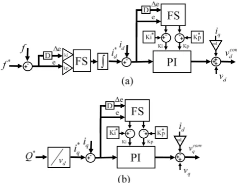
3- Modified fuzzy PI for grid-side controller
Grid-side controller block is depicted in Fig. 4. Fig. 4(a) shows d-axis double layer control block. The first layer is the fuzzy-like-PI controller for frequency regulation and generation of *
d
i . The second layer is a modified fuzzy PI
current controller. Fig. 4(b) shows q-axis single layer control block which is a modified fuzzy PI current controller. *
q
i is
calculated according to Q*as follows: *
* 2 3
q d
Q i
v
= (3)
3- 1- Fuzzy frequency regulator
In the fuzzy-like-PI controller of frequency regulator, FS operates like a PI controller. Inputs of the FS are error signal (
e) and its derivative (∆e) multiplied by kp and ki coefficients, respectively. Error is the difference of frequency reference value and calculated value by PLL. FS is based on Mamdani method [10]. Membership functions of input fuzzy sets are variable-width triangular as shown in Fig. 5 (Supposing per-unit scale, all of the input and output variables are in the range of [-1, 1] for fuzzification).
Fuzzy sets consist of seven fuzzy members for more precision: Negative Big (NB), Negative Medium (NM), Negative Small (NS), Zero (Z), Positive Small (PS), Positive Medium (PM) and Positive Big (PB). Table 1 shows the fuzzy rules of frequency regulator FS.
Fig. 4. Grid-side controller block
3- 2- Fuzzy PI current controllers
The modified fuzzy PI controller is used as a current controller for q-axis and d-axis in Fig. 4(b) and second layer of Fig. 4(a), respectively. The main difference of this structure with conventional PI current controller is the adaptive tuning of
p
K and Ki by means of FS. Inputs of the FS are error signal (
e
) and its derivative (∆e). This paper proposes a deviation-based approach for adaptive tuning of PI coefficients by the fuzzy system. It means that fuzzy system outputs are not PI coefficients directly. Rated PI coefficients ( *p
K and * i
K ) are optimally designed by feedback linearization and pole placement around the rated operating point. Since *
p
K and *
i
K are only optimal for the rated operating point, the fuzzy system output is added to them to change the PI coefficients when the operating point changes. This approach helps the fuzzy system to operate around the optimal setting of PI coefficients.
FS block consists of three layers, including fuzzification layer, inference mechanism (Mamdani method) with rule base and defuzzification layer. Fuzzy set of inputs and output has been shown in Fig 5 with triangle membership functions. Fuzzy sets consist of five fuzzy members: negative big
(NB), negative small (NS), zero (Z), positive small (PS) and positive big (PB).
The boundary of FS (A) is:
1
10X
for inputs A K for output
=
(4)
where x represents index i or p. Table 2 shows the fuzzy rules of FSs.
3- 3- Design of *
p
K and *
i
K
PI coefficients design needs the system model. The inverter can be modeled as a gain. Differential equations of the system in d and q axis are given by:
. , . . Ld Ld Ld Lq Lq Lq di
L V Ri
dt di
L V Ri
dt
= −
= − (5)
The Laplace transform of the above equatiom yields,
( ) 1 .
( ) Ld Ld
i s
V s =Ls R+ (6)
PI controller can be presented as: .
I
P K
K s
+ (7) So in a closed-loop system, the total transfer function has a second-order form as:
2
( ) .
(R K )s KP P I I
K s K T s
Ls
+ =
+ + + (8)
For this second-order system:
* * 2 2 , . p n i n
K L R
K L
ζω ω
= +
= (9)
ζ and
ω
n are damping factor and natural frequency of the second-order system. To choose an appropriate value for L and R also this point should be noted.Table 1. Fuzzy rules of frequency regulator.
NB ∆e
NM NS Z PS PM PB
e
NB PB PB PM PM PS Z Z
NM PB PM PM PS PS Z Z
NS PM PM PS PS Z NS NS
Z PM PS PS Z NS NS NM
PS PS PS Z NS NS NM NM
PM Z Z NS NS NM NB NB
PB Z Z NS NM NM NB NB
Fig. 6. Inputs and output fuzzy set of current controllers FS Table 2. Fuzzy rules of current controllers.
NB ∆e
NS Z PS PB
e
NB PB PB PS Z Z
NS PB PS Z Z Z
Z PS Z Z NS NS
PS Z Z NS NS NB
PB Z Z NS NB NB
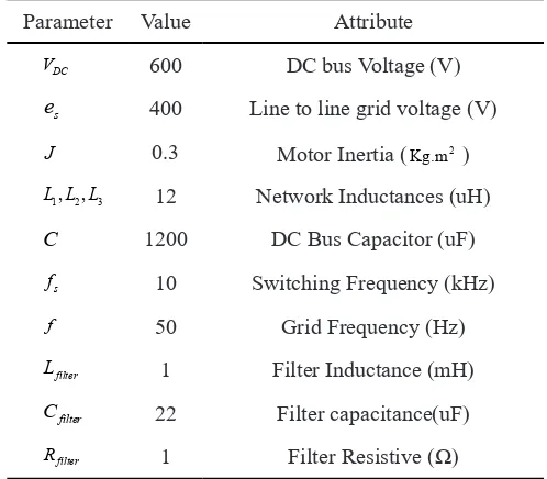
Table 3. Parameters of FESS & network
Attribute Value
Parameter
DC bus Voltage (V) 600
DC
V
Line to line grid voltage (V) 400
s
e
Motor Inertia (Kg.m2 )
0.3
J
Network Inductances (uH) 12
1, ,2 3 L L L
DC Bus Capacitor (uF) 1200
C
Switching Frequency (kHz) 10
s
f
Grid Frequency (Hz) 50
f
Filter Inductance (mH) 1 filter L Filter capacitance(uF) 22 filter C
Filter Resistive (Ω)
1 filter
4- Experimental results
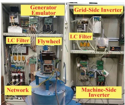
Experimental results of the proposed FESS control system in AUT microgrid is presented in this section. Experimental setup of AUT microgrid, including diesel generator emulator, grid-side inverter and machine-side inverter besides flywheel and network impedances can be seen in Fig. 7. The specifications of FESS and diesel generator emulator have been listed in Table 3 and Table 4, respectively. Fig. 6 shows the experimental set up of the microgrid.
The control systems of both FESS and generator emulator are implemented based on DSP chip TMS320F28335.
At first, the interaction of diesel generator emulator and resistive variable load, without FESS in islanding mode of microgrid operation are studied. In the next step, the existence of FESS for frequency regulation by conventional control system [8] is considered. Finally, FESS with the proposed control system is studied.
The islanded microgrid operation are studied in three cases as follows:
• without FESS,
• with FESS and conventional control system,
• with FESS and proposed control system.
The isolation switch of the microgrid is open, thus, the variable resistive load is only connected to diesel generator
emulator. Initial load is 300W. At t=10s, the load is suddenly increased to 1KW. The droop control system of diesel generator emulator operates and frequency drops as shown by black color in Fig. 8. Frequency values are collected from DSP chip using online GUI of CCS.6 software and plotted in MATLAB.
The same load change is accomplished with the presence of FESS, once with its conventional control system (scenario 2) and once with the proposed control system (scenario 3). Corresponding frequency variations are depicted in Fig. 8 by red and blue colors, respectively. Active power injection of diesel generator emulator and FESS, for each scenario can be seen in Figs. 9 and 10, respectively.
As can be seen in Fig. 10, providing the required active power
Fig. 10. FESS active power generation in scenario 1 (black), scenario 2 (red), and scenario 3 (blue).
Fig. 9. Diesel generator emulator active power generation in scenario 1 (black), scenario 2 (red), and scenario 3 (blue).
Fig. 8. Frequency variations in scenario 1 (black), scenario 2 (red), scenario 3 (blue).
Fig. 7. Experimental set up of AUT Microgrid
Table 4. Diesel generator emulator parameters.
Attribute Value
Parameter
DC bus Voltage (V) 600
DC
V
Line to line grid voltage (V) 400
s e
Filter Resistance (mΩ)
500 f
R
Filter Inductance (mH) 1
f L
Capacitor (uF) 22
f
C
DC Bus Capacitor (uF) 1200
C
Switching Frequency (kHz) 10
s f
Grid Frequency (Hz) 50
by FESS in scenario 1 and scenario 2, the frequency returns to 50 Hz. Faster response of the proposed FESS control system to the load change for active power compensation (scenario 3) in comparison to conventional FESS control system (scenario 2), leads to the less frequency drop (Fig. 8). The reason for more stable frequency regulation of the proposed control system is that fuzzy controller sensitivity to the operating point change is less than the conventional PI controller. Values of *
p
K and *
i
K which are used for conventional PI controllers in scenario 2 are 0.01 and 0.001, respectively (the system is per-unit). Kpand Ki for fuzzy current controllers in scenario 3, before the step load change, are 0.017 and 0.0013, respectively and after step load changes are 0.0095 and 0.00087, respectively.
DC link voltage of FESS for conventional and proposed FESS control systems is shown in Fig. 11. As can be seen, moving DC link voltage controller from grid-side to machine-side inverter control system does not result in a conmachine-siderable difference in DC link regulation quality. Although in the proposed method the settling time is more than the conventional method, it should be noted that according to Fig. 11, peak-to-peak value of the capacitor voltage oscillation is just 60v which is very smaller than 600v (DC link capacitor voltage) against a sudden step load change. On the other hand, this is a trade-off between the advantages of the proposed system and a little increase in settling time of DC link voltage. These advantages are:
• no need to transfer the measured frequency value of the network from grid-side inverter to machine-side inverter, • embedding both active and reactive power control loop
in the grid-side inverter control system (Implementation of fuzzy systems is limited to the grid-side inverter), • no need for extra codes in the microcontroller of the
machine-side inverter which is involved in FOC codes execution.
5- Conclusion
In this paper, a new fuzzy system-based control system was proposed for FESS in order to frequency regulation of an isolated microgrid. Experimental results show that moving DC link voltage controller from grid-side to machine-side
inverter control system does not result in a considerable difference in DC link regulation quality. Also, a faster response of the proposed FESS control system to the load change for active power compensation in comparison to conventional FESS control system leads to less frequency drop.
References
[1] M.A. Pedrasa, T. Spooner, A survey of techniques used to control microgrid generation and storage during island operation, in: Proceedings of the 2006 Australasian Universities Power Engineering Conference (AUPEC’06), (2006). 1-6.
[2] J.M. Guerrero, J.C. Vasquez, J. Matas, L.G. De Vicuña, M. Castilla, Hierarchical control of droop-controlled AC and DC microgrids—A general approach toward standardization, IEEE Transactions on industrial electronics, 58(1) (2010) 158-172.
[3] M.R. Aghamohammadi, H. Abdolahinia, A new approach for optimal sizing of battery energy storage system for primary frequency control of islanded microgrid, International Journal of Electrical Power & Energy Systems, 54 (2014) 325-333.
[4] R. Arghandeh, M. Pipattanasomporn, S. Rahman, Flywheel energy storage systems for ride-through applications in a facility microgrid, IEEE Transactions on smart grid, 3(4) (2012) 1955-1962.
[5] H.M. Hasanien, M. Matar, A fuzzy logic controller for autonomous operation of a voltage source converter-based distributed generation system, IEEE Transactions on Smart grid, 6(1) (2014) 158-165.
[6] T. Vigneysh, N. Kumarappan, Grid interconnection of renewable energy sources using multifunctional grid-interactive converters: A fuzzy logic based approach, Electric Power Systems Research, 151 (2017) 359-368.
[7] A.K. Arani, G. Gharehpetian, Enhancement of microgrid frequency control subsequent to islanding process using flywheel energy storage system, in: 2014 Smart Grid Conference (SGC), IEEE, (2014) 1-6.
[8] A.A. Khodadoost Arani, B. Zaker, G.B. Gharehpetian,
Induction machine‐based flywheel energy storage
system modeling and control for frequency regulation
after micro‐grid islanding, International Transactions on Electrical Energy Systems, 27(9) (2017) e2356.
[9] V. Vijay, P.G. Kini, C. Viswanatha, N. Adhikari, Regenerative load emulator with battery charging for evaluation of energy management in microgrid with
distributed renewable sources, in: 2015 Modern Electric Power Systems (MEPS), IEEE, (2015) 1-6.
[10] M.S. Mahdavi, B. Vahidi, G.B. Gharehpetian, A novel optimized fuzzy approach based on monte carlo method for system load, wind turbine and photovoltaic unit uncertainty modeling in unit commitment, Electric Power Components and Systems, 44(8) (2016) 833-842.
Pleasecitethisarticleusing:
M. S. Mahdavi, G. B. Gharehpetian, Parisa Ranjbaran, Hossein Azizi, Frequency Regulation of AUT Microgrid Using