International Journal of Industrial Electronics, Control and Optimization .
© 2020 IECO
….
Vol. 3, No. 2, pp. 159-172, April (2020)An Adaptive Control Method using Interval
Fuzzy Sliding Mode for Direct Matrix Converters
Mehdi Bekrani
1,†, Seyedeh Tahereh Behrooz
2, and Mojtaba Heydari
31,2,3 Faculty of Electrical and Computer Engineering, Qom University of Technology, Qom, Iran
In this paper, a new adaptive control method is proposed for direct matrix converters. The proposed method uses interval type-2 fuzzy logic integrated with sliding mode control. Employing the sliding mode control in matrix converters leads to an efficient choice of switching combinations and a reliable reference tracking. The main problem of the sliding mode control is the chattering phenomenon that degrades the controller performance through injecting high-frequency variations in the controller variables. The proposed method incorporates the interval type-2 fuzzy with the sliding mode control to mitigate the chattering problem. The sliding mode switch surface can be adjusted adaptively according to the system state and the proposed fuzzy compensation based on the Lyapunov stability theorem, so that the control system has the characteristics of low chattering effect and appropriate operation quality. Comprehensive evaluations of the waveforms are conducted for the new matrix converter through various simulations. Simulation results verify the effectiveness of the proposed adaptive control method for matrix converter in various conditions, and its superiority in chattering suppression in comparison to the conventional sliding mode control and the boundary layer method.
Article Info
Keywords:
Chattering suppression, Matrix converter, Sliding mode control, Type-2 fuzzy logic Article History:
Received 2019-07-07 Accepted 2019-12-15
I.
I
NTRODUCTIONIn recent years, AC-AC power converters have been extensively developed in various applications including AC motor drive systems, flexible AC transmission systems (FACTs), aircraft industry and wind energy conversion systems [1]-[4]. Such converters which are known as matrix converters (MCs) convert an AC waveform to another AC waveform with different voltage magnitude and frequency using minimum number of passive components [5]-[7].
Pulse width modulation (PWM) techniques are generally used for switching control of direct MCs. Alesina and Venturini [8]-[9] introduced a high frequency PWM method with low harmonic contents for both output voltages and input currents of MCs. Another switching technique introduced for direct MCs is space vector modulation (SVM) [10]. The
calculation steps in the SVM method are much simpler than those in the Venturini’s method due to a fewer number of calculations for sinusoidal functions. Moreover, the commutation of switches in the SVM method is 20% less in each cycle [11].
Space vector modulations of direct MC are classified into direct SVM[12] and indirect SVM [13], [14]. In the indirect SVM the direct MC is described as an equivalent circuit consisting of current source rectifier and voltage source inverter connected through a virtual DC link. In the direct SVM, however, the actual MC circuit is considered without any assumption of an equivalent circuit. The direct SVM strategy is more complicated than indirect SVM since modulation vectors vary continuously and depend on instantaneous magnitude of the source [15].
Several control schemes, often dealt with modulation strategies, have been presented for matrix converters, such as proportional-integral (PI) control techniques [12], [16], decoupled linear control techniques [17], predictive control techniques [18]-[20], and sliding mode control techniques [17], [21].
†Corresponding Author: [email protected]
Tel: +98-2536641601, Fax: +98-2536641604, Faculty of Electrical and Computer Engineering, Qom University of Technology, Qom, Iran
Controlling the matrix converters using the conventional PI control techniques is a challenging task, since multiple control objectives have to be simultaneously achieved [22]. The decoupled linear control techniques are only valid around an operating point and do not guarantee robustness [17]. The predictive control is of great versatility for its ability to treat with different requirements. The main disadvantage of the predictive control is, however, that a high content of harmonics may be generated at the output of the matrix converter [20].
The sliding mode control which was proposed during the late 1950s, benefits a high disturbance rejection capability, a low sensitivity to the variation of system parameters, and a high-speed response [23].Due to these advantages as well as easy implementation, the sliding mode controller can be efficiently employed in various industrial control applications [24]-[25]. The main drawback of this controller, however, is that its control signal exhibits high frequency oscillations, which is called the chattering problem [26]. This problem causes undesirable impacts on the control trajectory such as low accuracy and high heat losses in power circuits.
Among the various solutions to mitigate the chattering effect, the boundary layer approach is ofthe most popular one[21]. In the boundary layer approach, a thin boundary layer is considered neighbor the switching surface and makes the system trajectories stay within the predetermined boundary layer. As a result, the control discontinuity is smoothed out in a boundary layer around the switching surface. This solution, however, compromises on accuracy of the trajectory tracking. Another method in literature is high order sliding mode [27]-[29]. In the high order sliding mode, the sliding surface structures are improved at the cost of a higher complexity in the control structure. Combining with signal processing tools such as neural networks [30]-[31] and fuzzy logic controller [32]-[33], the chattering phenomenon can be reduced efficiently. The above hybrid methods use adaptive neural networks or fuzzy logics to approximate the unknown system model.
Recently, several hybrid fuzzy SMC methods have been developed. The methods proposed in [34] and [35] utilize fuzzy models to describe some uncertain nonlinear systems. In [36], an adaptive fuzzy approach is employed to approximate the unknown nonlinearity in the presence of signal quantization. In [37], a fuzzy regulator is proposed to adaptively smooth the hitting control and concurrently compensate for observation deviations. The work in [38] uses an adaptive neuro-fuzzy inference system (ANFIS) to estimate unknown part of the system dynamics based on the off-line input-output data. This ANFIS based control system provides more general solution for the singularity and chattering problems. As a result, the sliding gain is adapted to the estimated value of the unknown part and hence, provides a fast convergence and low chattering. However, this requires an
appropriate design procedure and a stability proof to guarantee the performance and the stability of the whole hybrid system [39]. In [40], the stability problem of the uncertain fuzzy systems is compensated via an adaptive SMC method. To this end, a fuzzy integral-type sliding surface is utilized and the SMC method is applied to estimate the unknown system parameters. In [41], an adaptive algorithm is utilized to estimate the system lumped disturbances, including parameter variations and external disturbances. This procedure avoids large switching gain which can lead to the occurrence of high-frequency sliding mode chattering. Besides, adaptive output feedback SMC is also designed for linear systems with matched external disturbances [42].
These hybrid methods provide partly some advantages over standard SMC such as reduced chattering, non-singularity, high precision, and finite-time convergence. However, these techniques need accurate tuning of controller parameters. In addition, the chattering phenomenon still occurs due to using the discrete control input and as a result, some additional methods are required to meet the chattering problem [38].
In this paper, a new adaptive control method of MC is proposed which is based on interval type-2 fuzzy sliding mode control using indirect SVM. In addition to the input current control development, the chattering phenomenon is reduced through integration of the interval type-2 fuzzy with sliding mode control strategy. In contrast to the previous chattering reduction methods in [21], [27], the proposed fuzzy integration method does not increase the error amplitude of the controller. As a result, the accuracy of the trajectory is enhanced and complex parameter tuning is avoided. In addition to an easy implementation, the interval type-2 fuzzy compensation does not require complicated membership function. Simulation results verify the efficient performance of the proposed adaptive control method for MCs.
This paper consists of five sections. The MC model and its inverter and rectifier stage modulations are described in Section 2. The proposed fuzzy sliding mode control for the direct MC is presented in Section 3. The performance assessment of the proposed control system is verified by simulation results in Section 4. Finally, the conclusion is brought in Section 5.
II.
T
HEMC
M
ODELInternational Journal of Industrial Electronics, Control and Optimization .
© 2020 IECO
….
Vol. 3, No. 2, pp. 159-172, April (2020)(1) Aa Ab Ac
Ba Bb Bc
Ca Cb Cc
S
S
S
S
S
S
S
S
S
S
where assuming 𝑗 ∈ {𝐴, 𝐵, 𝐶} and 𝑘 ∈ {𝑎, 𝑏, 𝑐}, we have
0
jk
S for corresponding switch to be open and Sjk1
for corresponding switch to be closed. The constraint
1, , ,
Ak Bk Ck
S S S k a b c is established to prevent
short-circuit of the input phases or open-circuit of the output phases [43]. Applying Kirchhoff's Current Law (KCL) on MC, the relation between the input and output currents is given by
(2)
,A BC ,
i o ab c
I
S I
where 𝐼𝑖,𝐴𝐵𝐶= [𝑖𝑖𝑎 𝑖𝑖𝑏 𝑖𝑖𝑐]𝑇 denotes the input current vector and 𝐼𝑜,𝑎𝑏𝑐= [𝑖𝑜𝑎 𝑖𝑜𝑏 𝑖𝑜𝑐]𝑇 denotes the output current vector. The superscript T denotes transpose of the vector.
In this study, the MC power loss is ignored. As a result, the input and output voltage vectors are related by
(3)
T
, ,
o abc i ABC
V
S V
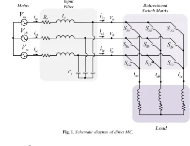
where 𝑉𝑜,𝑎𝑏𝑐= [𝑉𝑜𝑎 𝑉𝑜𝑏 𝑉𝑜𝑐]𝑇 denotes the output voltage vector and 𝑉𝑖,𝐴𝐵𝐶= [𝑉𝑖𝐴 𝑉𝑖𝐵 𝑉𝑖𝐶]𝑇 denotes the input current vector, as shown in Fig. 1.
III.
MC
M
ODEL WITHI
NPUTF
ILTERAssuming the input voltage source is a purely three-phase sinusoidal as
,
2
2
sin (
) sin (
) sin (
) ,
3
3
s abc om s s s
v
v
t
t
t
(4) where 𝜔𝑠 and
v
omare its frequency and peak voltage,respectively, applying Kirchhoff's Voltage Law (KVL) at the input side of MC, giving
(5)
,
,
,
sa sa f sa f iAsb sb f sb f iB
sc sc f sc f iC
di
V
R i
L
V
dt
di
V
R i
L
V
dt
di
V
R i
L
V
dt
in abc coordinates, where 𝑅𝑓 and 𝐿𝑓 are input resistance and inductance of the input filter, respectively. Furthermore, applying KCL on capacitors node at the input side of MC, we achieved
I
iaI
ibI
icMains
Input
Filter Bidirectional
Switch Matrix
Load
Fig. 1. Schematic diagram of direct MC.(6)
,
,
,
iAsa f ia
iB
sb f ib
iC
sc f ic
dV
i
C
i
dt
dV
i
C
i
dt
dV
i
C
i
dt
where 𝐶𝑓 is input capacitance of the input filter. For time invariant variables, designing the current controller is more convenient; hence, Equs. (5)-(6) are transformed to synchronous reference frame using Park transformation [44]. Thus, Equs. (5)-(6) in dq coordinates are transformed as
(7)
,
sd
sd f sd f f sq id
di
V
R i
L
L
i
V
dt
(8)
,
sqsq f sq f f sd iq
di
V
R i
L
L
i
V
dt
(9)
,
id
sd f f iq id
dV
i
C
C
V
i
dt
(10)
.
iq
sq f f id iq
dV
i
C
C
V
i
dt
where 𝑉𝑖𝑑 and 𝑉𝑖𝑞 are Park transform of 𝑉𝑖𝐴, 𝑉𝑖𝐵, and 𝑉𝑖𝐶. Similarly, 𝑉𝑠𝑑 and 𝑉𝑠𝑞 are Park transform of 𝑉𝑠𝑎, 𝑉𝑠𝑏, and
𝑉𝑠𝑐 . The current variables are also transformed to dq coordinates in a similar manner.
For simplicity, we assume that the impact of the input
inductance on the input filter is considered as disturbances
dand
q. As a result, Equs. (7)-(8) can be simplified to(11)
,
sd f sd id d
V
R i
V
(12)
.
sq f sq iq q
V
R i
V
Substituting Equ. (11) and Equ. (12) into Equ. (9) and Equ. (10), respectively, the input current state space model will be given by
1
,
sdsd f sq f f sq id d
f f
di
i
C
V
R C
i
i
dt
R C
(13)
1
.
sqsq f sd f f sd iq q f f
di
i
C
V
R C
i
i
dt
R C
(14) Equs. (13)-(14) provide the possibility of designing the sliding mode input current controller which will be described in the next section.
IV.
T
HEP
ROPOSEDM
ETHODIn this section, we utilize the findings of the previous section to design a sliding mode control procedure. We further incorporated it with an interval type-2 fuzzy approach to mitigate the chattering problem.
A. Adaptive Sliding Mode Controller Design Procedure
Regulation of the input active and reactive power is the main objective of the input current controller. The instantaneous active power (𝑃𝑖𝑛) and reactive power (𝑄𝑖𝑛) in the synchronous reference frame are given by
(15)
3 2
in sd sd sq sq
P V i V i
(16)
3 2
in sq sd sd sq
Q V i V i
In case the reference frame is oriented along the grid voltage, 𝑉𝑠𝑞 is equal to zero and consequently, Equs. (15)-(16) can be simplified to
(17)
3
,
2
in sd sdP
V i
(18)
3
.
2
in sd sqQ
V i
According to Equs. (17)-(18), active power and reactive power are proportional to the direct and quadrature current components, respectively. As a result, they can be controlled by controlling such current components. The sliding surfaces of input currents are as follows
(19)
*
q
i
sqi
sq
(20)
*
d
i
sdi
sd
where
i
sq* andi
*sd are the current reference components ofdq. In addition, the input current components of the rectifier stage are defined as
(21)
id idc id
i
i
i
(22) iq iqc iq
i
i
i
where
i
idcandi
iqcare continuous control terms and
i
idand
i
iqare corrective control terms. Assuming 𝑑𝜎𝑑,𝑞⁄𝑑𝑡=0 and 𝑑𝑖𝑑,𝑞∗ ⁄𝑑𝑡= 0, the continuous control terms can be achieved by
(23)
,
International Journal of Industrial Electronics, Control and Optimization .
© 2020 IECO
.
163NB NS Z PS PB
s
NB PB PS PS Z Z
NS PB PS PS Z Z
Z PS PS Z NS NS
PS Z Z NS NS NB
PB Z Z NS NS NB
.
iqc sq f sd f f sdi
i
C
V
R C
i
(24)The corrective terms of the sliding control inputs are given by
(25)
sign (
),
id d d
i
k
(26)
sign (
).
iq q q
i
k
Thus, Equs. (23)-(24) can be rewritten as
sign (
),
id sd f sq f f sq d d
i
i
C
V
R C
i
k
(27)sign (
).
iq sq f sd f f sd q q
i
i
C
V
R C
i
k
(28)By applying the Lyapunov criterion on input control signals,
d
k
andk
q can be achieved. Considering the switchingfunction vector as 𝐬 = [σd σq] T
, the Lyapunov function is defined as
(29)
𝑉 =12𝐬T𝐬 =1
2(𝜎𝑑2+ 𝜎𝑞2)
The Lyapunov criterion ensures the motion of the state trajectory to the switching surface and is expressed as
(30)
𝑉̇ = 𝐬T𝐬̇ = 𝜎̇
𝑑𝜎𝑑+ 𝜎̇𝑞𝜎𝑞< −𝜂(|𝜎𝑑| + |𝜎𝑞|)
where 𝑉̇ is the derivative of the Lyapunov function and η is a positive parameter. The inequality in Equ. (30) is satisfied if
(31)
𝜎̇𝑑𝜎𝑑< −𝜂|𝜎𝑑|
(32)
𝜎̇𝑞𝜎𝑞< −𝜂|𝜎𝑞|,
As a result, by applying Equ. (30), the constraints in Equs. (31)-(32) are given, respectively, by
(33 )
,m
(
)
1
(
)(
sign (
))
|
| (
),
sd
d d d
d d d d d d d
f f
di
dt
k
k
R C
(34 )
,m ( )
1
( )( sign ( )) | | ( ),
sq
q q q
q q q q q q q
f f di
dt
k k
R C
where
d,mand
q,mare the maximum amplitudes of thedisturbances. It should be noted that the value of 𝑅𝑓𝐶𝑓 is practically less than one and hence, the inequalities of Equs. (33)-(34) are true. Accordingly, we get
,m
|
d| (
d
k
d)
|
d|,
(35),m
|
q| (
q
k
q)
|
q|,
(36)Consequently, the constraints of 𝑘𝑑 and 𝑘𝑞 are given by
(37)
,m
d d
k
(38)
,m
q q
k
B. Fuzzy Chattering Compensation
To deal with the chattering phenomenon of SMC, the fuzzy rules are designed to improve the original control law. We apply interval type-2 fuzzy to reduce the chattering effect on the control process. To this end, the sliding surfaces 𝜎𝑑 and
𝜎𝑞 which are generally denoted here by 𝑠, and their derivatives which are denoted by 𝑠̇, are considered as the input variables of the fuzzy controller. In addition, the corresponding
fuzzy control output is denoted by
f . The interval fuzzyrules are determined in Table I. In this table, PB, PS, ZO, NB, and NS denote the linguistic variables Big, Positive-Small, Zero, Negative-Big, and Negative-Positive-Small, respectively. Compared to the procedure of [45], our proposed method has the same fuzzy rules, but we utilize type-2 fuzzy system which is considerably more robust to the model uncertainties with respect to the type-1 employed in [45]. In addition, we have extended our procedure to the matrix converter application.
The main source of chattering in the sliding mode control is un-modeled dynamics. As can be observed from Equs. (25)-(26), the corrective terms have the same value for different amount of s and ṡ depicted in Table I. In the interval type-2 fuzzy chattering compensation, values of corrective terms are taken into account. To this end, we propose improved corrective terms as follows
TABLEI
Rules of the membership function [45]
rules for ∆𝑓
(39)
sign (
)
id d d d
i
k
(40)
sign (
)
iq q q q
i
k
where Δ𝑑 and Δ𝑞are interval fuzzy compensation functions determined based on the Lyapunov stability constraint which is illustrated by Equs. (31)-(32).
Based on Lyapunov constraint, if 𝜎𝑑 is positive then 𝜎̇𝑑 should be negative and vice versa. The same fact is true for
𝜎𝑞and 𝜎̇𝑞. As a result, one could say that: if 𝜎𝑑 (similarly,
𝜎𝑞) is positive, then 𝜎̇𝑑 (𝜎̇𝑞) should be decreased while if 𝜎𝑑 (𝜎𝑞) is negative, then 𝜎̇𝑑 (𝜎̇𝑞) should be increased. To achieve the above conditions, we employ the fuzzy rules as shown in Table I for Δ𝑓 to reach the corresponding values for Δ𝑑 and
Δ𝑞 after defuzzification. As an example, if 𝜎𝑞 is NB and 𝜎̇𝑞 is NB, then the fuzzy controller should provide a PB value for
Δ𝑓, such that 𝜎̇𝑞 will become positive in a few step. Similarly, if 𝜎𝑞 is PB and 𝜎̇𝑞 is NB, then inequality in Equ. (32) is satisfied and we will set Δ𝑓 to zero (ZO).
The membership functions of the proposed interval type-2 fuzzy system for the input and output signals are triangular functions as illustrated in Figs. 2 and 3. The proposed lower membership function (LMF) and upper membership function (UMF) are chosen as shown in Figs. 2 and 3 with the aim of achieving a low chattering effect under the system uncertainties. The area between LMF and UMF functions
which denotes the footprint of uncertainty (FOU), are used to handle uncertainties existing in membership functions.
Type-reduction and defuzzifier stages are the last stages of the fuzzy compensator to achieve the crisp outputs Δ𝑑 and
Δ𝑞 from the fuzzy values of Δ𝑓 obtained from 𝜎𝑑 and 𝜎𝑞. Type-reduction is performed to change the type-2 output sets of the fuzzy logic system to a type-1 set. This set is then defuzzified to obtain a single crisp number. We employ the well-known "center of sets" method [46] for type-reduction and the "center of gravity" method is then utilized for defuzzification.
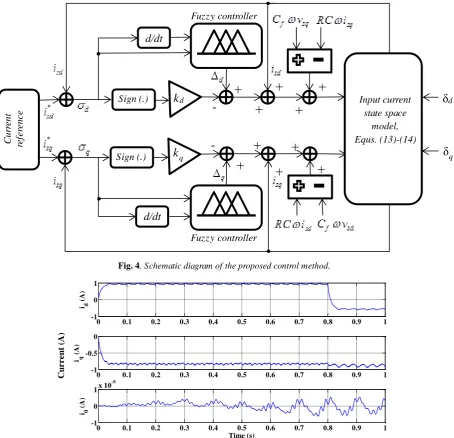
Fig. 4 illustrates the schematic diagram of the proposed control method. In summary, according to the input current state space model and the disturbances, sliding surfaces are determined. The fuzzy controllers utilize the sliding surfaces and their derivatives to provide the fuzzy compensator for the sliding mode control outputs to reduce the chattering effect.
V.
S
IMULATIONR
ESULTSSimulations are carried out using MATLAB. The simulation parameters are tabulated in Table II. As can be seen from Table II, 𝑇𝑠 (which is the sampling period) is 1e-4 sec. As a result, the sampling frequency is 10 kHz. This is equal to the maximum switching frequency that we use in our control method. According to the control law, we used a hysteresis switching and its value varies from 3.85 kHz to 10 kHz in our simulation.
According to the filter parameters in Table II and the filter design procedure provided in [47], the cut off frequency is equal to 2 kHz which is an appropriate value for a low pass filter designed for a matrix converter with the aforementioned interval of the switching frequency.
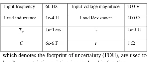
According to Equs. (17)-(18), the input active and reactive powers can be evaluated by 𝑖𝑠𝑑 and 𝑖𝑠𝑞, respectively. Therefore, the presentation of input current waveforms in the three-phase abc and synchronous reference frame will be informative.
Input frequency 60 Hz Input voltage magnitude 100 V
Load inductance 1e-4 H Load Resistance 100 Ω
𝑇𝑠 1e-4 sec L 1e-3 H
C 6e-6 F r 1 Ω
M
em
b
ersh
ip
d
eg
re
e
0 0.2 0.8 -0.2
-0.8
1 0.8
Z PS PB
NS NB
x
0 0.1 0.3
-0.1 -0.3
1 0.8
Z PS PB
NS NB
Fig. 2. Membership functions for s and 𝑠̇.
M
em
b
ersh
ip
d
eg
re
e
Δ𝑓
Fig. 3. Membership functions for Δ𝑓.
LMF UMF
LMF UMF
TABLEII
International Journal of Industrial Electronics, Control and Optimization .
© 2020 IECO
.
165The fundamental components of the input current in dq coordinates in the case of output frequency 𝑓𝑜= 10 Hz are shown in Fig. 5. The d component of the input current is suddenly changed from 1 A to -0.5 A at t=0.8 sec. As can be seen from Fig. 5, the proposed method is capable to vary the input current displacement factor from leading to lagging condition. The zero components of the three-phase currents are close to zero which illustrates that the input current is balanced. The magnitude of the output voltage is about 150 V. It is obvious that the open loop modulation of MC achieves a desirable response even at the moment of change in the input current displacement factor.
Fig. 6 (a) shows the output voltage for 𝑓𝑜= 10 Hz. The fast Fourier transform (FFT) analysis of the output voltage is also depicted in Fig. 6 (b). The Total Harmonic Distortion (THD)
index of the output voltage is equal to 26.37%, which can be reduced by designing a proper low-pass filter.
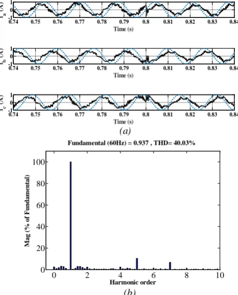
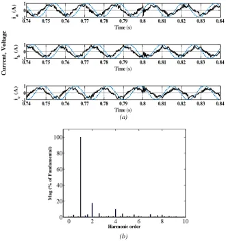
The normalized input current and grid voltage in abc
coordinates are shown in Fig. 7 (a) with the step change of the input displacement factor at t=0.8 sec. One can observe from Fig. 7 that the input current is properly changed from leading to lagging condition. Fig 7 (b) shows the FFT analysis of the input current. The achieved THD is 40.3%.
The performance of the proposed method is further evaluated for output frequencies higher than input frequency. Fig. 8 shows the fundamental components of the input current in dq coordinates for 𝑓𝑜= 100 Hz. The direct component of the input current is varied from 1 A to -0.5 A at t=0.8 sec. As can be observed, the proposed method varies the input current displacement factor from leading to lagging condition.
C
u
rr
en
t
ref
er
en
ce
Sign (.)
Sign (.)
d
k
q
k
Fuzzy controller
Fuzzy
d/dt
d/dt
Input current state space
model, Equs. (13)-(14)
d
δ
q
δ
-+
+
+
+
+
+
+
+
+
+
Fuzzy controller
Fig. 4. Schematic diagram of the proposed control method.
Fig. 5. Input current in dq coordinates when fo =10 Hz.
0 0.1 0.2 0.3 0.4 0.5 0.6 0.7 0.8 0.9 1
-1 0 1
id
(A
)
0 0.1 0.2 0.3 0.4 0.5 0.6 0.7 0.8 0.9 1
-1 -0.5 0
i q
(A
)
0 0.1 0.2 0.3 0.4 0.5 0.6 0.7 0.8 0.9 1
-1 0
1x 10
-9
i0
(A
)
Time (s)
Cu
rr
en
t
Fig. 9 (a) illustrates the output voltage for 𝑓𝑜= 100 Hz. As before, the magnitude of the output voltage is about 150 V. The FFT analysis of the output voltage is illustrated in Fig. 9 (b). The THD of the output voltage is 24.68% which is less than that for 𝑓𝑜= 10 Hz.
Fig. 10 (a) illustrates the normalized input current and the grid voltage in abc coordinates with the step change of the input current displacement factor at t=0.8 sec. It is obvious that the input current can be properly varied from leading to lagging condition when 𝑓𝑜 is higher than input frequencies. The FFT analysis of the input current is shown in Fig. 10 (b). The THD is 36.18% for this instant. It can be seen that in the same condition, the THD index in case of 𝑓𝑜= 100 Hz is less than that for 𝑓𝑜= 10 Hz.
In order to investigate the effect of the interval fuzzy on the chattering phenomenon, the simulation result of the switching surface 𝜎𝑑 is presented for different conditions. Fig. 11 (a) shows the FFT analysis for the case where type-2 fuzzy is not utilized and so Δ𝑑 and Δ𝑞 are considered to be zero. For the case where type-2 fuzzy is applied on the sliding mode is illustrated in Fig. 11 (b). As can be seen, the energy of the switching surface signal, which can be computed from the area under the curve, decreases by 40% through applying fuzzy compensation. As a result, the chattering phenomenon is mitigated significantly.
In order to provide more insight into the performance of the interval type-2 fuzzy in sliding mode control, Equs. (13)-(37)
are simulated through MATLAB/Simulink in which matrix converter is considered as current source due to space vector modulation of the input current. Moreover, the effect of the power switching is removed from output waveforms and hence, the impact of interval type-2 fuzzy on the sliding mode control method will be clear. The disturbances 𝛿𝑑 and 𝛿𝑞 are considered as normal random numbers of the range [-1, 1] with a high rate of variation which represents a severe disturbance for the controller.
Accuracy is one of the most essential criteria in the controller performance which is affected by the chattering phenomena. Fig. 12 illustrates the input current in synchronous reference frame before and after fuzzy compensation in sliding mode control. One can observe that type-2 fuzzy compensation aids the controller for rejecting the disturbance of the model. Moreover, the input currents error has decreased significantly along with chattering phenomenon through utilizing type-2 fuzzy compensation.
A comparison between type-2 fuzzy compensation method and boundary layer method is further presented. The performance measures for comparison are accuracy and chattering suppression. The chattering phenomenon is Fig. 6. Output three-phase voltage of MC for 𝑓𝑜= 10 Hz,
(a) three-phase waveform of output voltage, (b) FFT analysis of phase a of output voltage.
0 2 4 6 8 10
0 20 40 60 80 100
Harmonic order
Fundamental (10Hz) = 127.5 , THD= 26.37%
M
ag
(%
o
f
F
u
n
d
am
en
ta
l)
(a)
(b)
Fig. 7. Normalized input current and voltage for 𝑓𝑜= 10 Hz. (a) three-phase waveform of input current and input voltage, (b)
FFT analysis of phase A of input current (dotted-line: voltage waveform, solid-line: current waveform).
(a)
(b)
0.74 0.75 0.76 0.77 0.78 0.79 0.8 0.81 0.82 0.83 0.84 -1
0 1
Time (s)
ia
(
A
)
0.74 0.75 0.76 0.77 0.78 0.79 0.8 0.81 0.82 0.83 0.84 -1
0 1
Time (s)
ib
(
A
)
0.74 0.75 0.76 0.77 0.78 0.79 0.8 0.81 0.82 0.83 0.84 -1
0 1
Time (s)
ic
(
A
)
0 2 4 6 8 10
0 20 40 60 80 100
Harmonic order
Fundamental (60Hz) = 0.937 , THD= 40.03%
M
a
g
(%
o
f
F
u
n
d
a
m
en
ta
International Journal of Industrial Electronics, Control and Optimization .
© 2020 IECO
.
167investigated through calculating the area under FFT curve with
respect to the frequency of switching surfaces which here is called signal energy for both methods. We note that, the calculation of the area under FFT curve can be achieved using summation across all frequency components of FFT curve which, as a consequence of Parseval's relation, is equal to the signal energy [48]. The disturbance condition of the controller is considered the same as that for the previous simulation. As can be seen from Fig. 13, compared to the boundary layer
method, the proposed method achieves a lower energy of switching surface signal and hence, a lower chattering effect. This means a better performance is achieved using the proposed method.
Fig. 13 compares the accuracy of the type-2 fuzzy compensation method and the boundary layer method. One can observe that the type-2 fuzzy compensation method is more robust in eliminating process disturbances. Moreover, the type-2 fuzzy compensation method is more capable of tracking the reference value which illustrates a better accuracy of the proposed method.
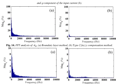
Figs. 14 and 15 show the FFT analysis of 𝜎𝑑 as well as 𝜎𝑞 for both type-2 fuzzy and the boundary layer methods. The energies of the switching signals are also shown in that figures. It can be seen that the energy of switching signal for type-2 fuzzy compensation method has been decreased approximately 40% in comparison to that for the boundary layer method. It can be concluded that the proposed control method could significantly mitigate the chattering phenomenon and increase the controller accuracy and robustness.
VI.
C
ONCLUSIONSIn this paper, a new input current control method was proposed for matrix converter which utilizes the interval type-2 fuzzy logic integrated with the sliding mode. The proposed control method utilized a fuzzy compensation approach to adaptively adjust the sliding surfaces. It was illustrated in simulation results that the energy of the switching signal was decreased about 40%. In addition, the chattering phenomenon was significantly decreased, while the control accuracy was maintained against large disturbances. This is in contrary to the conventional chattering suppression approaches such as boundary layer method, where chattering reduction is achieved at the price of sacrificing the control accuracy. The simulation Fig. 9. Output three-phase voltage of MC when 𝑓𝑜= 100 Hz,
(a) three-phase waveform of output voltage, (b) FFT analysis of phase a of output voltage.
0 2 4 6 8 10
0 20 40 60 80 100
Harmonic order
Fundamental (100Hz) = 127 , THD= 24.68%
M
a
g
(%
o
f
F
u
n
d
a
m
e
n
ta
l)
(a)
(b)
0 0.01 0.02 0.03 0.04 0.05 0.06 0.07 0.08 0.09 0.1
-200 -150 -100 -50 0 50 100 150 200
Time (s)
v
out(V
)
0 0.01 0.02 0.03 0.04 0.05 0.06 0.07 0.08 0.09 0.1
-200 -150 -100 -50 0 50 100 150 200
Time (s) vou
t
(V
)
0 0.01 0.02 0.03 0.04
Time (s)
V
o
ltag
e,
vo
u
t
(
V
)
0 0.1 0.2 0.3 0.4 0.5 0.6 0.7 0.8 0.9 1
-1 0 1
id
(A
)
0 0.1 0.2 0.3 0.4 0.5 0.6 0.7 0.8 0.9 1
-1 -0.5 0
iq
(A
)
0 0.1 0.2 0.3 0.4 0.5 0.6 0.7 0.8 0.9 1
-5 0 5x 10
-10
i0
(A
)
Time (s)
Fig. 8. Input current in dq coordinates for 𝑓𝑜= 100 Hz.
Cu
rr
en
t
results further verified the effective performance of the proposed method in changing the input current displacement factor from leading to lagging.
Fig. 10. Normalized input current and voltage for 𝑓𝑜= 100 Hz, (a) three-phase waveform of input current and input voltage
(solid-line: voltage waveform, dotted-line: current waveform), (b) FFT analysis of phase A of input current.
0.74 0.75 0.76 0.77 0.78 0.79 0.8 0.81 0.82 0.83 0.84
-1 0 1
Time (s)
i a
(
A
)
0.74 0.75 0.76 0.77 0.78 0.79 0.8 0.81 0.82 0.83 0.84
-1 0 1
Time (s)
i b
(
A
)
0.74 0.75 0.76 0.77 0.78 0.79 0.8 0.81 0.82 0.83 0.84
-1 0 1
Time (s)
i c
(
A
)
C
u
rr
en
t,
Vo
lta
g
e
(a)
(b)
Fig. 11. FFT analysis of the switching surface, (a) without interval fuzzy compensation, (b) with interval fuzzy compensation.
0 2000 4000 6000 8000 10000
0 0.05 0.1 0.15 0.2
Frequency (Hz)
M
a
g
d
0 2000 4000 6000 8000 10000 0
0.05 0.1 0.15 0.2
Frequency (Hz)
d
M
a
g
(a) (b)
0 2 4 6 8 10
0 20 40 60 80 100
Harmonic order
Fundamental (100Hz) = 127 , THD= 24.68%
M
a
g
(%
o
f
F
u
n
d
a
m
e
n
ta
International Journal of Industrial Electronics, Control and Optimization .
© 2020 IECO
.
169Fig. 13. Accuracy comparison between type-2 fuzzy and boundary layer method for d component of input current (a) and q component of the input current (b).
0.6 0.7 0.8 0.9 1 1.1 1.2 1.3 1.4
-0.8 -0.7 -0.6 -0.5 -0.4
Time (s)
isd
, i
* (sd
A
)
i
sd
i*sd
Boundary layer method (a)
Fuzzy type-2 compensation method
0.6 0.7 0.8 0.9 1 1.1 1.2 1.3 1.4
-0.75 -0.7 -0.65 -0.6
Time (s)
isq
, i
* (sq
A
) isq
i*
sq
Fuzzy type-2
compensation method Boundary layer method (b)
Fig. 14. FFT analysis of 𝜎𝑑, (a) Boundary layer method, (b) Type-2 fuzzy compensation method.
0.5 1 1.5
-0.7 -0.65 -0.6 -0.55 -0.5 -0.45 -0.4 -0.35
Time (s)
i sd
, i
* ( sd
A
) i*
sd i
sd
After applying fuzzy type-2 compensation
(a)
SMC method
0.5 1 1.5
-0.8 -0.75 -0.7 -0.65 -0.6
Time (s)
isq
, i
* (sq
A
)
i sq
i* sq
After applying fuzzy type-2 compensation
(b)
SMC method
Fig. 12. Accuracy analysis of the fuzzy compensation for d component of input current (a), and q component of input current (b).
R
EFERENCES[1] X. Li, M. Su, Y. Sun, H. Dan, and W. Xiong,“Modulation strategy based on mathematical construction for matrix converter extending the input reactive power range,” IEEE Trans. Power Elec., Vol. 29, No. 2, pp. 654-664, Feb. 2014. [2] P. Cardenas, R. Pena, G. Tobar, J. Clare, P. Wheeler, and G. Asher, “Stability analysis of a wind energy conversion system based on a doubly fed induction generator fed by a matrix converter,” IEEE Trans. Ind. Electron, Vol. 56, No. 10, pp. 4194–4206, Oct. 2009.
[3] J. Monteiro, J. F. Silva, S. F. Pinto, and J. Palma, “Matrix converter based unified power-flow controllers: Advanced direct power control method,” IEEE Trans. Power Del., Vol. 26, No. 1, pp. 420–430, Jan. 2011.
[4] R. Vargas, U. Ammann, B. Hudoffsky, J. Rodriguez, and P.Wheeler, “Predictive torque control of an induction machine fed by a matrix converter with reactive input power control,” IEEE Trans. Power Electron., Vol. 25, No. 6, pp. 1426–1438, June 2010.
[5] Ch. Xia, Y. Yan, P. Song, and T. Shi, “Voltage disturbance rejection for matrix converter-based PMSM drive system using internal model control,” IEEE Trans. Ind. Electron. Vol. 59, No. 1, pp. 361 – 372, Jan. 2012.
[6] P. W. Wheeler, J. Rodrïguez, J. C. Clare, L. Empringham, and A.Weinstein, “Matrix converters: A technology review,”
IEEE Trans. Ind. Electron., Vol. 49, No. 2, pp. 276–288, Apr. 2002.
[7] O. Simon, J. Mahlein, M. N. Muenzer, and M. Bruckmann, “Modern solutions for industrial matrix-converter applications,” IEEE Trans. Ind. Electron., Vol. 49, No. 2, pp. 401–406, Apr. 2002.
[8] A. Alesina and M. Venturini, “Solid-state power conversion: a Fourier analysis approach to generalized transformer synthesis,” IEEE Trans. Circuits Syst., Vol. 28, No. 4, pp. 319–330, Apr. 1981.
[9] A. Alesina and M. Venturini, “Analysis and design of optimum amplitude nine-switch direct AC–AC converters,”
IEEE Trans. Power Electron., Vol. 4, No. 1, pp. 101–112, Jan. 1989.
[10] T. D. Nguyen and H. H. Lee, "Development of a three-to-five-phase indirect matrix converter with carrier-based PWM based on space-vector modulation analysis," IEEE Trans. Ind. Electron., Vol. 63, No. 1, pp. 13-24, Jan. 2016. [11] L. Zhang, C. Watthanasarn, and W. Shepherd, "Control of
AC-AC matrix converters for unbalanced and/or distorted supply voltage," IEEE Power Electronics Specialists Conference, Vol. 2, pp. 1108-1113, Feb. 2001.
[12] D. Casadei, G. Serra, A. Tani, and L. Zarri, “Matrix converter modulation strategies: A new general approach based on space-vector representation of the switch state,”
IEEE Trans. Ind. Electron., Vol. 49, No. 2, pp. 370– 381, Apr. 2002.
[13] L. Huber and D. Borojevic, “Space vector modulated three phase to three-phase matrix converter with input power factor correction,” IEEE Trans. Industry Applications, Vol. 31, No. 6, pp. 1234–1246, Nov./Dec. 1995.
[14] Z. Xu, “An indirect space-vector modulated three-phase AC-DC matrix converter for hybrid electric vehicles,”
Energy Procedia, Vol. 75, pp. 1968-1974, Aug. 2015. [15] A. Shabanpour, S. Gholami, and A. R. Seifi. “Comparative
studies of different switching patterns for direct and indirect space vector modulated matrix converter,” Advances in power Electronics, Hindawi Publishing Corporation, Vol.
2012, pp. 1-8, 2012.
[16] A. Schuster, “A matrix converter without reactive clamp elements for an induction motor drive system,” IEEE Power Electronics Specialists Conference, Vol. 1, pp. 714–720, May 1998.
[17] J. Monteiro, J. F. Silva, S. F. Pinto, and J. Palma, “Linear and sliding-mode control design for matrix converter-based unified power flow controllers,” IEEE Trans. Power Electron., Vol. 29, No. 7, pp. 3357-3367, July 2014. [18] M. Vijayagopal, P. Zanchetta, L. Empringham, L. de Lillo,
L. Tarisciotti, and P. Wheeler, "Control of a Direct Matrix Converter with Modulated Model Predictive Control,"
IEEE Trans. Industry Applications, Vol. 53 , No. 3 , pp. 2342 – 2349, May 2017.
[19] S. Vazquez, J. Rodriguez, M. Rivera, L. G. Franquelo, and M. Norambuena, "Model Predictive Control for Power Converters and Drives: Advances and Trends," IEEE Trans. Industrial Electronics, Vol. 64, No. 2, pp. 935 – 947, Feb. 2017.
[20] F. Gavil´an, S. Toledo, M. Rivera, D. Caballero, E. Maqueda, and R. Gregor, "Predictive Current Control Strategy for a Direct Matrix Converter with Modulated Switching Pattern," IEEE International Conference on Automation/XXIII Congress of the Chilean Association of Automatic Control, 2018.
[21] S. Pinto, and J. Silva, "Sliding mode direct control of matrix converters," IET Electric Power Applications, Vol. 1, No. 3, pp. 439-448, June 2007.
[22] J. Rodriguez, P. Cortes, R. Kennel, M. P. Kazrnierkowski, “Model Predictive Control - A Simple and Powerful Method to Control Power Converters,” IEEE International Power Electronics and Motion Control Conference, pp. 41-49, May 2009.
[23] R. Sedaghati, and M. R. Shakarami, "A new sliding mode-based power sharing control method for multiple energy sources in the microgrid under different conditions,"
International Journal of Industrial Electronics, Control and Optimization, Vol. 2, No. 1, pp. 25-38, Jan. 2019.
[24] Y. Sun, X. Li, M. Su, H. Wang, H. Dan, and W. Xiong. “Indirect matrix converter-based topology and modulation schemes for enhancing input reactive power capability,”
IEEE Trans. Power. Electron., Vol. 30, No. 9, pp. 4669-4681, Sep. 2015.
[25] W. Gao, and J. Hung, “Variable structure control of nonlinearsystems: a new approach,” IEEE Trans. Indust. Electron., Vol. 40, No. 1, pp. 45–54, Feb. 1993.
[26] S. Haghighatnia, H. Toosian Shandiz, and A. Alfi, "Conformable fractional order sliding mode control for a class of fractional order chaotic systems," International Journal of Industrial Electronics, Control and Optimization, Vol. 2, No. 3, pp. 177-188, July 2019.
[27] L. Hoon and V. I. Utkin, "Chattering suppression methods in sliding mode control systems," Annual reviews in control, Vol. 31, No. 2, pp. 179-188, Dec. 2007.
[28] M. Van, H. J. Kang, and Y. S. Suh, "Second order sliding mode based output feedback tracking control for uncertain robot manipulators," International Journal of Advanced Robotic Systems, Vol. 10, No. 1, pp. 1-9, 2013.
[29] M. Van, H. J. Kang, and K. S. Shin, "Backstepping quasi-continuous high-order sliding mode control for a T-S fuzzy system with an application for a two-link robot control,"
International Journal of Industrial Electronics, Control and Optimization .
© 2020 IECO
.
171[30] C. E. Castaneda, A. G. Loukianov, E. N. Sanchez, and B. Castillo-Toledo, "Discrete-time neural sliding-mode block control for a DC motor with controlled flux," IEEE Trans. Industrial Electronics, Vol. 59, No. 2, pp. 1194-1207, Feb. 2012.
[31] S. Wen, M. Z. Q. Chen, Z. Zeng, T. Huang, and C. Li, "Adaptive neural-fuzzy sliding-mode fault-tolerant control for uncertain nonlinear systems," IEEE Trans. Systems, Man, and Cybernetics: Systems, Vol. 47, No. 8, pp. 2268-2278, Aug. 2017.
[32] J. Zhang, Y. Lin, and G. Feng, "Analysis and synthesis of memory-based fuzzy sliding mode controllers," IEEE Trans. Cybernetics, Vol. 45, No. 12, pp. 2880-2889, Dec. 2015. [33] T. H. Ho and K. K. Ahn, "Speed control of a hydraulic
pressure coupling drive using an adaptive fuzzy sliding-mode control," IEEE/ASME Trans. Mechatronics, Vol. 17, No. 5, pp. 976-986, Oct. 2012.
[34] Q. Gao, G. Feng, Z. Xi, Y. Wang, and J. Qiu, “Robust control of T–S fuzzy time-delay systems via a new sliding-mode control scheme,” IEEE Trans. Fuzzy Systems, Vol. 22, No. 2, pp. 459–465, 2014.
[35] H. Li, J. Wang, L. Wu, H. K. Lam, Y. Gao, "Optimal guaranteed cost sliding mode control of interval type-2 fuzzy time-delay systems," IEEE Trans. Fuzzy Systems, Vol. 26, No. 1, pp. 246-257, Feb. 2018.
[36] L. Chen, M. Liu, X. Huang, Sh. Fu, and J. Qiu, "Adaptive fuzzy sliding mode control for network-based nonlinear systems with actuator failures," IEEE Trans. Fuzzy Systems, Vol. 26, No. 3, pp. 1311 – 1323, June 2018.
[37] S. Y. Chen, H. H. Chiang, T. Sh. Liu, Ch. H. Chang, "Precision motion control of permanent magnet linear synchronous motors using adaptive fuzzy fractional-order sliding-mode control," IEEE/ASME Trans. Mechatronics, Vol. 24, No. 2, pp. 741 – 752, Apr. 2019. [38] Kh. Akbari, B. Rezaie, and S. Khari, "Designing full-order
sliding mode controller based on ANFIS approximator for uncertain nonlinear chaotic systems," International Journal of Industrial Electronics, Control and Optimization, Vol. 2, No. 1, pp. 39-46, Jan. 2019.
[39] M. Van, "An enhanced robust fault tolerant control based on an adaptive fuzzy PID-nonsingular fast terminal sliding mode control for uncertain nonlinear systems," IEEE/ASME Trans. Mechatronics, Vol. 23, No. 3, pp. 1362 – 1371, June 2018.
[40] H. Li, J. Wang, H. Du, and H. R. Karimi, "Adaptive sliding mode control for Takagi–Sugeno fuzzy systems and its applications," IEEE Trans. Fuzzy Systems, Vol. 26 , No. 2 , pp. 531-542, Apr. 2018.
[41] J. Liu, H. Li, and Y. Deng, "Torque ripple minimization of PMSM based on robust ILC via adaptive sliding mode control," IEEE Trans. Power Electronics, Vol. 33, No. 4, pp. 3655 – 3671, Apr. 2018.
[42] J. Zhang and W. X. Zheng, “Design of adaptive sliding mode controllers for linear systems via output feedback,”
IEEE Trans. Ind. Electron., Vol. 61, No. 7, pp. 3553–3562, July 2014.
[43] J. J. Slotine and S.S. Sastry, “Tracking control of nonlinear systems using sliding surfaces with application to robot manipulator,” International Journal of Control, Vol. 38, No. 2, pp. 465–492, June 1983.
[44] D. Mondal, A. Chakrabarti, and A. Sengupta, Power system small signal stability analysis and control, Academic Press, 2014.
[45] Ch. Y. Liang and Sh. W. Tan, "A new approach to
chattering reduction in the sliding mode controls," Int. Conf. on Innovative Computing, Information and Control, pp. 334-337, Sep. 2007.
[46] J. M. Mendel, Uncertain rule-based fuzzy logic systems: introduction and new directions, Upper Saddle River, NJ: Prentice-Hall, 2001.
[47] V. Vlatkovic, D. Borojevic, and F.C. Lee, “Input filter design for power factor correction circuits,” IEEE Trans. Power Electron., Vol. 11, No. 1, pp. 199–205, Jan. 1996. [48] A. V. Oppenheim, A. S. Willsky, and H. Nawab, Signals
and Systems, 2nd Ed., Prentice Hall, 1997.
Mehdi Bekrani received the B.Sc. degree from Ferdowsi University of Mashhad, Mashad, Iran, in 2002, and the M.Sc. and Ph.D. degrees from Tarbiat Modares University, Tehran, Iran, in 2004 and 2010, respectively, all in electrical engineering. From 2010 to 2012, he was a Research Fellow at Nanyang Technological University, Singapore. In 2013, he joined Qom University of Technology, Qom, Iran, as an Assistant Professor in the Faculty of Electrical and Computer Engineering. His current research interests include adaptive algorithms, ultrasonic phased array systems, and acoustic signal processing.
Seyedeh Tahereh Behrooz was born in Shiraz, Iran. She received her B.Sc. degree in Electronics Engineering from Shiraz University, Iran, in 2014, and her M.Sc. in Power Electronics from Qom University of Technology, Qom, Iran, in 2016. She is currently a Ph.D. student in Islamic Azad University, Shiraz Branch, Iran. Her current research interests include AC-AC converters, AC-DC microgrids, and Fuzzy controllers.
IECO