Formal Process Algebraic Modeling and
Verification of Service Composition Based on
BPMN
Zahra Baatmaanghelich1, Ali Rezaee2, Sahar Adabi3
Received (2017-03-01) Accepted (2017-10-30)
Abstract — One of areas with the greatest needs having available information at the right moment and with high accuracy is healthcare. The right information at right time saves lives. Healthcare is a vital domain which needs high processing power for high amounts of data. Due to the critical and the special characteristics of these systems, formal
methods are used for specification, description, and verification. The goal of this research is to turn a
business process graphical diagram into a formally based model. In this work, BPMN has been extended to add time and probability information and then has been transferred to probabilistic real-time CSP area. This mapping can be employed
as a basic model for modeling different system
characteristics. This mapping, then, is modeled using a case study in pervasive healthcare domain
and verified in a model checking tool.
Index Terms — Formal methods, CSP, BPMN, Pervasive healthcare, Model checking.
I. INTRODUCTION
S
ervice oriented computation (SOC) appeared in 1990 decade. SOC organizes programs and software infrastructures in the form of a set of interacting services relying on service oriented architecture (SOA). SOA is an architecture which provides publishing, discovering and using services via other programs or services. Its aim is to achieve platform independent service oriented computation based on standards and loosely coupled components [1].The actual capacity of service-oriented architecture can only be achieved by composing services into powerful programs. In addition to service, what is needed for service composition is full and accurate details of service behavior while working with more complex and larger collection of services which describes service role as a part of the package. Web services are the best technology for implementing SOA and its strategic goals. Web service is a well-defined abstraction of a set of computing activities which includes some resources to meet a customer or a business process requirement [1].
There are two ways to describe the arrangement of business process activities: Orchestration and Choreography. Orchestration represents an executable business process which is described and controlled from a central unique point and orchestrates interaction of different services. While in the choreography, each participant describes its contribution to the composition. Choreography represents a description of the observable behavior of each participant in the composition includes exchanging public messages, transactions rules and an agreement 1,3 - Department of Computer Engineering, Science and
tools like BPMN and activity diagram.
We have chosen health care domain to be our business process diagram (BPD) case study. The main challenge in healthcare domain is how to provide better services to people while the financial and human resources are limited and human population is increasing [2]. Pervasive healthcare is the solution of many current problems and has a bright future for healthcare services. Pervasive healthcare is defined as healthcare services for everywhere every time while increases service quality. The more expanded definition includes prevention, health checkups, and maintenance, monitoring short-term (home health monitoring), long-term monitoring (nursing home), personal health monitoring, diagnosis and management of disease outbreaks, emergency, patient transfer and treatment [3]. Because there are many challenges in today’s health care arena and also the clear vision of the future, we’ve chosen our business process case study from this domain. In this research, we’ve extended BPMN diagram to add time and have derived a mapping from BPD to Probabilistic Real-time CSP, to be a basic formal model for software development. A brief and a comprehensive description of BPMN can be found in [4] and [5,6] respectively.
II. RELATED WORKS
Lanz [7] introduced time patterns for comparing and evaluating PIAS (Process-Aware Information Systems) systems and defined these patterns formally. Kallel [8] had a review on modeling and verifying time properties solutions in business processes, and extracted main challenges of this field. El-Hichami [9] presented a user-friendly graphical interface to enable business process experts to the early validity of dynamic behaviors and design constraints. Also, formal semantics and verification solution is presented. Guisheng Fan [10] presented a describing formal language to model different components of service composition and has used it to analyze system reliability, he verified his method by PetriNet. Rezaee [11] introduced a Fuzzy Inference Cloud Service (FICS) and modeled it using CSP formal language, Also, he did four tests on his model: consistency,
rules of a natural language, then converted that general rules to a logical formal notation which is domain and tool independent. In [13], the author described workflow patterns of service composition, analyzed their characteristic and performance PetriNet to the (max,+) algebra. And provided rules for mapping workflows in PetriNet to the (max,+) algebra. Dumez [14] presented a solution for specification, verification, and implementation of model-driven composite services. He used formal methods specially formal description language, LOTOS, to verify composite service in the specification phase.
III. FORMAL MODELING
CSP is a formal language which presents a well-formed formal algebra which is used in the industry to model and verify distributed and concurrent systems. A CSP process is like a black box includes several events. Process alphabet is a collection of events which the process can use. The process uses events and also channels to interact other processes [11]. The following is the brief description of expression (1):
STOP is the deadlock process which is not able to progress. SKIP is an event to determine a successful termination [hoar]. The process “b→P” continues to wait until the environment performs “b”. Once the event has occurred, the behavior of “b→P” will be the behavior of the process “P” [11]. “P□Q” determines deterministic choice so that the environment decides to select “P” or “Q”, sending a special initial event to one of the processes. While in nondeterministic choice, “P□Q”, the environment suggests a collection of events to the process and the process decides to accept or refuse events. In a non-deterministic process, some internal decisions can lead to unreliable behavior in future.
Processes communicate each other via channels to path messages. “chin?x → P” means an item is red from channel “chin”, placed to x and then process behavior is the same as “P”. “chout!x → P” means an item is placed on channel “chout”, and then process behavior is the same as “P” [11].
the combined process first behaves as “P”, if “P” terminates successfully then behaves as “Q”. The parallel lock-step synchronization of process “P” and process “Q” is shown by “P||Q”, in which “P” and “Q” processes must synchronize on the events which are both in the alphabet set of “P” and “Q” processes. The interleaving composition indicated by “P|||Q” does not perform synchronization based on common alphabets, and instead “P” and “Q” processes can communicate by using common channels [11].
“P
⊀
x Q” indicates a conditional processwhich “x” is the condition and if evaluated to true the process behaves as “P” otherwise behaves as “Q”. More descriptions on CSP can be found in [15] and [16].
IV. SUGGESTED MAPPING ALGORITHM
The aim is to specify a method that an analyzer can analyze time constraints and time criterions in the design phase. Analyzer takes BPD of a system, models it to CSP according to the mapping method we’ll explain here. If some reformation needed, modified design will come back to the analyzer to model it again. So, the system will refine during a recursive process to reach the desired quality.
1. Processes and Communications
For each pool consider a process: PoolName();. For each lane in a pool, consider a process with three sub-processes as: a main process “body”, a receive process “r” and a send process “s”. Process “body” follows the activities and events seen in the lane, and receive process and send process are responsible for exchanging messages between outside of the body. Further, we will explain “r” and “s” processes in detail.
Each activity in BPD can be mapped a simple process as:
ActivityName() = activityname -> Skip; To map the communications, we declare a category for created processes in CSP: main processes and subsidiary processes. And also a category for CSP channels: external channels and internal channels. Main processes include Pool,
Lane and any process in this level such as control process. Subsidiary processes include sub-processes in the main sub-processes and also activity processes. The structure of communication is the major difference between these two categories of processes. A subsidiary process doesn’t have external channels or sometimes it doesn’t have any channels like activity processes. A main process has send/receive sub-processes and communicates via external channels with other main processes. In fact, s/r sub-processes are the interfaces of a main process to the outside world. While subsidiary processes don’t have interface.
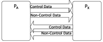
In BPD, a control flow element crossed over a lane border determines an external communication (message passing). Generally, for every two main processes which communicate each other, we consider 4 channels conforming figure (1). Having more than one reader or writer for a channel can cause data items lost or conflict. So, we separated the receiving channel and the sending channel for each process to avoid data confliction. We, also, separated channels for data items and control items to avoid data traffics when we need to send a control item immediately.
For message passing, we use a pattern as follow. All messages sent or received from/to body, are compound messages with three parts: P.T.M. “P” represents destination process name for out coming messages or source process name for incoming messages. “T” represents the type of message which can be D (data) or C (control). “M” is the message itself and it is the only thing that we see on the external channels. The two previous parts will be extracted in the “Send” interface layers or will be attached in the “Receive” interface layers. The reason of using this message structure is explained in the next section.
the send interface. Sending interface has been mapped to PA_s() process which has two layers:
- The first layer contains Prepare_Send_ PA() process which takes messages from body, extracts first part of messages and according to that, distributes them between SendTo processes.
- In the Second layer, for each destination process which receives a message from PA, there is a SendTo process. SendTo process extracts second part of a message, check if it is data or control, and puts only the last part on the correct external channel.
“Send” interface, PA_s(), is composed of interleaved execution of all processes in these two layers.
Receiving interface, PA_r(), has also two layers. Layers ordered according to message flow direction as bellow:
- In the First layer, for each incoming external channel there is a listener process which listens on that channel all the time in a loop, catches message, puts it on Ch_IRCheck_PA internal channel to pass it to the upper layer. As each listener is responsible for a unique external channel, it knows source and type of message so concatenates them behind the message first.
- The second layer contains the PA_check() process which takes over messages from listener processes, pre-processes and checks messages if needed, and finally delivers messages to the body.
“Receive” interface, PA_r(), is composed of interleaved execution of all processes in these two layers.
3. Branches
Generally, there are three categories of branches in BPD according to the number of active passes:
a. Parallel branch: All the paths will be activated and no condition will be checked before the branch. Mapping: For each path of the branch consider a subsidiary process and compose all as interleaved processes.
b. Exclusive branch: there will be one choice and just one path will be activated according to the run time data and conditions which resolve before the branch. Mapping: when there are absolute conditions use basic condition operations. In the case of probabilistic choice, use the “pcase” operation. To implement exclusive gate, there is
data and conditions which resolve before the branch.
Mapping: since there is no operation to handle multi-choice in CSP, we’ve used a heuristic algorithm to implement inclusive branch.
4. Time Factor
To involve time factor to our process modeling, we considered two aspects of time: run time of activities and time constraints in the BPD.
First, we added an estimated time near each activity in BPD (figure (2)). And then we mapped it to CSP model by adding wait[t] operation at the beginning of activity process.
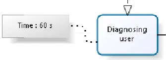
To map time constraint elements like what illustrated in figure (3), consider separate processes for timer path and message path, and combine the two processes using timeout[t] operation.
For each exclusive event-based gateway which events are timer and message:
Create process Timer_Path(); Create process Message_Path().
Begin Message_Path() with reading from channel;
Compose Timer_Path() and Message_Path() using timeout[Timer_time] operation;
Figure 2: Activity Time
V. EVALUATING CSP EXPRESSIONS PRODUCED BY SUGGESTED MAPPING
ALGORITHM
1. Goal Reachability test 2. Deadlock Free test 3. Divergence Free test 4. Time test
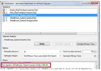
The aim of goal reachability test (figure (4)) is to ensure that all the intended steps in a process will be passed. To reach this aim we should declare a global variable and increase it in every step. At the end of process value of the variable should be equal to the number of steps.
In the exhaustive search method, all the possible paths will be checked not lead to deadlock. If any paths found that leads to deadlock, deadlock verification would not be valid (figure (5)).
The aim of divergence free test (figure (6)) is to evaluate the model not to have unpredictable and uncontrollable behaviors. Getting into an infinite loop or reaching different results from the primary purpose and so on, will be checked in the divergence free test.
For time test (figure (7)) we used a combination of goal reach ability test and timeout operation. We considered a deadline for the whole of the system (deadline[] operation) as a new process and performed the goal reachability test again.
Figure 4: Goal Reach Ability Test
Figure 5: Deadlock Free Test
Figure 6: Divergence Free Test
In this research, we’ve extended BPMN diagram to add time and have derived a mapping from BPD to Probabilistic Real-time CSP, to be a basic formal model for software development. People who need to evaluate their software formally can use our method to model their software in CSP. This is a basic model to modeling different software characteristics. As mentioned above, because of many challenges in today’s healthcare arena and also the clear vision of the future, we’ve chosen our business process case study from this domain. To do that, we wrote a CSP expression for each basic BPMN element and built bigger processes and presented a structure for communicating processes. We evaluated our method on a case study in the healthcare domain. We would like to extend it to include more details of BPMN elements and mapping in the future. We also would like to automate this mapping method to escape the modeling of business processes manually. Formal mathematical proofing of this mapping method can be our future research too.
REFERENCES
[1] Quan Z. Sheng, Xiaoqiang Qiao, Athanasios V. Vasilakos, Claudia Szabo, Scott Bourne, Xiaofei Xu, 2014, “Web services Composition: A decade’s overview”, Elsevier, Information Sciences.
[2] Oana-Sorina Lupşe, Mihaela Marcella Vida, Lăcrămioara Stoicu-Tivadar, 2012 , “Cloud Computing and Interoperability in Healthcare Information Systems”, INTELLI: The First International Conference on Intelligent Systems and Applications.
[3] Upkar Varshney, 2005, “Pervasive Heaithcare: Applicattions, Challenges and Wireless Solutions”, Communications of the Association for Information Systems, Volume 16, 57-72.
[4] Stephen A. White, 2016, “Process Modeling Notations and Workflow Patterns”, IBM Corp..
[5] Jakob Freund, Bernd Rücker, 2014, “Real-Life BPMN: Using BPMN 2.0 to Analyze, Improve, and Automate Processes in Your Company”.
[6] Stephen A. White, 2016, “BPMN Modeling and Reference Guide: Understanding and Using BPMN”, Future Strategies Inc.
[7] Andreas Lanz, Manfred Reichert, Barbara Weber, 2015, “Process time patterns: A formal foundation”, Elsevier, Information Systems.
[8] Saoussen Cheikhrouhou, Slim Kallel, Nawal Guermouche, Mohamed Jmaiel, 2015, “The Temporal
Eddine El Mohajir, , 2014, “Towards Formal Verification of Business Process using a Graphical Specification”, IEEE.
[10] Guisheng Fan, Huiqun Yu, Liqiong Chen, Dongmei Liu, 2014, “Formal Modeling and Analyzing the Reliability for Service Composition”, IEEE.
[11] Ali Rezaee, Amir Masoud Rahmani, Ali Movaghar, Mohammad Teshnehlab, 2014, “Formal process algebraic modeling, verification, and analysis of an abstract Fuzzy Inference Cloud Service”, Springer Science, J Supercomput 67:345–383.
[12] Matthew Rodano, Kristin Giammarco, 2013, “A Formal Method for Evaluation of a Modeled System Architecture”, Computer Science 20, 210–215, Conference Organized by Missouri University of Science and Technology.
[13] W. Ait-Cheik-Bihi, A. Nait-Sidi-Moh, M. Bakhouya, J. Gaber, M. Wack, 2012, “Performance Study of Workflow Patterns-Based Web Service Composition”, Elsevier.
[14] C. Dumez, M. Bakhouya, J. Gaber, M. Wack, P. Lorenz, 2013, “Model-driven approach supporting formal verification for web service composition protocols”, Elsevier Ltd, Journal of Network and Computer Applications 36, 1102–1115.
[15] A.W. Roscoe, 2005, “The Theory and Practice of Concurrency”.
[16] Hoare CAR, 2004, “Communicating sequential processes”, Prentice Hall, Englewood Cliffs.
[17] Minggang Yu, Zhixue Wang, and Xiaoxing Niu, 2016 , “Verifying Service Choreography Model Based on Description Logic”, Mathematical Problems in Engineering Volume 2016.
[18] Boumaza Amel, Maamri Ramedane, 2016, “From OWL-S to Timed Automata Network: Operational Semantic”, Procedia Computer Science Volume 83, 409-416.
[19] VineetPadmanabhan, Gopal N.Rai,.G.R. Gangadharan, 2015, “Algebraic Modeling and Verification of Web Service Composition”, Elsevier, Procedia Computer Science, Volume 52, 675-679.