INTRODUCTION
In the course of its deformation, materials may become separated into parts, which can oc-cur in two different ways [1, 2]:
• as brittle fracture – metal cohesion is broken due to rupture of atomic bonds;
• as ductile fracture – plastic strains occur with-out breaking metal cohesion.
It is worth stressing the fact that metal fracture is always preceded by strains.In terms of elastic stresses, even when material undergoes cracking, plastic strains occur near the surface of material separation known as fracture.
In terms of stress, the condition of brittle frac-ture can be expressed as:
σz = R0 (1)
where: R0 is the cohesive strength of material, σz is the reduced stress calculated from effort hy -potheses, e.g.: maximal principal stress (σz= σ1) or maximal elastic elongation (σz= σ1 – ν(σ2 + σ3)).
What may occur during the forming of metals and their alloys is ductile fracture that describes the potential forming limit in a given metal
form-ing process. Ductile fracture results from the change in material energy due to the accumula-tion of plastic strains causing fracture,which can be described with the expression (known as the damage criterion):
∫ 𝛷𝛷(𝜎𝜎)𝑑𝑑𝑑𝑑 = 𝐶𝐶𝜀𝜀𝑓𝑓
0 ,
(2)
where: Φ(σ) is the function describingthe effect of stress on the rate of formation and connection of cavities,εfis the limit strain, C is the limit val-ue of the damage function.
An overview of the literature [3-10] reveals that there is a number of ductile fracture criteria that are based on the function Φ(σ). The most important of these criteria are listed in Table 1, of which the last two (11) and (12) refer to the problem of ductile fracture in the aspect of stress and strain.
The practical use of the fracture criteria listed in Table 1, incorporated into many commercial computer simulation programmes, requires the knowledge of limit values of the damage func-tion C. These values are determined by means of tensile, compression or torsion tests performed Volume 12, Issue 4, December 2018, pages 184–189
https://doi.org/10.12913/22998624/100398
The Problem of Material Fracture Prediction
in Cross Rolling Processes
Zbigniew Pater
1, Janusz Tomczak
1, Tomasz Bulzak
1*, Andrzej Zniszczyński
11 Department of Computer Modelling and Metal Forming Technologies, Lublin University of Technology, ul.
Nadbystrzycka 36, 20-618 Lublin, Poland
* Corresponding author’s e-mail: [email protected]
ABSTRACT
The paper deals with the problem of material fracture prediction in metal forming processes. It was found that the application of well-established solutions for ductile fracture prediction to the modelling of cross rolling processes leads to serious errors. These errors result from the fact that the limit value of the damage function determined via uniaxial tensile and compression tests is too low. Therefore, it is necessary to devise a new test in which the state of stress is similar to that in a cross wedge rolling process characterized by the occurrence of alternating compres-sive and tensile stresses.
Keywords: material fracture, cross rolling, FEM
Research Journal
Accepted: 2018.11.05on specimens with specially designed shapes (axisymmetric or flat) to accelerate fracture of the material.
The research conducted by many scientists demonstrates that fracture depends not only on grain size, temperature and strain rate [3, 11-13], but on the state of stress described by a strain history as well [5, 14-17]. The main conclusion drawn from the results is that the fracture crite-rion is well-suited for the modelling of material fracture provided that the stresses in the test and the investigated process are similar.Given the need to come up with a universal solution,limit values of the damage function began to be deter-mined by a variety of tests,i.e., for different states of stress, e.g. stress triaxiality T = σm⁄σi. These values are then plotted as workability diagrams. Such diagrams are best suitedwhen investigating sheet forming – assuming the plane state of stress, they serve for drawing so-called forming limit di-agrams. Limit values are usually determined by the Nakajima test performed in compliance with a relevant ISO standard [14, 18].This can also be done using the Erichsen cupping test [3] or the
tensile test performed on flat specimens with side undercuts of different sizes [19].Thereby obtained data can be implemented into specialist computer software and effectively used to investigate sheet forming processes such as blanking, bending and press forming [4, 6, 9, 13, 14, 20-24].
The metal forming of solids requires more complex analyses. Limit damage functions are determined here by tensile and compressive tests of axisymmetric specimens and are often aver-aged [15]. A significant problem with hot com -pression tests concerns the determination of frac-ture initiation moment. The moment is difficult to determine because of strong thermal radiation that hampers recording the test with a camera [25]. This leads to a lower accuracy of material fracture prediction.For this reason, the number of scientific publications devoted to the problem of material fracture in metal forming processes for solids is considerably smaller than that on sheet forming. In this context one can enumerate stud-ies on cold metal forming processes by forging [26-28], extrusion [4], drawing [29].
It is very difficult to analyse the cases of forming in which the stresses cyclically change from tensile to compressive, and vice versa. Such states are characteristic of cross rolling processes (used for producing stepped shafts and axes and for forming screw threads and gear teeth) and skew rolling processes (used for producing tubes, balls for grinding media, rolling elements for bearings). In these processes, the stresses can lead to fracture in the central region of the workpiece [30-32]. The use of constant limit values deter -mined by tensile or compression tests does not yield correct results. To prove the above thesis, an analysis was performed. A detailed description of the analysis and its findings are given below.
DETERMINATION OF THE LIMIT VALUE
OF THE COCKROFT-LATHAM DAMAGE
FUNCTION
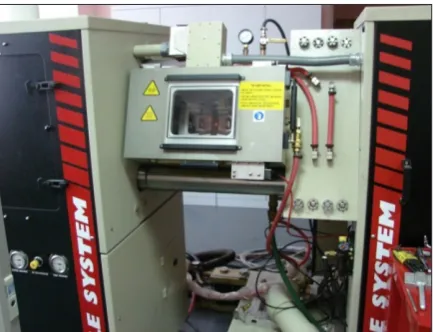
First of all, the limit damage function for C45 steel was determined in compliance with the Cockroft-Latham criterion in a tensile test for axi-symmetric specimens that was performed under hot metal forming conditions. Experimental tests were performed on the thermal-mechanical simu-lator Gleeble 3800, available at the Częstochowa University of Technology. The axisymmetric specimens used in the experiments had a
diam-Table 1. Selected damage functions used in ductile
fracture analysis [3-10]
Criterion Formula No
Freudenthal (3)
Cockroft & Latham (4)
Brozzo et al. (5)
Ayada (6)
Oyane (7)
Zhan et al. (8)
Rice & Tracey (9)
Norris et al. (10)
Gosh (11)
Datsko (12)
where: – critical plastic strain at fracture, – equivalent
stress, – mean stress, – maximal principal stress,
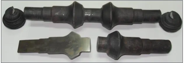
eter of 10 mm and a length of 116.5 mm, and were screwed on both sides (Figure 1). In their central region, the specimens had necking to facilitate the locating of strains. Prior to putting them in the simulator, the specimens were fixed in the tools and provided with a thermocouple to enable tem-perature measurements during the test. The ten-sion test was performed in the following way: the specimens were heated to the test temperatures (900°C, 1000°C, 1100°C and 1200°C) at a veloc -ity of 10°C/s (Figure 2); they were maintained at the target temperature for 5 s; the specimens were then subjected to tension at a tool velocity of 5 mm/s until fracture; finally, the specimens were removed from the machine. After the test, the fractured specimens were subjected to visual in-spection (Figure 3). Then, the value of elongation of specimen fracture was determined. The dam-age function value was determined numerically by the finite element method.
The average limit value of the integral versus temperature is shown in Figure 4. The data given in the figure demonstrate that the limit values of the damage function depend on temperature. The trend line (marked in red in Figure 4) shows a slight decrease in the function’s value with an increase in the temperature. In the uniaxial tensile test parameter σ1/σi = 1 and does not depend on the temperature. The value of the integral C-L in this
case depends only on the value of the critical plas-tic strain at fracture. Value of criplas-tical strain should be increase with an increasing in thetemperature. In connection with the above the obtained results shown in Figure 4 should be repeated in a differ -ent method. However most FEM-based computer simulation programmes (including DEFORM-3D, Simufact.Forming, Forge) allows for enter-ing only one limit value of the integral. Given this, it was considered necessary to determine the value of C2 for the entire hot forming temperature range (900–1200°C) for C45 steel. The value of C2 ranged 0.756 ± 0.125.
ANALYSIS OF A ROLLING PROCESS
FOR PRODUCING A DRIVE SHAFT WITH
RESPECT TO MATERIAL CRACKING
Further on, a cross wedge rolling process for producing a drive shaft shown in Figure 5 was analyzed. A detailed account of the analysis is given in [33]. Such a shaft can be formed using either single or double configuration. The latter solution is more effective as it ensures: 1) twice higher efficiency; 2) reduced material losses; 3) lower energy consumption to produce the shaft; 4) lower probability of crack formation inside the shaft.
Fig. 1. Shape of specimen used in tension tests and its basic dimensions
Fig. 2. Tension test performed under hot metal forming conditions
Fig. 3. Steel R200 specimens failure in tension test at temperature of: 1 - 900°C, 2 - 1000°C, 3 - 1100°C,
Figure 6 shows the geometrical model of a cross wedge rolling process for producing a drive shaft using double configuration. The model was created with the FEM-based Simu-fact.Forming computer software. The model was used to simulate this process numerically. The rolling process was based on the following as-sumptions: the upper tool moves with a velocity of 300 mm/s, while the lower toolis stationary; the model of the billet is assigned the properties of C45 steel obtained from the material database of the software used; prior to rolling, the billet is heated to a temperature of 1150°C; the tem
-perature of the tools is maintained constant at 50°C; the limit value of the friction factor on the material-tool surface is set to 1.0; the coefficient of heat transfer between tools and workpiece is set to 10 kW/m2K.
The numerical results provided a great deal of information about the investigated forming process, including the distributions of the tem-perature and the damage function, shown in Fig-ure 7.The results demonstrate that the tempera-ture of the shaft is within the hot forming range, while in the axial zone itranges 950°C÷1000°C. Therefore, material fracture in this process can be predicted based on the data givenin Figure 4. An analysis of the damage function (measured according to the Cockroft-Latham criterion) shown in Figure 7 demonstrates thatin the cen-tral region (shaft-connecting element), the func-tion exceeds 1.05, while in the side regions (the smallest diameter end step of the shaft) its value is even over 1.2.In these regions of the shaft, the fracture results from the fact that the limit value of the damage function has been exceeded (C2 = 0.756 ± 0.125).
The rolling tests conducted under laboratory conditions at the Lublin University of Technol-ogy, using the same parameters as in the numeri-cal simulation, led to producing drive shafts that are shown in Figure 8. However, the results of destructive tests consisting in uncovering of the axial section of the shafts reveal that the shafts are free from any internal cracks.This means that the limit values of the damage function obtained from the tensile test cannot be used to investigate cross rolling and skew rolling processes.
In light of the above, it is fully justified to de -velop new research methods for determining limit values of the damage function under changing loads that are typical of cross wedge rolling and skew rolling processes. In these processes, the stresses in the axial zone of the rotated workpiece alternately change from tensile to compressive (two times per one revolution of the workpiece). One of such methods is an innovative rotary com-pression test developed by Z. Pater. The method has been granted patent protection with the Patent Office of the Republic of Poland [34, 35].
CONCLUSIONS
The paper dealt with the problem of predict-ing the moment of material fracture in cross
roll-Fig. 4. Limit value of Cockroft-Latham integral for
C45 steel grade vs. temperature
Fig. 5. Drive shaft used in helicopters
Fig. 6. Geometrical model of cross wedge rollingfor
ing processes.The numerical results led to the fol-lowing conclusions:
1. The moment of material fracture in cross wedge rolling processes can be determined via the well-established criteria for ductile fracture prediction, the most important of which are specified in Table 1.
2. Limit values of the damage function should not be determined by standard tensile and com-pression tests, as in the case of cross rolling processes – these tests produce wrong results. 3. It is necessary to devise a new test for
deter-mining the limit damage function, in which the state of stress will be similar to that occurring in cross and skew rolling processes. The rotary compression test developed at the Lublin Uni-versity of Technology seems to be well-suited for this purpose.
Acknowledgements
The research has been conducted under the project No. 2017/25/B/ST8/00294 financed by the National Science Centre, Poland.
REFERENCES
1. Pater Z. and Samołyk G. Podstawy teorii i analizy
obróbki plastycznej metali. Wydawnictwo
Po-litechniki Lubelskiej, 2011.
2. Gabryszewski Z. and Gronostajski J. Mechanika
procesów obróbki plastycznej. PWN, 1991.
3. Kim S.W. and Lee Y.S. Comparative study on fail-ure prediction in warm forming processes of Mg alloy sheet by the FEM and ductile fracture
crite-ria. Metallurgical and Materials Transactions B,
45(2), 2014, 445-453.
4. Li H., Fu M.W., Lu J. and Yang H. Ductile fracture:
Experiments and computations. International
Jour-nal of Plasticity, 27(2), 2014, 147-180.
5. Yan Y., Wang H. and Wan M. Prediction of frac-ture in press bend forming of aluminum alloy
high-stiffener integral panels. Computational Materials Science, 50(7), 2011, 2232-2244.
6. Wu Z., Li S., Zhang W. and Wang W. Ductile frac-ture simulation of hydropiercing process based on various criteria in 3D modeling. Materials and
De-sign, 31(8), 2010, 3661-3671.
7. Otzurk F. and Lee D. A new methodology for duc-tile fracture criteria to predict the forming limits. Journal of Materials Engineering and Performance,
62(2), 2007, 224-228.
Fig. 7. Numerically determined temperature (top) and damage function according to Cockroft-Latham criterion
(bottom) in longitudinal section of drive shafts produced by rolling using double configuration
8. Otzurk F. and Lee D. Analysis of forming limits using ductile fracture criteria. Journal of Materials
Processing Technology, 147(3), 2004, 397-404. 9. Hambli R. and Reszka M. Fracture criteria
iden-tification using an inverse technique method and
blanking experiment. International Journal of
Me-chanical Sciences, 44(7), 2002, 1349-1361.
10. Kraisnik M., Vilotic D., Sidanin L. and Stefanovic
M. Various approaches to defining the criteria of
ductile crack in cold bulk forming processes. Annals of Faculty Engineering Hunedoara – International
Journal of Engineering, 13(2), 2015, 213-218.
11. Wang Z., Sun S., Wang B., Shi Z. and Fu W. Impor
-tance and role of grain size in free surface cracking prediction of heavy forgings. Materials Science &
Engineering A, 625(2), 2015, 321-330.
12. Novella M.F., Ghiotti A., Bruschi S. and Bariani
P.F. Ductile damage modeling at elevated
tempera-ture applied to the cross wedge rolling of
AA6082-T6 bars. Journal of Materials Processing Technol
-ogy, 222(8), 2015, 259-267.
13. Kim H.K. and Kim W.J. Failure prediction of mag-nesium alloy sheets deforming at warm tempera-tures using the Zener-Holloman parameter.
Me-chanics of Materials, 42(3), 2010, 293-303.
14. Bjorklund O., Govik A. and Nilsson L. Prediction
of fracture in a dual-phase steel subjected to non-linear straining. Journal of Materials Processing
Technology, 214(11), 2014, 2748-2758.
15. Yu S. and Feng W. Experimental research on duc-tile fracture criterion in metal forming. Frontiers of
Mechanical Engineering, 6(3), 2011, 308-311. 16. Coppola T., Cortese L. and Folgarait P. The
ef-fect of stress invariants on ductile fracture limit
in steels. Engineering Fracture Mechanics, 76(9), 2009, 1288-1302.
17. Goijarets A.M., Govaert L.E. and Baaijens F.P.T. Evaluation of ductile fracture models for different
metals in blanking. Journal of Materials Processing
Technology, 110(3), 2001, 312-323.
18. Bjorklund O., Larsson R. and Nilsson L. Failure of
high strength steel sheets: Experiments and model
-ling. Journal of Materials Processing Technology,
213(7), 2013, 1103-1117.
19. Dunand M. and Mohr D. Hybrid experimental-numerical analysis of basic ductile fracture ex-periments for sheet metals. International Journal of
Solids and Structures, 47(9), 2010, 1130-1143. 20. Yu S. and Zhao J. Investigation on blanking of thick
sheet metal using the ductile fracture initiation and propagation criterion. Journal of Shanghai Jiaotong
University (Science), 17(5), 2012, 531-536.
21. Cesar de Sa J.M.A., Areias P.M.A. and Zheng C. Damage modelling in metal forming problems
us-ing an implicit non-local gradient model. Comput-er Methods in Applied Mechanics and EngineComput-er-
Engineer-ing, 195(48-49), 2006, 6646-6660.
22. Kim J., Kim S.W., Song W.J. and Kang B.S. Analyt
-ical and numer-ical approach to prediction of form-ing limit in tube hydroformform-ing. International Journal
of Mechanical Sciences, 47(7), 2005, 1023-1037. 23. Lee Y.W. and Wierzbicki T. Fracture prediction of
thin plates under localized impulsive loading. Part
II: discing and petalling. International Journal of Impact Engineering, 31(10), 2005, 1277-1308. 24. Takuda H., Mori K. and Hatta N. The application
of some criteria for ductile fracture to the predic-tion of the forming limit of sheet metals. Journal of
Materials Processing Technology, 95(1-3), 1999, 116-121.
25. Zhu Y., Zeng W., Zhang F., Zhao Y., Zhang X. and Wang K. A new methodology for prediction of fracture initiation in hot compression of Ti40 tita-nium alloy. Materials Science and Engineering A,
553(9), 2012, 112-118.
26. Watanabe A., Fujikawa S., Ikeda A. and Shiga N. Prediction of ductile fracture in cold forging.
Pro-cedia Engineering, 81, 2014, 425-430.
27. Landre J., Pertence A., Cetlin P.R., Rodrigues J.M.C. and Martins P.A.F. On the utilization of duc-tile fracture criteria in cold forging. Finite Elements
in Analysis and Design, 39(3), 2003, 175-186. 28. MacCormack C. and Monaghan J. Failure analysis
of cold forging dies using FEA. Journal of Materials
Processing Technology, 117(1-2), 2001, 209-215. 29. Venkata R.N., Dixit P.M. and Lal G.K. Ductile
fracture criteria and its prediction in axisymmetric drawing. International Journal of Machine Tools &
Manufacture, 40(1), 2000, 95-111.
30. Pater Z. Cross-wedge rolling. In Comprehensive
Materials Processing. Ed., Elsevier Ltd., 2014.
31. Lu L., Wang Z. and Wang F. Simulation of tube forming process in Mannesmann mill. Journal of
Shanghai Jiaotong University (Science), 16(3), 2011, 281-185.
32. Ghiotti A., Fanini S., Bruschi S. and Bariani P.F. Modelling of Mannesmann effect. CIRP Annals – Manufacturing Technology, 58(1), 2009, 255-258.
33. Pater Z., Tomczak J. and Bulzak T. Analysis of a
cross wedge rolling process for producing drive shafts. The International Journal of Advanced
Man-ufacturing Technology,94(9-12), 2018, 3075-3083.
34. Pater Z. Sposób wyznaczania właściwości plasty
-cznych materiałów metodą obciskania obrotowego narzędziami płaskimi. Patent RP No 220786, 2014.
35. Pater Z. Sposób wyznaczania własności plastyc
![Table 1. Selected damage functions used in ductile fracture analysis [3-10]](https://thumb-us.123doks.com/thumbv2/123dok_us/8805971.1774575/2.595.70.289.93.385/table-selected-damage-functions-used-ductile-fracture-analysis.webp)