DAQ M Series
NI USB-621
x
User Manual
Bus-Powered M Series USB Devices
NI USB-621x User Manual
ni.com/manuals
ni.com
National Instruments Corporate Headquarters
11500 North Mopac Expressway Austin, Texas 78759-3504 USA Tel: 512 683 0100
Worldwide Offices
Australia 1800 300 800, Austria 43 662 457990-0, Belgium 32 (0) 2 757 0020, Brazil 55 11 3262 3599, Canada 800 433 3488, China 86 21 5050 9800, Czech Republic 420 224 235 774, Denmark 45 45 76 26 00, Finland 358 (0) 9 725 72511, France 01 57 66 24 24, Germany 49 89 7413130, India 91 80 41190000, Israel 972 3 6393737, Italy 39 02 41309277, Japan 0120-527196, Korea 82 02 3451 3400,
Lebanon 961 (0) 1 33 28 28, Malaysia 1800 887710, Mexico 01 800 010 0793, Netherlands 31 (0) 348 433 466, New Zealand 0800 553 322, Norway 47 (0) 66 90 76 60, Poland 48 22 328 90 10, Portugal 351 210 311 210, Russia 7 495 783 6851, Singapore 1800 226 5886, Slovenia 386 3 425 42 00, South Africa 27 0 11 805 8197, Spain 34 91 640 0085, Sweden 46 (0) 8 587 895 00, Switzerland 41 56 2005151, Taiwan 886 02 2377 2222, Thailand 662 278 6777, Turkey 90 212 279 3031, United Kingdom 44 (0) 1635 523545
Important Information
Warranty
The NI USB-6210, NI USB-6211, NI USB-6212, NI USB-6215, NI USB-6216, and NI USB-6218 are warranted against defects in materials and workmanship for a period of one year from the date of shipment, as evidenced by receipts or other documentation. National Instruments will, at its option, repair or replace equipment that proves to be defective during the warranty period. This warranty includes parts and labor. The media on which you receive National Instruments software are warranted not to fail to execute programming instructions, due to defects in materials and workmanship, for a period of 90 days from date of shipment, as evidenced by receipts or other documentation. National Instruments will, at its option, repair or replace software media that do not execute programming instructions if National Instruments receives notice of such defects during the warranty period. National Instruments does not warrant that the operation of the software shall be uninterrupted or error free.
A Return Material Authorization (RMA) number must be obtained from the factory and clearly marked on the outside of the package before any equipment will be accepted for warranty work. National Instruments will pay the shipping costs of returning to the owner parts which are covered by warranty.
National Instruments believes that the information in this document is accurate. The document has been carefully reviewed for technical accuracy. In the event that technical or typographical errors exist, National Instruments reserves the right to make changes to subsequent editions of this document without prior notice to holders of this edition. The reader should consult National Instruments if errors are suspected. In no event shall National Instruments be liable for any damages arising out of or related to this document or the information contained in it.
EXCEPTASSPECIFIEDHEREIN, NATIONAL INSTRUMENTSMAKESNOWARRANTIES, EXPRESSORIMPLIED, ANDSPECIFICALLYDISCLAIMSANYWARRANTYOF MERCHANTABILITYORFITNESSFORAPARTICULARPURPOSE. CUSTOMER’SRIGHTTORECOVERDAMAGESCAUSEDBYFAULTORNEGLIGENCEONTHEPARTOF NATIONAL INSTRUMENTSSHALLBELIMITEDTOTHEAMOUNTTHERETOFOREPAIDBYTHECUSTOMER. NATIONAL INSTRUMENTSWILLNOTBELIABLEFORDAMAGESRESULTING FROMLOSSOFDATA, PROFITS, USEOFPRODUCTS, ORINCIDENTALORCONSEQUENTIALDAMAGES, EVENIFADVISEDOFTHEPOSSIBILITYTHEREOF. This limitation of the liability of National Instruments will apply regardless of the form of action, whether in contract or tort, including negligence. Any action against National Instruments must be brought within one year after the cause of action accrues. National Instruments shall not be liable for any delay in performance due to causes beyond its reasonable control. The warranty provided herein does not cover damages, defects, malfunctions, or service failures caused by owner’s failure to follow the National Instruments installation, operation, or maintenance instructions; owner’s modification of the product; owner’s abuse, misuse, or negligent acts; and power failure or surges, fire, flood, accident, actions of third parties, or other events outside reasonable control.
Copyright
Under the copyright laws, this publication may not be reproduced or transmitted in any form, electronic or mechanical, including photocopying, recording, storing in an information retrieval system, or translating, in whole or in part, without the prior written consent of National Instruments Corporation.
National Instruments respects the intellectual property of others, and we ask our users to do the same. NI software is protected by copyright and other intellectual property laws. Where NI software may be used to reproduce software or other materials belonging to others, you may use NI software only to reproduce materials that you may reproduce in accordance with the terms of any applicable license or other legal restriction.
Trademarks
National Instruments, NI, ni.com, and LabVIEW are trademarks of National Instruments Corporation. Refer to the Terms of Use section onni.com/legal for more information about National Instruments trademarks.
Other product and company names mentioned herein are trademarks or trade names of their respective companies.
Members of the National Instruments Alliance Partner Program are business entities independent from National Instruments and have no agency, partnership, or joint-venture relationship with National Instruments.
Patents
For patents covering National Instruments products/technology, refer to the appropriate location: Help»Patents in your software, thepatents.txt file on your media, or the National Instruments Patent Notice at ni.com/patents.
WARNING REGARDING USE OF NATIONAL INSTRUMENTS PRODUCTS
(1) NATIONAL INSTRUMENTS PRODUCTS ARE NOT DESIGNED WITH COMPONENTS AND TESTING FOR A LEVEL OF RELIABILITY SUITABLE FOR USE IN OR IN CONNECTION WITH SURGICAL IMPLANTS OR AS CRITICAL COMPONENTS IN ANY LIFE SUPPORT SYSTEMS WHOSE FAILURE TO PERFORM CAN REASONABLY BE EXPECTED TO CAUSE SIGNIFICANT INJURY TO A HUMAN.
About This Manual
Conventions ...xiii Related Documentation...xiv
Chapter 1
Getting Started
Installing NI-DAQmx ...1-1 Installing Other Software...1-1 Installing the Hardware...1-1 Device Self-Calibration ...1-2 Device Pinouts ...1-2 Device Specifications ...1-2 Applying Signal Labels to the USB-621x...1-3
USB Cable Strain Relief ...1-4 Mounting the USB-621x...1-6
Desktop Use...1-6 DIN Rail Mounting...1-6 Panel Mounting ...1-7 USB Device Security Cable Slot ...1-8
Chapter 2
DAQ System Overview
Chapter 3
Connector and LED Information
I/O Connector Signal Descriptions... 3-1 +5 V Power... 3-3 +5 V Power as an Output ... 3-3 +5 V Power as an Input... 3-3 USB Chassis Ground... 3-4 USB Device Fuse Replacement... 3-4 PWR/ACT LED Indicator ... 3-6
Chapter 4
Analog Input
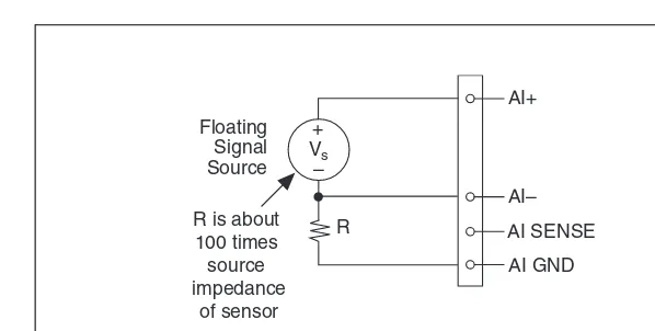
Getting Started with AI Applications in Software...4-22 Connecting Analog Input Signals on USB-6210/6211/6212 Devices...4-23 Connecting Floating Signal Sources ...4-25 What Are Floating Signal Sources? ...4-25 When to Use Differential Connections with
Floating Signal Sources...4-25 When to Use Referenced Single-Ended Connections with
Floating Signal Sources...4-25 When to Use Non-Referenced Single-Ended Connections with
Floating Signal Sources...4-26 Using Differential Connections for Floating Signal Sources...4-27 Using Non-Referenced Single-Ended Connections for
Floating Signal Sources...4-30 Using Referenced Single-Ended Connections for
Floating Signal Sources...4-31 Connecting Ground-Referenced Signal Sources ...4-31 What Are Ground-Referenced Signal Sources?...4-31 When to Use Differential Connections with
Ground-Referenced Signal Sources ...4-32 When to Use Non-Referenced Single-Ended Connections with
Ground-Referenced Signal Sources ...4-32 When to Use Referenced Single-Ended Connections with
Ground-Referenced Signal Sources ...4-33
Using Differential Connections for Ground-Referenced
Signal Sources ...4-34 Using Non-Referenced Single-Ended Connections for
Ground-Referenced Signal Sources ...4-35 Connecting Analog Input Signals on USB-6215/6216/6218 Devices...4-36 Taking Differential Measurements...4-36 Taking Referenced Single-Ended Measurements ...4-37 Taking Non-Referenced Single-Ended Measurements ...4-38
Chapter 5
Analog Output
AO Pause Trigger Signal ... 5-6 Using a Digital Source... 5-7 AO Sample Clock Signal ... 5-8 Using an Internal Source ... 5-8 Using an External Source ... 5-8 Routing AO Sample Clock to an Output Terminal ... 5-8 Other Timing Requirements ... 5-8 AO Sample Clock Timebase Signal... 5-9 Getting Started with AO Applications in Software ... 5-10
Chapter 6
Digital I/O
Digital I/O on USB-6210/6211/6215/6218 Devices ... 6-1 Static DIO on USB-6210/6211/6215/6218 Devices ... 6-2 I/O Protection on USB-6210/6211/6215/6218 Devices... 6-2 Increasing Current Drive on USB-6210/6211/6215/6218 Devices ... 6-3 Connecting Digital I/O Signals on USB-6210/6211/6215/6218 Devices... 6-3 Getting Started with DIO Applications in Software on
USB-6210/6211/6215/6218 Devices ... 6-4 Digital I/O on USB-6212/6216 Devices... 6-4 Static DIO on USB-6212/6216 Devices ... 6-5 I/O Protection on USB-6212/6216 Devices... 6-5 Programmable Power-Up States on USB-6212/6216 Devices ... 6-6 Increasing Current Drive on USB-6212/6216 Devices... 6-6 Connecting Digital I/O Signals on USB-6212/6216 Devices ... 6-6 Getting Started with DIO Applications in Software on
USB-6212/6216 Devices... 6-7
Chapter 7
PFI
Chapter 8
Counters
Counter Input Applications...8-2 Counting Edges ...8-2 Single Point (On-Demand) Edge Counting ...8-2 Buffered (Sample Clock) Edge Counting ...8-3 Controlling the Direction of Counting ...8-4 Pulse-Width Measurement ...8-4 Single Pulse-Width Measurement...8-4 Buffered Pulse-Width Measurement...8-5 Period Measurement...8-6 Single Period Measurement ...8-6 Buffered Period Measurement ...8-7 Semi-Period Measurement ...8-8 Single Semi-Period Measurement...8-8 Buffered Semi-Period Measurement...8-9 Frequency Measurement ...8-10
Counter n Gate Signal ... 8-29 Routing a Signal to Counter n Gate... 8-29 Routing Counter n Gate to an Output Terminal ... 8-29 Counter n Aux Signal... 8-29 Routing a Signal to Counter n Aux ... 8-29 Counter n A, Counter n B, and Counter n Z Signals ... 8-30 Routing Signals to A, B, and Z Counter Inputs... 8-30 Counter n Up_Down Signal ... 8-30 Counter n HW Arm Signal... 8-30 Routing Signals to Counter n HW Arm Input ... 8-31 Counter n Internal Output and Counter n TC Signals... 8-31 Routing Counter n Internal Output to an Output Terminal ... 8-31 Frequency Output Signal ... 8-31 Routing Frequency Output to a Terminal... 8-31 Default Counter/Timer Pinouts ... 8-32 Counter Triggering ... 8-33 Other Counter Features... 8-34 Sample Clock ... 8-34 Cascading Counters... 8-35 Counter Filters... 8-35 Prescaling ... 8-36 Duplicate Count Prevention ... 8-37
Example Application That Works Correctly
(No Duplicate Counting) ... 8-37 Example Application That Works Incorrectly
(Duplicate Counting) ... 8-38 Example Application That Prevents Duplicate Count... 8-38 Enabling Duplicate Count Prevention in NI-DAQmx... 8-39
Chapter 9
Isolation and Digital Isolators on USB-6215/6216/6218 Devices
Chapter 10
Digital Routing and Clock Generation
80 MHz Timebase...10-1 20 MHz Timebase...10-1 100 kHz Timebase ...10-1
Chapter 11
Bus Interface
USB Signal Stream ...11-1 Data Transfer Methods ...11-1 Changing Data Transfer Methods ...11-2
Chapter 12
Triggering
Triggering with a Digital Source ...12-1
Appendix A
Device-Specific Information
USB-6210 ...A-2 USB-6211/6215 ...A-4 USB-6212/6216 Screw Terminal...A-6 USB-6212/6216 Mass Termination ...A-8 USB-6212/6216 BNC ...A-13 USB-6218 Screw Terminal...A-19 USB-6218 BNC ...A-21
Appendix B
Troubleshooting
Appendix C
Glossary
Index
Device Pinouts
The NI USB-621x User Manual contains information about using the National Instruments USB-621x data acquisition (DAQ) devices with NI-DAQmx 8.9 and later. NI USB-6210, USB-6211, USB-6212,
USB-6215, USB-6216, and USB-6218 devices feature up to 32 analog
input (AI) channels, up to two analog output (AO) channels, two counters, and up to eight lines of digital input (DI) and up to eight lines of digital output (DO), or 32 bidirectional static DIO lines.
Conventions
The following conventions are used in this manual:
<> Angle brackets that contain numbers separated by an ellipsis represent
a range of values associated with a bit or signal name—for example, AO <3..0>.
» The » symbol leads you through nested menu items and dialog box options
to a final action. The sequence File»Page Setup»Options directs you to pull down the File menu, select the Page Setup item, and select Options
from the last dialog box.
This icon denotes a note, which alerts you to important information.
This icon denotes a caution, which advises you of precautions to take to avoid injury, data loss, or a system crash.When this symbol is marked on a product, refer to the Read Me First: Safety and Electromagnetic
Compatibility documentfor information about precautions to take.
bold Bold text denotes items that you must select or click in the software, such
as menu items and dialog box options. Bold text also denotes parameter names.
monospace Text in this font denotes text or characters that you should enter from the keyboard, sections of code, programming examples, and syntax examples. This font is also used for the proper names of disk drives, paths, directories, programs, subprograms, subroutines, device names, functions, operations, variables, filenames, and extensions.
Platform Text in this font denotes a specific platform and indicates that the text following it applies only to that platform.
Related Documentation
Each application software package and driver includes information about writing applications for taking measurements and controlling measurement devices. The following references to documents assume you have
NI-DAQ 8.9 or later, and where applicable, version 7.1 or later of the NI application software.
NI-DAQmx for Windows
The NI-DAQmx for USB Devices Getting Started Guide describes
how to install your NI-DAQmx for Windows software, your
NI-DAQmx-supported DAQ device, and how to confirm that your device is
operating properly. Select Start»All Programs»National Instruments»
NI-DAQ»NI-DAQmx for USB Devices Getting Started.
The NI-DAQ Readme lists which devices are supported by this version of
NI-DAQ. Select Start»All Programs»National Instruments»NI-DAQ»
NI-DAQ Readme.
The NI-DAQmx Help contains general information about measurement concepts, key NI-DAQmx concepts, and common applications that are
applicable to all programming environments. Select Start»All Programs»
National Instruments»NI-DAQ»NI-DAQmx Help.
NI-DAQmx Base (Linux/Mac OS X/LabVIEW Mobile Module 8.
x
/
LabVIEW Touch Panel Module 8.
x
)
The NI-DAQmx Base Getting Started Guide describes how to install your
NI-DAQmx Base software, your NI-DAQmx Base-supported DAQ device,
and how to confirm that your device is operating properly. In Windows,
select Start»All Programs»National Instruments»NI-DAQmx Base»
Getting Started with NI-DAQmx Base for Linux and Mac Users describes
how to install your NI-DAQmx Base software, your NI-DAQmx
Base-supported DAQ device, and how to confirm that your device is operating properly on your Mac/Linux machine.
The NI-DAQmx Base Readme lists which devices are supported by this
version of NI-DAQmx Base. In Windows, select Start»All Programs»
National Instruments»NI-DAQmx Base»DAQmx Base Readme.
The NI-DAQmx Base VI Reference Help contains VI reference and general
information about measurement concepts. In LabVIEW, select Help»
NI-DAQmx Base VI Reference Help.
The NI-DAQmx Base C Reference Help contains C reference and general information about measurement concepts. In Windows, select Start» All Programs»National Instruments»NI-DAQmx Base»
Documentation»C Function Reference Help.
Note All NI-DAQmx Base documentation for Linux is installed at /usr/local/
natinst/nidaqmxbase/documentation.
Note All NI-DAQmx Base documentation for Mac OS X is installed at /Applications/
National Instruments/NI-DAQmx Base/documentation.
LabVIEW
If you are a new user, use the Getting Started with LabVIEW manual
to familiarize yourself with the LabVIEW graphical programming
Use the LabVIEW Help, available by selecting Help»Search the LabVIEW Help in LabVIEW, to access information about LabVIEW programming concepts, step-by-step instructions for using LabVIEW, and reference information about LabVIEW VIs, functions, palettes, menus, and tools. Refer to the following locations on the Contents tab of the LabVIEW
Help for information about NI-DAQmx:
• Getting Started with LabVIEW»Getting Started with
DAQ—Includes overview information and a tutorial to learn how to
take an NI-DAQmx measurement in LabVIEW using the DAQ
Assistant.
• VI and Function Reference»Measurement I/O VIs and
Functions—Describes the LabVIEW NI-DAQmx VIs and properties.
• Taking Measurements—Contains the conceptual and how-to information you need to acquire and analyze measurement data
in LabVIEW, including common measurements, measurement
fundamentals, NI-DAQmx key concepts, and device considerations.
LabWindows/CVI
The Data Acquisition book of the LabWindows/CVI Help contains
measurement concepts for NI-DAQmx. This book also contains Taking
an NI-DAQmx Measurement in LabWindows/CVI, which includes step-by-step instructions about creating a measurement task using the DAQ Assistant. In LabWindows™/CVI™, select Help»Contents, then select Using LabWindows/CVI»Data Acquisition.
The NI-DAQmx Library book of the LabWindows/CVI Help contains
API overviews and function reference for NI-DAQmx. Select Library
Reference»NI-DAQmx Library in the LabWindows/CVI Help.
Measurement Studio
If you program your NI-DAQmx-supported device in Measurement Studio
using Visual C++, Visual C#, or Visual Basic .NET, you can interactively
create channels and tasks by launching the DAQ Assistant from MAX or
from within Visual Studio .NET. You can generate the configuration code based on your task or channel in Measurement Studio. Refer to the DAQ Assistant Help for additional information about generating code. You also can create channels and tasks, and write your own applications in your
ADE using the NI-DAQmx API.
For help with NI-DAQmx methods and properties, refer to the NI-DAQmx
.NET Class Library or the NI-DAQmx Visual C++ Class Library included
in Measurement Studio, refer to the NI Measurement Studio Help, which is fully integrated with the Microsoft Visual Studio .NET help. To view this help file in Visual Studio. NET, select Measurement Studio» NI Measurement Studio Help.
To create an application in Visual C++, Visual C#, or Visual Basic .NET, follow these general steps:
1. In Visual Studio .NET, select File»New»Project to launch the New Project dialog box.
2. Find the Measurement Studio folder for the language you want to create a program in.
3. Choose a project type. You add DAQ tasks as a part of this step.
ANSI C without NI Application Software
The NI-DAQmx Help contains API overviews and general information
about measurement concepts. Select Start»All Programs»National
Instruments»NI-DAQmx Help.
The NI-DAQmx C Reference Help describes the NI-DAQmx Library functions, which you can use with National Instruments data acquisition devices to develop instrumentation, acquisition, and control applications.
Select Start»All Programs»National Instruments»NI-DAQ»
NI-DAQmx C Reference Help.
.NET Languages without NI Application Software
With the Microsoft .NET Framework version 1.1 or later, you can use NI-DAQmx to create applications using Visual C# and Visual Basic .NET without Measurement Studio. You need Microsoft Visual Studio .NET 2003 or Microsoft Visual Studio 2005 for the API documentation to be installed.
The installed documentation contains the NI-DAQmx API overview,
measurement tasks and concepts, and function reference. This help is fully integrated into the Visual Studio .NET documentation. To view the
NI-DAQmx .NET documentation, go to Start»Programs»National
Instruments»NI-DAQ»NI-DAQmx .NET Reference Help. Expand
NI Measurement Studio Help»NI Measurement Studio .NET Class Library»Reference to view the function reference. Expand
To get to the same help topics from within Visual Studio, go to Help» Contents. Select Measurement Studio from the Filtered By drop-down list and follow the previous instructions.
Device Documentation and Specifications
The NI USB-621x Specifications contains all specifications for the USB-6210, USB-6211, USB-6212, USB-6215, USB-6216, and USB-6218 M Series devices.
Documentation for supported devices and accessories, including PDF and help files describing device terminals, specifications, features, and
operation are on the NI-DAQmx media that includes Device
Documentation. Insert the media, open the Device Documentation directory, and double-click the Device Documents shortcut for your language to find, view, and print device documents.
Training Courses
If you need more help getting started developing an application with NI products, NI offers training courses. To enroll in a course or obtain a detailed course outline, refer to ni.com/training.
Technical Support on the Web
For additional support, refer to ni.com/support or zone.ni.com.
Note You can download these documents at ni.com/manuals.
DAQ specifications and manuals are available as PDFs. You must have Adobe Acrobat Reader with Search and Accessibility 5.0.5 or later installed to view the PDFs. Refer to the Adobe Systems Incorporated
Web site at www.adobe.com to download Acrobat Reader. Refer to the
National Instruments Product Manuals Library at ni.com/manuals for
1
Getting Started
NI USB-621x devices feature up to 32 analog input (AI) channels, up to two analog output (AO) channels, two counters, and up to eight lines of digital input (DI) and up to eight lines of digital output (DO), or 32 bidirectional static DIO lines.
Installing NI-DAQmx
The NI-DAQmx for USB Devices Getting Started Guide, which you can
download from ni.com/manuals, offers NI-DAQmx users step-by-step
instructions for installing software and hardware, configuring channels and tasks, and getting started developing an application.
Installing Other Software
If you are using other software, refer to the installation instructions that accompany your software.
Installing the Hardware
Device Self-Calibration
NI recommends that you self-calibrate your USB-621x device after installation and whenever the ambient temperature changes.
Self-calibration should be performed after the device has warmed up for the recommended time period. Refer to the NI USB-621x Specifications to find your device warm-up time. This function measures the onboard reference voltage of the device and adjusts the self-calibration constants to account for any errors caused by short-term fluctuations in the environment. Disconnect all external signals when you self-calibrate a device.
You can initiate self-calibration using Measurement & Automation Explorer (MAX), by completing the following steps.
1. Launch MAX.
2. Select My System»Devices and Interfaces»NI-DAQmx
Devices»your device.
3. Initiate self-calibration using one of the following methods:
• Click Self-Calibrate in the upper right corner of MAX.
• Right-click the name of the device in the MAX configuration tree
and select Self-Calibrate from the drop-down menu.
Note You can also programmatically self-calibrate your device with NI-DAQmx,
as described in Device Calibration in the NI-DAQmx Help or the LabVIEW Help in version 8.0 or later.
Device Pinouts
Refer to Appendix A, Device-Specific Information, for USB-621x device
pinouts.
Device Specifications
Refer to the NI USB-621x Specifications, available on the NI-DAQ Device
Documentation Browser or from ni.com/manuals, for more detailed
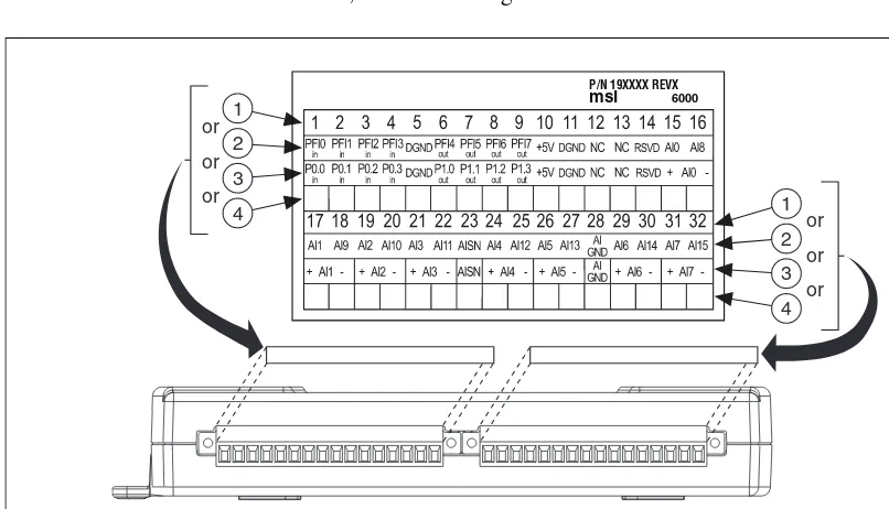
Applying Signal Labels to the USB-621
x
(USB-621x Screw Terminal Devices) Your USB-621x kit includes labels for
the combicon connectors on USB-621x Screw Terminal devices. You can
choose labels with pin numbers or signal names or blank labels. Choose one of the labels, align the correct label with the terminals printed on the top panel of your device or the 16-position combicon connector, and apply the label, as shown in Figure 1-1.
Figure 1-1. USB-621x Screw Terminal Signal Labels
1 Terminal Number Label
2 Single-Ended Signal Name Label
3 Differential Signal Name Label
4 User-Defined Custom Label
P/N 19XXXX REVX msi 6000
4
3
2 1 or
or
or
or
or
or 1
4
3
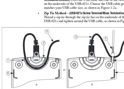
USB Cable Strain Relief
You can provide strain relief for the USB cable in the following ways:
• Cable Strain Relief Groove Method—(USB-621x Screw Terminal/Mass Termination Devices) Press the USB cable into one of the two grooves on the underside of the USB-621x. Choose the USB cable groove that matches your USB cable size, as shown in Figure 1-2a.
• Zip Tie Method—(USB-621x Screw Terminal/Mass Termination Devices) Thread a zip tie through the zip tie bar on the underside of the USB-621x and tighten around the USB cable, as shown in Figure 1-2b.
Figure 1-2. USB Cable Strain Relief Options on USB-621x Screw Terminal/Mass Termination Devices
1 USB Cable Strain Relief Groove (Large)
2 USB Cable Strain Relief Groove (Small)
3 USB Cable
4 Zip Tie
5 Zip Tie Bar
6 Stacking Groove
1
2
3
3
5 4
a b
or
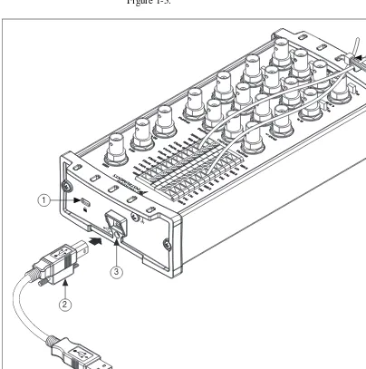
• Locking USB Cable Method—(USB-621x BNC Devices) Use the
jackscrew on the locking USB cable (included in the USB-621x
BNC kit) to securely attach the cable to the device, as shown in Figure 1-3.
Figure 1-3. USB Cable Strain Relief on USB-621x BNC Devices
Note You can provide cable management for signal wires to/from the screw terminals and
BNC connectors on USB-621x BNC devices by threading a zip tie through the strain relief holes and tightening it around the signal wires and BNC cables, as shown in Figure 1-3.
1 Security Cable Slot
2 Locking USB Cable Jackscrew
3 Jackscrew Hole
4 Signal Wire Strain Relief
1
2
3
Mounting the USB-621
x
You can use the USB-621x on a desktop or mount it to a standard DIN rail or a panel.
Desktop Use
You can use the USB-621x on a desktop. USB-621x Screw Terminal/Mass Termination devices have grooves on the underside that allow it to be stacked with other like-sized USB-621x devices, as shown in Figure 1-2.
Note USB-621x BNC devices cannot be stacked.
(USB-621x Screw Terminal/Mass Termination Devices) For secure desktop use, adhere the supplied rubber non-skid feet to the underside of the USB-621x
device, as shown in Figure 1-4.
Note Do not apply the rubber feet if you are panel mounting the USB-621x or stacking the
device on another USB-621x device.
Figure 1-4. Rubber Feet Application
DIN Rail Mounting
The DIN rail mounting kit (part number 779689-01, not included in your USB-621x kit) is an accessory you can use to mount the USB-621x family of products to a standard DIN rail.
Note Apply strain relief, as described in the USB Cable Strain Relief section, before
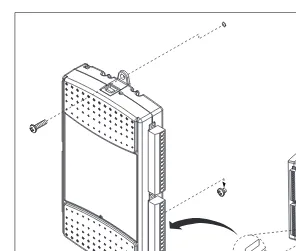
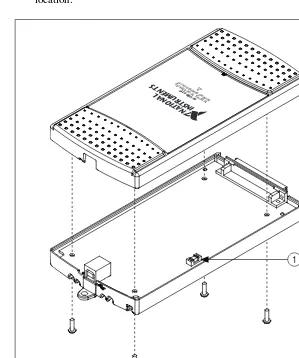
Panel Mounting
(USB-621x Screw Terminal/Mass Termination Devices) To mount the USB-621x
to a board or panel, complete the following steps while referring to Figure 1-5.
Figure 1-5. Mounting the USB-621x on a Panel
Note Do not apply the rubber feet to the USB-621x when panel mounting the device.
Note Apply strain relief, as described in the USB Cable Strain Relief section, before panel mounting the USB-621x.
1. Download and print the panel mounting template PDF attached in the
KnowledgeBase document, USB-621x Panel Mounting Template.
Go to ni.com/info and enter the info code ex3x98 to locate the KnowledgeBase.
2. Using the template, mark the bottom point and top point on the panel.
(USB-621x Screw Terminal Devices) The points will be 171.45 mm (6.75 in.) from each other.
3. Remove the USB cable from the connector on the USB-621x.
4. Screw a #8 or M4 screw into the bottom point on the panel.
5. Set the USB-621x on the screw by fitting it into the bottom screw notch on the underside of the USB-621x.
6. Screw a #8 or M4 screw through the USB-621x top screw hole into the panel.
USB Device Security Cable Slot
(USB-621x BNC Devices) The security cable slot, shown in Figure 1-3, allows you to attach an optional antitheft device to your USB device.
Note The security cable is designed to act as a deterrent, but might not prevent the device from being mishandled or stolen. For more information, refer to the documentation that accompanied the security cable.
Note The security cable slot on the USB-621x BNC might not be compatible with all
2
DAQ System Overview
Figure 2-1 shows a typical DAQ system, which includes the USB-621x
device, programming software, and PC (DAQ systems involving the
USB-621x Mass Termination device can also include signal conditioning
devices and a cable for accessory connection). The following sections
contain more information about the components of a typical DAQ system.
Figure 2-1. Components of a Typical DAQ System
DAQ Hardware
DAQ hardware digitizes signals, performs D/A conversions to generate analog output signals, and measures and controls digital I/O signals.
Personal Computer or Laptop DAQ
Hardware
DAQ Software Sensorsand
Transducers (USB-621x Mass Termination
Devices Only)
Signal Conditioning
(USB-621x Mass Termination
Devices Only)
Figure 2-2 features components common to all USB-621x devices.
Figure 2-2. USB-621x Block Diagram
DAQ-STC2
The DAQ-STC2 implements a high-performance digital engine for M Series data acquisition hardware. Some key features of this engine include the following:
• Flexible AI and AO sample and convert timing
• Many triggering modes
• Independent AI, AO, and CTR FIFOs
• Generation and routing of internal and external timing signals
• Two flexible 32-bit counter/timer modules with hardware gating
• Static DI, DO, and DIO signals
• USB Hi-Speed 2.0 interface
• Up to four USB Signal Streams for acquisition and generation functions
Calibration Circuitry
The USB-621x analog inputs and outputs have calibration circuitry to correct gain and offset errors. You can calibrate the device to minimize AI and AO errors caused by time and temperature drift at run time. No external circuitry is necessary; an internal reference ensures high accuracy and stability over time and temperature changes.
Analog Output
Digital I/O
Analog Input
Counters
PFI
Digital
Routing
and Clock
Generation
Bus
Interface Bus
I/O Connector
Digital
Isolators
Isolation
Barrier
(USB-6215/
6216/6218
Factory-calibration constants are permanently stored in an onboard
EEPROM and cannot be modified. When you self-calibrate the device,
software stores new constants in a user-modifiable section of the EEPROM. To return a device to its initial factory calibration settings, software can copy the factory-calibration constants to the user-modifiable section
of the EEPROM. Refer to the NI-DAQmx Help or the LabVIEW Help in
version 8.0 or later for more information about using calibration constants.
For a detailed calibration procedure for USB-621x devices, refer to the
B/E/M/S Series Calibration Procedure for NI-DAQmx by clicking
Manual Calibration Procedures on ni.com/calibration.
Signal Conditioning
Many sensors and transducers require signal conditioning before a measurement system can effectively and accurately acquire the signal. The front-end signal conditioning system can include functions such as signal amplification, attenuation, filtering, electrical isolation, simultaneous sampling, and multiplexing. In addition, many transducers require excitation currents or voltages, bridge completion, linearization, or high amplification for proper and accurate operation. Therefore, most computer-based measurement systems include some form of signal conditioning in addition to plug-in data acquisition DAQ devices.
Sensors and Transducers
Sensors can generate electrical signals to measure physical phenomena, such as temperature, force, sound, or light. Some commonly used sensors are strain gauges, thermocouples, thermistors, angular encoders, linear encoders, and resistance temperature detectors (RTDs).
To measure signals from these various transducers, you must convert them into a form that a DAQ device can accept. For example, the output voltage of most thermocouples is very small and susceptible to noise. Therefore, you may need to amplify or filter the thermocouple output before digitizing it. The manipulation of signals to prepare them for digitizing is called signal conditioning.
For more information about sensors, refer to the following documents:
• For general information about sensors, visit ni.com/sensors.
• If you are using LabVIEW, refer to the LabVIEW Help by selecting
• If you are using other application software, refer to Common Sensors
in the NI-DAQmx Help or the LabVIEW Help in version 8.0 or later.
Cables and Accessories
Cable and accessory options for USB-621x devices are as follows:
• Combicon Accessory for USB-621x Screw Terminal Devices (Optional)—Your USB-621x kit includes combicon connectors with signal labels. The NI USB-621x Accessory Kit (part number
779807-01) contains four combicon connectors with screws, a
screwdriver, and additional signal labels. You can use the combicon accessory to create custom connection solutions for USB-621x Screw Terminal devices.
• Cables and Accessories for USB-621x Mass Termination
Devices—Refer to the USB-6212/6216 Mass Termination Cables and Accessories section of Appendix A, Device-Specific Information, for a list of cables and accessories for USB-621x Mass Termination devices.
• BNC Cables for USB-621x BNC Devices—Use standard BNC cables
with the USB-621x BNC device. The BNC Male (Plug) to BNC Male
(Plug) Cables Kit (part number 779697-01) contains four one-meter
BNC cables for use with USB-621x BNC devices.
USB-621
x
Mass Termination Custom Cabling
NI offers cables and accessories for many applications. However, if you
want to develop your own cable, adhere to the following guidelines for best results:
• For AI signals, use shielded, twisted-pair wires for each AI pair of differential inputs. Connect the shield for each signal pair to the ground reference at the source.
• Route the analog lines separately from the digital lines.
• When using a cable shield, use separate shields for the analog and digital sections of the cable. Failure to do so results in noise coupling into the analog signals from transient digital signals.
For more information about the connectors used for DAQ devices, refer
to the KnowledgeBase document, Specifications and Manufacturers for
Programming Devices in Software
National Instruments measurement devices are packaged with NI-DAQ
driver software, an extensive library of functions and VIs you can call from
your application software, such as LabVIEW or LabWindows/CVI, to
program all the features of your NI measurement devices. Driver software has an application programming interface (API), which is a library of VIs, functions, classes, attributes, and properties for creating applications for your device.
USB-621x devices use the NI-DAQmx driver. NI-DAQmx includes a
collection of programming examples to help you get started developing an application. You can modify example code and save it in an application. You can use examples to develop a new application or add example code to an existing application.
To locate LabVIEW, LabWindows/CVI. Measurement Studio, Visual
Basic, and ANSI C examples, refer to the KnowledgeBase document,
Where Can I Find NI-DAQmx Examples?, by going to ni.com/info
and entering the info code daqmxexp.
For additional examples, refer to zone.ni.com.
Table 2-1 lists the earliest NI-DAQmx support version for each
NI USB-621x device.
Table 2-1. NI USB-621x NI-DAQmx Software Support
Device NI-DAQmx Version Support
USB-6210/6211/6215/6218 Screw Terminal
NI-DAQmx 8.3 and later
USB-6212/6216 Screw Terminal NI-DAQmx 8.6 and later
USB-6212/6216 Mass Termination NI-DAQmx 8.7.1 and later
3
Connector and LED Information
The I/O Connector Signal Descriptions and +5 V Power sections contain
information about NI USB-621x connectors. The PWR/ACT LED Indicator
section contains information about the NI USB-621x PWR/ACT LED.
Refer to Appendix A, Device-Specific Information, for device I/O connector pinouts. Refer to the Applying Signal Labels to the USB-621x
section of Chapter 1, Getting Started, for information about applying signal labels.
I/O Connector Signal Descriptions
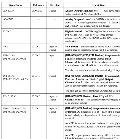
Table 3-1 describes the signals found on the I/O connectors. Not all signals are available on all devices.
Table 3-1. I/O Connector Signals
Signal Name Reference Direction Description
AI GND — — Analog Input Ground—These terminals are the reference point for single-ended AI measurements in RSE mode and the bias current return point for differential measurements. All three ground references—AI GND, AO GND, and D GND—are connected on the device.
AI <0..31> Varies Input Analog Input Channels 0 to 31—For single-ended measurements, each signal is an analog input voltage channel. In RSE mode, AI GND is the reference for these signals. In NRSE mode, the reference for each AI <0..31> signal is AI SENSE.
For differential measurements, AI 0 and AI 8 are the positive and negative inputs of differential analog input channel 0. Similarly, the following signal pairs also form differential input channels:
<AI 1, AI 9>, <AI 2, AI 10>, <AI 3, AI 11>, <AI 4, AI 12>, <AI 5, AI 13>, <AI 6, AI 14>, <AI 7, AI 15>, <AI 16, AI 24>, <AI 17, AI 25>, <AI 18, AI 26>, <AI 19, AI 27>,
<AI 20, AI 28>, <AI 21, AI 29>, <AI 22, AI 30>, <AI 23, AI 31>
AO <0..1> AO GND Output Analog Output Channels 0 to 1—These terminals supply the voltage output of AO channels 0 to 1.
AO GND — — Analog Output Ground—AO GND is the reference for AO <0..1>. All three ground references—AI GND, AO GND, and D GND—are connected on the device.
D GND — — Digital Ground—D GND supplies the reference for PFI <0..15>/P0/P1 and +5 V. All three ground
references—AI GND, AO GND, and D GND—are connected on the device.
+5 V D GND Input or Output
+5 V Power—These terminals provide a +5 V power source or can be used to externally power the digital outputs.
PFI <0..3>, PFI <8..11>/P0.<0..7>
D GND Input (USB-6210/6211/6215/6218 Devices)Programmable Function Interface or Static Digital Input
Channels 0 to 7—Each PFI terminal can be used to supply an external source for AI, AO, or counter/timer inputs.
You also can use these terminals as static digital input lines. PFI <4..7>,
PFI <12..15>/P1.<0..7>
D GND Output (USB-6210/6211/6215/6218 Devices)Programmable Function Interface or Static Digital Output
Channels 0 to 7—You can route many different internal AI, AO, or counter/timer outputs to each PFI terminal.
You also can use these terminals as static digital output lines. P0.<0..15>* D GND Input or
Output
(USB-6212/6216 Devices)Port 0 Digital I/O
Channels 0 to 15—You can individually configure each signal as an input or output.
PFI <0..7>/P1.<0..7>, PFI <8..15>/P2.<0..7>
D GND Input or Output
(USB-6212/6216 Devices)Programmable Function Interface or Digital I/O Channels 0 to 15—Each of these terminals can be individually configured as a PFI terminal or a digital I/O terminal.
As a PFI input, each terminal can be used to supply an external source for AI, AO, DI, and DO timing signals or counter/timer inputs.
As a PFI output, you can route many different internal AI, AO, DI, or DO timing signals to each PFI terminal. You also can route the counter/timer outputs to each PFI terminal. As a Port 1 or Port 2 digital I/O signal, you can individually configure each signal as an input or output.
Table 3-1. I/O Connector Signals (Continued)
+5 V Power
The +5 V terminals on the I/O connector can be use as either an output or an input. Both terminals are internally connected on the USB-621x.
+5 V Power as an Output
Because the USB-621x devices are bus powered, there is a 50 mA limit on the total current that can be drawn from the +5 V terminals and the digital outputs. The USB-621x monitors the total current and drops the voltage on all of the digital outputs and the +5 V terminals if the 50 mA limit is exceeded.
+5 V Power as an Input
If you have high current loads for the digital outputs to drive, you can exceed the 50 mA internal limit by connecting an external +5 V power source to the +5 V terminals. These terminals are protected against
undervoltage and overvoltage, and they have a fuse to protect them from short circuit conditions1. If your USB-621x device has more than one +5 V
terminal, you can connect the external power supply to one terminal and
use the other as a power source.
USER — — (USB-621x BNC Devices)User-Defined Channel—The USER
BNC connector allows you to use a BNC connector for a digital or timing I/O signal of your choice. The USER BNC connector is internally routed to the USER screw terminal. Refer to the appropriate USER section for your USB-621x BNC device in Appendix A, Device-Specific Information, for more information about the USER signal.
NC — — No connect—Do not connect signals to these terminals.
* USB-6212/6216 BNC/Mass Termination devices have eight digital I/O lines, P0.<0..7>.
1 USB-621x Screw Terminal/BNC devices have a 350 mA self-resetting fuse. USB-621x Mass Termination devices have a
750 mA user-replaceable socketed fuse. Refer to the USB Device Fuse Replacement section for information about replacing socketed fuses.
Table 3-1. I/O Connector Signals (Continued)
USB Chassis Ground
(USB-621x BNC Devices) For EMC compliance, the chassis of the USB-621x
BNC device must be connected to earth ground through the chassis ground.
The wire should be AWG 16 or larger solid copper wire with a maximum
length of 1.5 m (5 ft). Attach the wire to the earth ground of the facility’s power system. For more information about earth ground connections, refer
to the KnowledgeBase document, Earth Grounding for Test and
Measurement Devices, by going to ni.com/info and entering the info
code earthground.
You can attach a wire to the ground lug screw of any USB-621x BNC device, as shown in Figure 3-1.
Figure 3-1. Grounding a USB-621x BNC Device through the Ground Lug Screw
USB Device Fuse Replacement
(USB-621x Mass Termination Devices) USB-621x Mass Termination devices have a replaceable 0.75A,125V fuse (Littelfuse part number 0453.750) that protects the device from overcurrent through the +5 V terminal(s).
To replace a broken fuse in the USB-621x Mass Termination, complete the following steps while referring to Figure 3-2.
1. Remove the USB cable and any I/O signal wires from the device.
3. Replace the broken fuse in the socket. Figure 3-2 shows the fuse location.
Figure 3-2. USB-621x Mass Termination Fuse Location
4. Replace the device top and reattach with the screws.
Note Unscrewing and reinstalling the thread-forming screws over time will produce a
compromised connection between the device top and bottom.
1 0.75A,125V Fuse, Socketed
1
NA TIONAL INSTRUMENTS
NI USB-6216 16 Inp u
t
s , 16-b it, 400 k S
/
s
,
I
PWR/ACT LED Indicator
The PWR/ACT LED indicator indicates device status. Table 3-2 shows the
behavior of the PWR/ACT LED.
Table 3-2. PWR/ACT LED Status
LED State Device Status
Not lit Device not powered or device error. Refer to ni.com/support if
device is powered.
On, not blinking Device error. Refer to ni.com/support.
Single-blink Operating normally. Connected to USB Hi-Speed port. Refer to the
NI USB-621x Specifications for more information.
Double-blink Connected to USB Full-Speed port. Device performance might be
4
Analog Input
Figure 4-1 shows the analog input circuitry of USB-621x devices.
Figure 4-1. USB-621x Analog Input Circuitry
The main blocks featured in the USB-621x analog input circuitry are as follows:
• I/O Connector—You can connect analog input signals to the USB-621x device through the I/O connector. The proper way to connect analog input signals depends on the analog input ground-reference settings, described in the Analog Input Ground-Reference Settings section. Also refer to Appendix A,
Device-Specific Information, for device I/O connector pinouts.
• Mux—Each USB-621x device has one analog-to-digital converter
(ADC). The multiplexers (mux) route one AI channel at a time to the
ADC through the NI-PGIA.
• AI Ground-Reference Settings—The analog input ground-reference settings circuitry selects between differential (DIFF), referenced
single-ended (RSE), and non-referenced single-ended (NRSE) input
modes. Each AI channel can use a different mode.
DIFF, RSE, or NRSE
I/O Connector
AI <0..n> Mux
AI SENSE
AI GND
NI-PGIA
AI Ground-Reference
Settings
Input Range
Selection
ADC AI FIFO Digital AI Data
Isolators
Isolation Barrier (USB-6215/
• NI-PGIA—The NI programmable gain instrumentation amplifier (NI-PGIA) is a measurement and instrument class amplifier that minimizes settling times for all input ranges. The NI-PGIA can amplify or attenuate an AI signal to ensure that youuse the maximum resolution of the ADC.
USB-621x devices use the NI-PGIA to deliver high accuracy even when sampling multiple channels with small input ranges at fast rates.
USB-621x devices can sample channels in any order at the maximum
conversion rate, and you can individually program each channel in a sample with a different input range.
• ADC—The analog-to-digital converter (ADC) digitizes the AI signal
by converting the analog voltage into a digital number.
• AI FIFO—USB-621x devices can perform both single and multiple A/D conversions of a fixed or infinite number of samples. A large first-in-first-out (FIFO) buffer holds data during AI acquisitions to ensure that no data is lost. USB-621x devices can handle multiple A/D
conversion operations with DMA, interrupts, or programmed I/O.
• Isolation Barrier and Digital Isolators—Refer to Chapter 9,
Isolation and Digital Isolators on USB-6215/6216/6218 Devices, for more information.
Analog Input Range
The input range affects the resolution of the USB-621x device for an
AI channel. For example, a 16-bit ADC converts analog inputs into one
of 65,536 (= 216) codes—that is, one of 65,536 possible digital values.
So, for an input range of –10 V to 10 V, the voltage of each code of a 16-bit ADC is:
USB-621x devices use a calibration method that requires some codes (typically about 5% of the codes) to lie outside of the specified range. This calibration method improves absolute accuracy, but it increases the nominal resolution of input ranges by about 5% over what the formula shown above would indicate.
Choose an input range that matches the expected input range of your signal. A large input range can accommodate a large signal variation, but reduces the voltage resolution. Choosing a smaller input range improves the voltage resolution, but may result in the input signal going out of range.
10 V–(–10 V)
( )
216
For more information about setting ranges, refer to the NI-DAQmx Help or the LabVIEW Help in version 8.0 or later.
The following table shows the input ranges and resolutions supported by USB-621x devices.
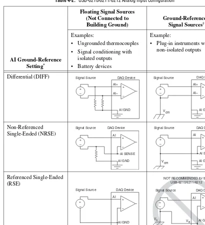
Analog Input Ground-Reference Settings
USB-621x devices support the following analog input ground-reference settings:
• Differential Mode—In DIFF mode, USB-621x devices measure the difference in voltage between two AI signals.
• Referenced Single-Ended Mode—In RSE mode, USB-621x devices measure the voltage of an AI signal relative to AI GND.
• Non-Referenced Single-Ended Mode—In NRSE mode, USB-621x
devices measure the voltage of an AI signal relative to the AI SENSE input.
The AI ground-reference setting determines how you should connect your AI signals to the USB-621x device. For more information, refer to one of the following sections depending on your device:
• Connecting Analog Input Signals on USB-6210/6211/6212 Devices
• Connecting Analog Input Signals on USB-6215/6216/6218 Devices
Ground-reference settings are programmed on a per-channel basis.
For example, you might configure the device to scan 12 channels—four differentially-configured channels and eight single-ended channels.
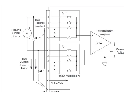
USB-621x devices implement the different analog input ground-reference settings by routing different signals to the NI-PGIA. The NI-PGIA is a differential amplifier. That is, the NI-PGIA amplifies (or attenuates) the difference in voltage between its two inputs. The NI-PGIA drives the ADC
Input Range
Nominal Resolution Assuming 5% Over Range
–10 V to 10 V 320 μV
–5 V to 5 V 160 μV
–1 V to 1 V 32 μV
with this amplified voltage. The amount of amplification (the gain) is determined by the analog input range, as shown in Figure 4-2.
Figure 4-2. NI-PGIA
Table 4-1 shows how signals are routed to the NI-PGIA.
For differential measurements, AI 0 and AI 8 are the positive and negative inputs of differential analog input channel 0. For a complete list of signal pairs that form differential input channels, refer to the I/O Connector Signal Descriptions section of Chapter 3, Connector and LED Information. AI ground-reference setting is sometimes referred to as AI terminal configuration.
Caution The maximum input voltages rating of AI signals with respect to AI GND (and for differential signals with respect to each other) are listed in the NI USB-621x Specifications. Exceeding the maximum input voltage of AI signals distorts the
measurement results. Exceeding the maximum input voltage rating also can damage the device and the computer. NI is not liable for any damage resulting from such signal connections.
Table 4-1. Signals Routed to the NI-PGIA
AI Ground-Reference Settings
Signals Routed to the Positive Input of the NI-PGIA (Vin+)
Signals Routed to the Negative Input of the NI-PGIA (Vin–)
RSE AI <0..31> AI GND
NRSE AI <0..31> AI SENSE
DIFF AI <0..7> AI <8..15>
AI <16..23> AI <24..31>
Vin+
Vm = [Vin+ – Vin–] × Gain Vm Vin–
PGIA +
–
Measured Voltage Instrumentation
Configuring AI Ground-Reference Settings in Software
You can program channels on an USB-621x device to acquire with different ground references.
To enable multimode scanning in LabVIEW, use NI-DAQmx Create
Virtual Channel.vi of the NI-DAQmx API. You must use a new VI for each channel or group of channels configured in a different input mode. In Figure 4-3, channel 0 is configured in differential mode, and channel 1 is configured in referenced single-ended mode.
Figure 4-3. Enabling Multimode Scanning in LabVIEW
To configure the input mode of your voltage measurement using the DAQ Assistant, use the Terminal Configuration drop-down list. Refer to the
DAQ Assistant Help for more information about the DAQ Assistant.
To configure the input mode of your voltage measurement using the
NI-DAQmx C API, set the terminalConfig property. Refer to the
NI-DAQmx C Reference Help for more information.
Multichannel Scanning Considerations
USB-621x devices can scan multiple channels at high rates and digitize the signals accurately. However, you should consider several issues when designing your measurement system to ensure the high accuracy of your measurements.
In multichannel scanning applications, accuracy is affected by settling
time. When your USB-621x device switches from one AI channel to
another AI channel, the device configures the NI-PGIA with the input range of the new channel. The NI-PGIA then amplifies the input signal with the gain for the new input range. Settling time refers to the time it takes the NI-PGIA to amplify the input signal to the desired accuracy before it is
sampled by the ADC. The NI USB-621x Specifications lists settling time.
of your measurements. To ensure fast settling times, you should do the following (in order of importance):
• Use Low Impedance Sources—To ensure fast settling times, your signal sources should have an impedance of <1 kΩ. Large source impedances increase the settling time of the NI-PGIA, and so decrease the accuracy at fast scanning rates.
Settling times increase when scanning high-impedance signals due to
a phenomenon called charge injection. Multiplexers contain switches,
usually made of switched capacitors. When one of the channels, for example channel 0, is selected in a multiplexer, those capacitors accumulate charge. When the next channel, for example channel 1, is selected, the accumulated charge leaks backward through channel 1. If the output impedance of the source connected to channel 1 is high enough, the resulting reading of channel 1 can be partially affected by the voltage on channel 0. This effect is referred to as ghosting.
If your source impedance is high, you can decrease the scan rate to allow the NI-PGIA more time to settle. Another option is to use a voltage follower circuit external to your DAQ device to decrease the impedance seen by the DAQ device. Refer to the KnowledgeBase
document, Decreasing the Source Impedance of an Analog Input
Signal, by going to ni.com/info and entering the info code rdbbis.
• Use Short High-Quality Cabling—Using short high-quality cables can minimize several effects that degrade accuracy including crosstalk, transmission line effects, and noise. The capacitance of the cable also can increase the settling time.
National Instruments recommends using individually shielded, twisted-pair wires that are 2 m or less to connect AI signals to
the device. Refer to the Connecting Analog Input Signals on
USB-6210/6211/6212 Devices or Connecting Analog Input Signals on USB-6215/6216/6218 Devices section for more information.
• Carefully Choose the Channel Scanning Order
– Avoid Switching from a Large to a Small Input
Range—Switching from a channel with a large input range to a
channel with a small input range can greatly increase the settling time.
Suppose a 4 V signal is connected to channel 0 and a 1 mV signal is connected to channel 1. The input range for channel 0 is –10 V
to 10 V and the input range of channel 1 is –200 mV to 200 mV.
When the multiplexer switches from channel 0 to channel 1,
the input to the NI-PGIA switches from 4 V to 1 mV. The
full-scale range. For a 16-bit device to settle within 0.0015% (15 ppm or 1 LSB) of the ±200 mV full-scale range on channel 1, the input circuitry must settle to within 0.000031% (0.31 ppm or 1/50 LSB) of the ±10 V range. Some devices can take many microseconds for the circuitry to settle this much.
To avoid this effect, you should arrange your channel scanning order so that transitions from large to small input ranges are infrequent.
In general, you do not need this extra settling time when the NI-PGIA is switching from a small input range to a larger input range.
– Insert Grounded Channel between Signal Channels—Another
technique to improve settling time is to connect an input channel to ground. Then insert this channel in the scan list between two of your signal channels. The input range of the grounded channel should match the input range of the signal after the grounded channel in the scan list.
Consider again the example above where a 4 V signal is connected to channel 0 and a 1 mV signal is connected to channel 1. Suppose the input range for channel 0 is –10 V to 10 V and the input range of channel 1 is –200 mV to 200 mV.
You can connect channel 2 to AI GND (or you can use the internal ground signal; refer to Internal Channels in the NI-DAQmx Help).
Set the input range of channel 2 to –200 mV to 200 mV to match
channel 1. Then scan channels in the order: 0, 2, 1.
Inserting a grounded channel between signal channels improves
settling time because the NI-PGIA adjusts to the new input range setting faster when the input is grounded.
– Minimize Voltage Step between Adjacent Channels—When
scanning between channels that have the same input range, the settling time increases with the voltage step between the channels. If you know the expected input range of your signals, you can group signals with similar expected ranges together in your scan list.
• Avoid Scanning Faster Than Necessary—Designing your system to scan at slower speeds gives the NI-PGIA more time to settle to a more accurate level. Consider the following examples:
– Example 1—Averaging many AI samples can increase the
accuracy of the reading by decreasing noise effects. In general, the more points you average, the more accurate the final result. However, you may choose to decrease the number of points you
average and slow down the scanning rate.
Suppose you want to sample 10 channels over a period of 20 ms and average the results. You could acquire 250 points from each channel at a scan rate of 125 kS/s. Another method would be to acquire 500 points from each channel at a scan rate of 250 kS/s. Both methods take the same amount of time. Doubling the number of samples averaged (from 250 to 500) decreases the effect of noise by a factor of 1.4 (the square root of 2). However, doubling the number of samples (in this example) decreases the time the NI-PGIA has to settle from 8μs to 4μs. In some cases, the slower scan rate system returns more accurate results.
– Example 2—If the time relationship between channels is not
critical, you can sample from the same channel multiple times and scan less frequently. For example, suppose an application requires averaging 100 points from channel 0 and averaging 100 points from channel 1. You could alternate reading between
channels—that is, read one point from channel 0, then one point from channel 1, and so on. You also could read all 100 points from channel 0 then read 100 points from channel 1. The second method switches between channels much often and is affected less by settling time.
Analog Input Data Acquisition Methods
When performing analog input measurements, you either can perform software-timed or hardware-timed acquisitions:
• Software-Timed Acquisitions—With a software-timed acquisition, software controls the rate of the acquisition. Software sends a separate command to the hardware to initiate each ADC conversion. In
NI-DAQmx, software-timed acquisitions are referred to as having
• Hardware-Timed Acquisitions—With hardware-timed acquisitions, a digital hardware signal, AI Sample Clock, controls the rate of the acquisition. This signal can be generated internally on your device or provided externally.
Hardware-timed acquisitions have several advantages over
software-timed acquisitions:
– The time between samples can be much shorter.
– The timing between samples is deterministic.
– Hardware-timed acquisitions can use hardware triggering.
Hardware-timed operations are buffered. In a buffered acquisition, data is moved from the DAQ device’s onboard FIFO memory to a PC buffer using USB signal streams or programmed I/O before it is transferred to application memory. Buffered acquisitions typically allow for much faster transfer rates than non-buffered acquisitions because data is moved in large blocks, rather than one point at a time.
One property of buffered I/O operations is the sample mode. The sample mode can be either finite or continuous:
– Finite sample mode acquisition refers to the acquisition of a specific, predetermined number of data samples. After the specified number of samples has been read in, the acquisition stops. If youuse a reference trigger, you must use finite sample mode.
– Continuous acquisition refers to the acquisition of an unspecified number of samples. Instead of acquiring a set number of data samples and stopping, a continuous acquisition continues until you stop the operation. Continuous acquisition is also referred to as double-buffered or circular-buffered acquisition.
Analog Input Digital Triggering
Analog input supports three different triggering actions:
• Start trigger
• Reference trigger
• Pause trigger
Refer to the AI Start Trigger Signal, AI Reference Trigger Signal, and
AI Pause Trigger Signal sections for information about these triggers.
A digital trigger can initiate these actions. All USB-621x devices support digital triggering. USB-621x devices do not support analog triggering.
Field Wiring Considerations
Environmental noise can seriously affect the measurement accuracy of the device if you do not take proper care when running signal wires between
signal sources and the device. The following recommendations apply
mainly to AI signal routing to the device, although they also apply to signal routing in general.
Minimize noise pickup and maximize measurement accuracy by taking the following precautions:
• Use differential AI connections to reject common-mode noise.
• Use individually shielded, twisted-pair wires to connect AI signals to the device. With this type of wire, the signals attached to the positive and negative input channels are twisted together and then covered with a shield. You then connect this shield only at one point to the signal source ground. This kind of connection is required for signals traveling through areas with large magnetic fields or high electromagnetic interference.
Refer to the NI Developer Zone document, Field Wiring and Noise
Considerations for Analog Signals, for more information. To access this document, go to ni.com/info and enter the info code rdfwn3.
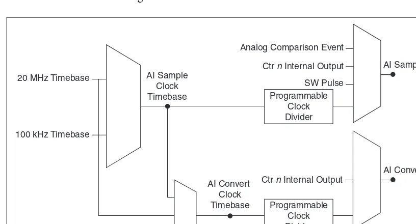
Analog Input Timing Signals
In order to provide all of the timing functionality described throughout this section, USB-621x devices have a flexible timing engine. Figure 4-4 summarizes all of the timing options provided by the analog input timing engine.
Figure 4-4. Analog Input Timing Options
USB-621x devices use AI Sample Clock (ai/SampleClock) and AI Convert
Clock (ai/ConvertClock) to perform interval sampling. As Figure 4-5
shows, AI Sample Clock controls the sample period, which is determined by the following equation:
1/Sample Period = Sample Rate 20 MHz Timebase
100 kHz Timebase
Programmable Clock Divider
Programmable Clock Divider AI Sample
Clock Timebase
AI Convert Clock Timebase
Analog Comparison Event
Ctr n Internal Output
SW Pulse
Ctr n Internal Output
Figure 4-5. Interval Sampling
AI Convert Clock controls the Convert Period, which is determined by the following equation:
1/Convert Period = Convert Rate
Note The sampling rate is the fastest you can acquire data on the device and still achieve accurate results. For example, if a USB-621x device has a sampling rate of 250 kS/s, this sampling rate is aggregate—one channel at 250 kS/s or two channels at 125 kS/s per channel illustrates the relationship.
Posttriggered data acquisition allows you to view only data that is acquired after a trigger event is received. A typical posttriggered DAQ sequence is shown in Figure 4-6. The sample counter is loaded with the specified number of posttrigger samples, in this example, five. The value decrements with each pulse on AI Sample Clock, until the value reaches zero and all desired samples have been acquired.
Figure 4-6. Posttriggered Data Acquisition Example
Channel 0
Channel 1
Convert Period
Sample Period
1
3 0
4 2 AI Start Trigger
AI Sample Clock
AI Convert Clock
Pretriggered data acquisition allows you to view data that is acquired before the trigger of interest, in addition to data acquired after the trigger. Figure 4-7 shows a typical pretriggered DAQ sequence. AI Start Trigger (ai/StartTrigger) can be either a hardware or software signal. If AI Start Trigger is set up to be a software start trigger, an output pulse appears on the AI Start Trigger line when the acquisition begins. When the AI Start Trigger pulse occurs, the sample counter is loaded with the number of pretriggered samples, in this example, four. The value decrements with each pulse on AI Sample Clock, until the value reaches zero. The sample counter is then loaded with the number of posttriggered samples, in this example, three.
Figure 4-7. Pretriggered Data Acquisition Example
If an AI Reference Trigger (ai/ReferenceTrigger) pulse occurs before the specified number of pretrigger samples are acquired, the trigger pulse is ignored. Otherwise, when the AI Reference Trigger pulse occurs, the sample counter value decrements until the specified number of posttrigger samples have been acquired.
USB-621x devices feature the following analog input timing signals:
• AI Sample Clock Signal
• AI Sample Clock Timebase Signal
• AI Convert Clock Signal
• AI Convert Clock Timebase Signal
• AI Hold Complete Event Signal
• AI Start Trigger Signal
• AI Reference Trigger Signal
• AI Pause Trigger Signal