University of Bergamo University of Padova
University of Trieste University of Udine University IUAV of Venezia
Ivan Giongo
ROLE OF TIMBER DIAPHRAGMS IN THE SEISMIC
RESPONSE OF UNREINFORCED MASONRY (URM)
BUILDINGS
Prof. Maurizio Piazza
Prof. Jason Ingham
UNIVERSITY OF TRENTO
Engineering of Civil and Mechanical Structural Systems
Ph. D. Head’s prof. Davide Bigoni
Final Examination 29 / 04 / 2013
Board of Examiners
Prof. Egidio Rizzi (University of Bergamo)
Dr. Dennis Kochmann (California Institute of Technology)
Prof. Spyros Karamanos (University of Thessaly)
ACKNOWLEDGEMENTS
I would like to gratefully thank my supervisors Maurizio Piazza and Jason Ingham for the support and trust that they have provided to me. I would like to express my sincere gratitude to Roberto Tomasi for his help and advice during these years.
I am also grateful to the members of the Timber Research Group of the University of Trento for their friendship: Ermanno Acler, Mauro Andreolli, Daniele Casagrande, Paolo Grossi, Cristiano Loss, Andrea Polastri, Simone Rossi and Tiziano Sartori.
I am thankful to the former undergraduate students Daniele Bertoldi, Lorenzo Dallavalle, Alfredo Rizzardi, Carlo Rodegher e Francesca Pintarelli for their precious help.
Many thanks are also extended to Dmytro Dhizur. Without his support it would not have been possible for me to conduct any experimental test at the “other side of the World”. Adolfo Preciado Quiroz and Kevin Walsh are thanked for their help with the diaphragm testing. Thanks are extended to Yuri Dhizur and Igor for their tireless assistance during almost all the Whanganui experience. New Zealand Natural Hazards Research Platform is gratefully acknowledged for providing funds for the diaphragm project.
Part of the research presented in this thesis has been carried out within the framework of the RELUIS Project which is financed by the Italian Emergency Management Agency.
SUMMARY
The research presented in this thesis was focused on timber floor diaphragms in unreinforced masonry (URM) buildings. The work was divided into two phases. The first phase was aimed at the investigation of the effects of the in-plane behavior of timber diaphragms on the global seismic response of URM buildings. The second phase was dedicated to the assessment and retrofit of timber floors, with particular attention to the out-of-plane behavior.
A study on the equivalent frame method, which is a more and more appreciated masonry modeling technique, is presented. Both as-built and strengthened timber floors were addressed. In order to understand the influence of the masonry modeling method on the seismic response of URM structures when flexible diaphragms are concerned, a simplified elastic no tension method was proposed. Such method is able to describe the characteristic nonlinear behavior of masonry (due to extremely low tensile strength) by means of a series of linear analyses based on a Rankine failure criterion.
An in-situ testing campaign on full-scale 100 year old timber diaphragms is presented. Both mechanical and dynamic in-plane properties of wood diaphragms were investigated. Cyclic and snap back tests were carried out thanks to an innovative ad hoc loading system, developed by means of wire ropes and steel pulleys. The loading system was designed to reproduce a realistic inertial load distribution and to be lightweight, versatile and easily relocatable from one diaphragm section to the next. The effect of different refurbishment techniques was also probed during the experimental campaign.
The outcomes of a testing campaign regarding out-of-plane refurbishment techniques of existing timber floors by means of timber to timber composite structures are described. A numerical model based on the theory of composite beams with incomplete interaction, was calibrated to take into account the real load distribution and connector spacing.
INDEX
Acknowledgements ... 3
Summary ... 5
Index ... 7
1 Introduction ... 11
1.1 Thesis Outline ... 13
1.2 References... 16
PART 1 ... 17
2 Pushover analysis of traditional masonry buildings: influence of refurbished timber-floors stiffness ... 19
2.1 Introduction ... 19
2.2 The modeling ... 20
2.2.1 The building ... 20
2.2.2 The wooden floors ... 23
2.3 The experimental data ... 23
2.4 Case study building ... 26
2.5 The analyses ... 27
2.5.1 The parametric analyses ... 27
2.5.2 Influence of diaphragms stiffness ... 33
2.6 Conclusions ... 37
3 Proposal of a simplified Elastic No Tension method for the seismic evaluation
of URM buildings with flexible diaphragms. ... 41
3.1 Introduction ... 41
3.2 Modeling of masonry ... 41
3.2.1 Method validation ... 45
3.2.2 Case study building ... 48
3.3 Modeling of wood diaphragm... 49
3.4 Analysis results ... 53
3.5 Conclusions ... 56
3.6 References... 57
4 Parametric analysis on timber diaphragm in-plane behavior ... 59
4.1 Introduction ... 59
4.2 Finite Element Model ... 59
4.2.1 Model validation ... 60
4.3 Parametric Analyses ... 62
4.4 Proposal of a formulation to determine the equivalent shear stiffness ... 73
4.4.1 Standard & Literature approaches ... 73
4.4.2 Analytical formulation ... 79
4.5 Conclusions ... 83
4.6 References... 85
5 Experimental campaign on the in-plane properties of timber diaphragms ... 87
5.1 Introduction ... 87
5.2 Campaign preparation ... 87
5.2.1 The Building ... 87
5.2.2 Floor sections... 88
5.2.4 The new anchoring system ... 90
5.3 Test setup ... 93
5.3.1 Loading system ... 93
5.3.2 Measuring devices ... 97
5.4 Mechanical properties of the materials ... 98
5.4.1 Metal components ... 98
5.4.2 Wood elements ... 99
5.5 Snap back tests ... 100
5.6 Cyclic tests ... 100
5.6.1 Specimen A ... 101
5.6.2 Specimen B ... 104
5.6.3 Specimen C ... 105
5.7 Data processing ... 109
5.7.1 Backbone curve Idealization ... 109
5.7.2 Determination of the equivalent stiffness ... 112
5.7.3 Period determination ... 115
5.7.4 Energy dissipation ... 121
5.7.5 Boundary condition assessment ... 123
5.8 Conclusions ... 125
5.9 References... 127
PART 2 ... 131
6 Experimental tests on timber-to-timber strengthening methods for improving the out-of-plane behavior of existing wood diaphragms ... 133
6.1 Introduction ... 133
6.2 Experimental data ... 133
6.4 Conclusions ... 147
6.5 References... 148
7 Proposal of a new method for cambering timber composite beams by means of sole screws ... 151
7.1 Introduction ... 151
7.2 The experimental tests ... 152
7.3 The numerical model ... 154
7.4 The analytical formula ... 157
7.5 Conclusions ... 167
7.6 References... 169
8 Experimental campaign on the compression pressure developed by screw fasteners ... 171
8.1 Introduction ... 171
8.2 Test setup ... 1711
8.3 Preliminary tests ... 1722
8.4 Main experimental campaign ... 1777
8.5 Test result comparison ...18080
8.6 Pressure prediction formula ... 1855
8.7 Conclusions ... 1877
8.8 References... 189
1
INTRODUCTION
Earthquakes have constantly highlighted in several parts of the World (e.g. Italy, Turkey, Greece, Portugal, New Zealand), that unreinforced masonry structures are a major source of life-loss and damage, particularly when timber diaphragms are present. Historic city centers of most Countries, are in fact comprised of URM buildings with timber diaphragms. Although each Country has its own peculiar typology of timber floors and different refurbishment techniques, it is possible to identify common behaviors and similar problems, especially when seismic hazard is concerned.
The seismic response of a masonry structure in fact is strictly related to the ability to behave as “box” with all its components which collaborate in resisting to the horizontal actions. Such behavior depends on the quality of the connections between the different structural elements and on the horizontal diaphragm in-plane stiffness. When the connection system between floor diaphragms and adjacent walls is deficient, the walls behave independently and local out-of-plane collapse mechanisms which involve overturning of the walls may be observed (Fig. 1.1).
Fig. 1.1 Out-of plane failure of masonry walls: a) L’Aquila Earthquake, Italy (2009) [Bursi et al. (2009)]; b) Christchurch Earthquake, New Zealand (2011) [Dizhur (2011)]; Emilia, Italy Earthquake
(2012) [www.adnkronos.com].
If the diaphragm-to-wall connections are adequate, then it is the in-plane stiffness that becomes the governing parameter in determining the global behavior of masonry buildings. By considering two limit cases, quite different seismic responses can be registered. In the presence of rigid diaphragms, the horizontal forces are distributed on
the resisting walls accordingly to the wall stiffness and to the wall position. In case of infinitely flexible diaphragms the horizontal force component that is transferred on a masonry pier, depends on the wall tributary area with respect to vertical loads. Therefore, it is a matter of basic importance to understand where the real condition falls.
The need to increase timber diaphragm stiffness and strength has generated, in the past times, strengthening solutions which recent earthquakes have demonstrated to be inadequate or, in some cases, even unfavorable. As a matter of fact, the substitution of timber floors with concrete ones and the insertion of a concrete curb “inside” the wall thickness, could yield significant self-weight increase and weakening of the existing masonry walls (Fig. 1.2).
Fig. 1.2 Umbria Marche Earthquake, Italy (1997): Collapse mode observed in masonry building reinforced by substituting existing timber floors with new concrete ones. [Borri, (2007)]
Therefore, after recent earthquakes, some floor refurbishment techniques have been reconsidered. Currently the Italian standard code on existing buildings, bans the possibility of inserting a concrete curb in the depth of the existing walls, and suggests alternative strengthening methods to be used for horizontal diaphragms. Among such methods, those which permits to improve both in-plane and out-of plane behaviors should be preferred.
aforementioned technique has some shortcomings concerning mainly the increase of dead load and the need for an additional structural depth over the existing decking. Moreover, it does not meet the requirement of “reversibility”, coming from the heritage administration agencies. Therefore, recently the interest in “dry”, “reversible” strengthening techniques (where the existing timber beams are coupled with thick timber planks, connected with different kinds of connection systems) has been aroused.
1.1 Thesis Outline
As mentioned in the summary, the research work has been organized into two parts. The first part pertains to the assessment of the timber diaphragm in-plane behavior and the analysis of the influence of flexible diaphragms on the global seismic response of traditional URM structures. In the second part of the thesis the out-of-plane behavior of wood floors is addressed, with keen attention to timber to timber refurbishment techniques.
PART 1
Pushover analysis of traditional masonry buildings: influence of refurbished timber-floors stiffness
The main purpose of Chapter 2 is to evaluate the effects that in-plane stiffness of different types of wooden diaphragms, yield on the capacity curve of a traditional masonry building, obtained by means of a nonlinear static (pushover) analysis. In order to determine it, an equivalent-frame modeling is employed to schematize a two-story building, the like of which is fairly common in the Italian building legacy. Both as-built and retrofitted wood floor types is taken into account. As to better understand and control all the aspects that rule the global seismic behavior of a masonry construction, a general-purpose finite element (FE) software is adopted. Therefore every "feature" is manually implemented.
Proposal of a simplified Elastic No Tension method for the seismic evaluation of URM buildings with flexible diaphragms
surface are eliminated, and the analysis is repeated with an updated geometry of the model. A “globally nonlinear” behavior is therefore depicted through a series of linear analyses. Another aspect that is analyzed, is whether timber diaphragm can be treated as “linear materials” when it comes to the global seismic analysis of a masonry building. Therefore a procedure to take into account wood diaphragm nonlinear behavior is proposed and validated on experimental data pertaining to both as-built and retrofitted timber floor typologies.
Parametric analyses on timber diaphragm in-plane behavior
A parametric study on single straight sheathed diaphragms is reported in Chapter 4. The structural analysis software SAP2000 [CSI 2004] is employed to develop a nonlinear model which is validated on experimental data from tests previously carried out at the University of Trento. Special attention is paid to the floorboard disposition and to the diaphragm deformed shape. To evaluate diaphragm deformations, an analytical formulation based on the revision of existing approaches is proposed and validated through the finite element model.
Experimental campaign on the in-plane properties of timber diaphragms
PART 2
Experimental tests on timber-to-timber strengthening methods for improving the out-of-plane behavior of existing wood diaphragms
In order to address the issue of improving the strength and the stiffness of timber floor diaphragms not only to face in-plane forces but also to bear out-of plane loads, an experimental campaign on timber-to-timber strengthening solutions, is presented in Chapter 6. The reinforcement elements consisted of thick timber planks which were arranged on top of the timber flooring and secured to the beam joists by using screw fasteners. Four different configurations of the connection system were tested. Experimental data are compared with theoretical values obtained through the theory of composite beams with incomplete interaction developed by [Newmark et al.] and through the approach suggested by [EN 1995]. A specific numerical model is realized in order to take into account both the real load distribution and the connectors spacing. Parametric analyses were performed in order to investigate the influence of these parameters on the global behavior. With regards to the Serviceability Limit State, particular attention was paid to the midspan deflection of the tested floors.
Proposal of a new method for cambering timber composite beams by means of sole screws
The possibility of cambering a timber beam by simply putting another beam on top of it and inserting screws inclined at 45° relative to the beam axis is investigated in Chapter 7. To this purpose, three experimental tests were performed at the Laboratory of the Department of Mechanical and Structural Engineering (DIMS) of the University of Trento and the results are reported. After the calibration of a numerical model to help in understanding the “cambering phenomenon”, an analytical formulation is proposed. The cambering procedure proved to be more effective when the fastener are inserted starting from the internal part of the beam, permitting to obtain significant values of upward deflection.
Experimental campaign on the compression pressure developed by screw fasteners
influence of different parameters such as screw size, screw angle, initial pressure, connector typology, wood density and time-dependence is studied.
1.2 References
ASCE-SEI 41/06, (2007) Seismic rehabilitation of existing buildings, American Society of Civil Engineers, Reston, Va.
Bursi O. S., Dusatti T., Pucinotti R., (2009) A Reconnaissance report. The April 6, 2009,
L’Aquila Earthquake. Italy
CSI [Computers and Structures Inc.], (2004), CSI Analysis Reference Manual For
SAP2000®, ETABS®, and SAFE®. CSI, Berkeley
Dhizur D., (2012) In-situ testing of Unreinforced Masonry Building in Whanganui, Research Symposium, University of Auckland, 12/11/2012
EN 1995-1-1, (2004), Eurocode 5: Design of timber structures - Part 1-1: General – Common rules and rules for buildings.
FEMA 356, (2000), Prestandard and Commentary for the Seismic Rehabilitation of
Buildings, American Society of Civil Engineers and Federal Emergency Management
Agency, Reston, VA
NZSEE, (2011), Assessment and Improvement of Unreinforced Masonry Buildings for
Earthquake Resistance, New Zealand Society for Earthquake Engineering, Wellington,
New Zealand
Newmark N.M., Siess C.P., Viest I.M., (1951), Tests and Analyses of Composite Beams
2
PUSHOVER ANALYSIS OF TRADITIONAL MASONRY
BUILDINGS: INFLUENCE OF REFURBISHED TIMBER-FLOORS
STIFFNESS
2.1 Introduction
2.2 The modeling
2.2.1 The building
The numerical model used to investigate the effects that the real in-plane stiffness of wooden floors yields on seismic behavior of masonry buildings, is based on the so-called "equivalent frame" method. Consequently every pier and every spandrel is schematized with an elastic frame element. The mechanical nonlinearities are concentrated in particular cross-sections (plastic hinges) placed both in the middle and in the ends of the elastic frames. Since the analysis of real “post-earthquake” masonry buildings has shown that most of the damages do not involve the intersections between piers and spandrels, rigid offsets are inserted where the vertical elements meet the horizontal ones. The length of these offsets depends on the geometry of the openings (windows and doors). In particular the effective height of a pier (correspondent to the elastic part of the frame) has been deduced from a formula developed by Dolce in 1989 [Dolce (1989)]. Referring to the in-plane behavior of walls, the bottom ends of the vertical frames (piers) have been modeled as fixed (FEMA 356). On the other hand, considering the global seismic performance of masonry buildings, the out-of plane stiffness of the walls has been regarded as negligible and therefore moment releases have been introduced at both ends of the piers (FEMA 356).
2.2.1.1 Piers
According to Magenes and Calvi [Magenes and Calvi (1997)], three different failure criteria have been considered: rocking, sliding and shear cracking. The following formulae have been used:
- Rocking:
⋅
=
−
⋅
u
u
P D
p
M
k f
1
2
(Eq. 2.1)where Mu = moment of resistance, P = axial load (concentrated), D = pier length, p =
P/Dt, t = pier thickness, fu = compressive strength of masonry, k = parameter depending
on the stress distribution assumed at the pier base (k = 0.85).(Eq. 2.1), is the same proposed in the Italian Code NTC 2008.
(
µ
)
α
=
+
+
vc
V
Dt
, c
p /
d
1 5
1 3
p
(Eq. 2.2)where Vd = "the ultimate load of a wall" [Magenes and Calvi (1997)], c,µ = mechanical
parameters related to the Mohr-Coulomb criterion, αv = M/VD (shear ratio), M,V =
moment and shear forces acting on the pier.
- Shear cracking:
+
⋅ ⋅
=
tu tu u p ff
D t
V
b
1 (Eq. 2.3)where Vu = Vd, ftu = tensile strength of masonry, b = coefficient depending on the shear
distribution at the central cross-section of the pier (b = 1 for uniform shear distribution, b = 1.5 for parabolic distribution). The tensile strength ftu is assumed to be equal to 1.5
times the mean shear strength of masonry fmv0 (under zero compressive stress).
(Eq. 2.3) is consistent with the formula suggested by the former Italian code O.P.C.M. 3431 for existing buildings.
In accordance with the suggestions contained in D.M. 14-01-2008 an elastic-perfectly plastic law has been assumed for both flexural and shear behavior. The post-elastic state has been modeled by means of rigid-perfectly plastic hinges [Pasticier et al. (2007)]. A "rocking hinge" has been inserted at each end of the elastic part of the frames (their activation occur when moments acting on these extremities reach Mu), with no
mid-span of the frames (as the external loads have been applied to the nodes of the frame, the shear diagrams are uniform). The hinge is activated by the minimum value between
Vd,top, Vd bottom, and Vu (Vd,top/ Vd bottom corresponds to Vd with αv calculated at the
top/bottom section of the elastic part of the pier). According to the Italian Code, the shear plastic phase has been limited to a maximum drift of 0.4% of the pier-height.
The values of p and αv, maintained constant during the analyses, have been deducted
from a linear static procedure.
2.2.1.2 Spandrels
Two "rocking hinges" without any limits to deformation have been added to the elastic ends of the spandrels. The ultimate moment Mu that activates the hinges, has been
determined as suggested in NTC 2008:
(
)
=
−
u p p
h
M
H
1
H /
0 85
,
ht
2
(Eq. 2.4)where Hp = 0.4fhmht, fhm = mean compressive strength of masonry in the horizontal
direction, h = height of the spandrel, t = thickness of the spandrel. Like for the piers, a "shear hinge" has been inserted at the center of the frames schematizing the spandrels. This hinge (indefinitely plastic) is activated when the shear force reaches the minimum value between the following two criteria:
=
up
M
V
l
2
(Eq. 2.5)
= ⋅ ⋅
t vm
V
h t f
0 (Eq. 2.6)where fmv0 = the mean shear strength of masonry (under zero compressive stress), l =
length of the spandrel.
2.2.1.3 Reinforced Concrete Stringcourses
beams. The failure criterion has been deducted from European Standard: Eurocode 2 [UNI EN 1992-1-1].
2.2.2 The wooden floors
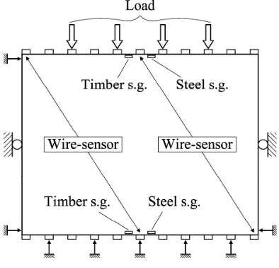
In order to study the influence that the in-plane stiffness of wood diaphragms has on the global behavior of a masonry building under seismic condition, different types of unreinforced/reinforced floors have been modeled. The mechanical properties of floors have been derived from an experimental campaign previously carried out at the Laboratory of the Department of Mechanical and Structural Engineering (DIMS) of the University of Trento [Piazza et al. (2008), Baldessari et al. (2009)]. Only the membrane behavior of floors has been taken into account, by means of nonlinear, two-dimensional finite elements. Considering the test set-up (Fig. 2.3), an equivalent shear stiffness Geq
has been calculated from the experimental data, regarding the diaphragm deformation as equal to the shear deformation of a simply supported beam under a uniform load distribution.
χ
⋅∆ ⋅
=
⋅ ⋅ ⋅∆
eq
W L
G
B t
f
8
(Eq. 2.7)where χ = the shear factor = 1, L = floor span perpendicular to the load direction, B = floor span parallel to the load direction, t = floor (membrane) thickness, ∆W = lateral
load applied [N], ∆f = mid span deflection.
2.3 The experimental data
Fig. 2.1 Different timber-floor in-plane-shear strengthening techniques: (a) existing simple layer of wood planks on the timber beams; (b) second layer of wood planks crossly arranged to the existing one and fixed by means of steel studs; (c) diagonal bracing of the existing wood planks by
means of light steel plates or FRP laminae; (d) three layers of plywood panels glued on the existing wood planks; (e) a stud−connected reinforced concrete slab (all measures in mm)
Fig. 2.3 The test apparatus
2.4 Case study building
The masonry building selected for the parametric analyses has been found in the literature [Righetti and Bari (1993)]. The choice has been prompted by the need of analyzing a masonry construction neither extremely irregular (the results would have been too dependent on the specific structure studied), nor particularly regular (as not to be too dissimilar from "real buildings"). Furthermore, since the structure is a two-story building, it is possible not to consider the variation in axial forces that the development of the pushover analysis yields; as suggested by the Italian Code in its former version [OPCM 3431].
Fig. 2.5 Analyzed building
Weight density of masonry γm 18 kN/m
3 Characteristic compressive strength of a brick fbk 10 MPa Characteristic compressive strength of masonry fk 4.5 MPa Characteristic shear strength of masonry (under zero compressive stress) fvk0 0.2 MPa
Elastic modulus of masonry E 4500 MPa
Shear modulus of masonry G 1800 MPa
Friction parameter µ 0.4
Tab. 2.1 Mechanical properties of masonry
Weight density of concrete γc 24 kN/m3 Characteristic compressive strength of concrete Rck 30 MPa Elastic modulus of concrete E 30 GPa
Tab. 2.2 Mechanical properties of concrete
2.5 The analyses
2.5.1 The parametric analyses
Together with the in-plane stiffness of wooden floors, many other parameters that affect the global seismic behavior of a traditional building, have been analyzed. As to evaluate the influence of spatial variability of the seismic ground motions, the mass center has been moved into different positions (∆x = ±0.54 m, ∆y = ±0.66 m) as counseled by the Italian Code. No differences have been observed in the static pushover curves related to different positions of the mass center (hypothesis of rigid diaphragm).
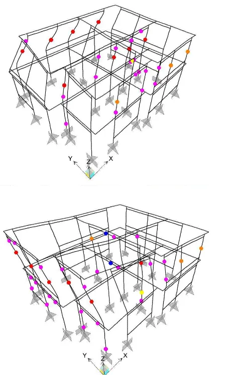
Two different lateral load patterns have also been applied during the pushover analyses: an inverted triangle (first mode) load pattern and a mass proportional one. While in the y direction the two patterns have produced no effects on the capacity curve, in the x direction the maximum base shear shows a difference greater than 30%. As one can see from Fig. 2.6, the mass proportional pattern stresses the first story more than the other (there are more active hinges), delaying the formation of plastic hinges in the upper story. This, considering that the global failure (x direction) is always a second-story mechanism, generates an increase in resistant base shear. It would appear that the following sentence contained in the ASCE Standard [ASCE/SEI 41-06]: "Recent
Fig. 2.6 X direction deformed shape - (Inverted triangular load pattern on the left; mass proportional load pattern on the right) - Plastic hinges: purple = rocking hinge, red = hinge that has
reached the deformation limit, yellow = bottom shear hinge, orange = top shear hinge
In order to determine the effects that the stiffness of the stringcourses induces on the seismic performance of an existing building, the elastic modulus of concrete has been varied, from the one of un-cracked material (30 GPa) to zero (the MOE used in all the other models has been 15 GPa, corresponding to the cracked material). Neither the base shear, nor the control point displacement have shown appreciable sensitivity to stringcourses stiffness. Only a predictable reduction in "global elastic stiffness" has been observed as the MOE value has decreased (Fig. 2.7).
spandrels in the elastic phase. On the other hand (as expected) if one neglects stringcourses stiffness, "rocking hinges" are activated at the ends of some spandrels. On the contrary, regarding stringcourses as un-cracked, yields the activation of plastic hinges in the stringcourses themselves.
Fig. 2.7 Global secant elastic stiffness vs. concrete MOE
Fig. 2.8 Cantilever beams model (soft spandrel hypothesis)
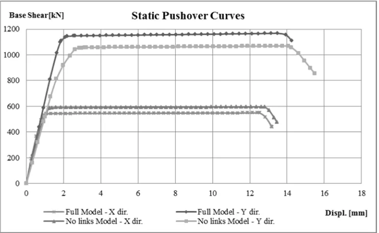
Another aspect subjected to investigation has been the possible birth of fictitious internal forces, owing to the rigid links that connect orthogonal systems of walls. So as to seek the effects of these links, a model of the building with none of them has been created (rigid diaphragm hypothesis, Fig. 2.11). From the results (Fig. 2.12) it is possible to see that in y direction the removal of the links, reduces both the global elastic stiffness and the maximum base shear. As one might expect, it would appear that those reductions are due to a less restrained building. Nonetheless, in x direction, an increase in total shear resistance has been observed. A reason may be that if one eliminates the coupling action generated by the links, then the bending stresses at the top of the piers grow (under the same level of lateral loads); this leads to an extension of the effective length of compression, strictly related to a variation of αv, that makes the shear
resistance (Vd,top) raise. Since the global failure mechanism, in x direction, is associated
with the formation of shear hinges at the top of the second-story piers, an increase in maximum base shear should therefore be considered plausible.
Fig. 2.11 Model without any link between perpendicular systems of walls
2.5.2 Influence of diaphragms stiffness
In Fig. 2.13 and Fig. 2.14 the results of static pushover analyses with the different wooden floors are reported. It is quite evident that, in terms of displacement capacity, the most common as-built traditional floor (single straight-sheathing) embodies a poor solution for a masonry building placed in a seismic zone (even though the tested one was very well-made, far beyond the common standard). Furthermore one can see that modeling single straight-sheathed floors with rigid diaphragms leads to overestimate both the shear resistance and the ultimate displacement of approximately 20% and 100% respectively. The reason is that rigid floors are capable of involving in the failure mechanism almost all the walls (story mechanism). Actually when the building reaches the collapse point (80% of the shear resistance) nearly all the piers, directed along the earthquake direction, have already gone beyond the plastic threshold (Fig. 2.16). On the other hand, quite a low in-plane stiffness means that there is little "collaboration" between the systems of walls. That is to say, the failure occurs when a single system of walls attains its ultimate displacement (Fig. 2.15). As a result, the analysis ends with many of the piers in the elastic phase, preventing the structure from obtaining the performance observed under the rigid diaphragms hypothesis.
Apart from the single straight-sheathed floor (whose in-plane stiffness is almost negligible), it appears that the maximum base shear is not affected by variation of the in-plane stiffness of diaphragms. In addition, in both directions the global stiffness does not show appreciable differences changing the type of floor refurbishment.
Fig. 2.13 Nonlinear static analyses: capacity curves
Fig. 2.15 Deformed shape (single straight-sheathing hyphothesis): x dir. on the top, y dir. on the bottom
2.6 Conclusions
From the presented results it would appear that a floor strengthening and stiffening is quite basic to the improvement of the seismic response of a masonry construction. Yet, the choice of the type of refurbishment does not seem to be of any relevance at all. Nonetheless, before leap to conclusion one should consider that the capacity curve is strictly linked to the building geometry and to the load distribution. Moreover, although the global behavior could be not affected by the in-plane floor stiffness, not so is the local one.
2.7 References
Baldessari, C., Piazza, M., Tomasi, R., (2009). The refurbishment of existing timber
floors: characterization of the in-plane behaviour. ISBN: 978-0-415-55804-4. Protection
of Historical Buildings. PROHITECH 09, London: Taylor & Francis, 255-260.
Calderini, C., Cattari, S., Lagomarsino, S., (2009). In-plane strength of unreinforced
masonry piers. Earthquake Engineering and Structural Dynamics, 38(2), pp. 243-267.
Cattari, S., Curti, E., Galasco, A., Resemini, S. (2005). Analisi sismica lineare e
non lineare degli edifici in muratura: teoria ed esempi di applicazione secondo OPCM 3274/2003 e 3431/2005. – collana Edilizia-Progettare e costruire, Ed.
Esselibri-Simone, Naples. (in Italian).
Dolce, M., (1989). Schematizzazione e modellazione per azioni nel piano delle pareti,
Corso sul consolidamento degli edifici in muratura in zona sismica. Ordine degli
Ingegneri, Potenza. (in Italian)
Magenes, G., Calvi, G. M., (1997). In-plane seismic response of brick masonry walls. Earthquake Engineering and Structural Dynamics, 26, 1091-1112.
Magenes, G., Bolognini, D., Braggio, C. (2000) Metodi semplificati per l'analisi
sismica non lineare di edifici in muratura. CNR-Gruppo Nazionale per la Difesa dai
Terremoti. Rome. (in Italian).
Pasticier, L., Amadio, C., Fragiacomo, M., (2008). Non-linear seismic analysis and
vulnerability evaluation of a masonry building by means of the SAP2000 V.10 code.
Earthquake Engineering and Structural Dynamics, 39, 467-485.
Piazza, M., Baldessari, C., Tomasi, R., Acler, E. (2008). Behaviour of refurbished
timber floors characterized by different in-plane stiffness. Structural Analysis of
Historical Constructions, Bath, U.K., Dina D’Ayala, E. Fodde (Eds.).
Righetti, G., Bari, L. (1993). L'edificio in muratura. La muratura portante in laterizio
normale e porizzato: caratteristiche e prestazioni. Consorzio Poroton, Ed. Lambda,
Padua. (in Italian).
D.M. 14-01-2008. (2008). Norme Tecniche per le Costruzioni. NTC 2008. (in Italian).
FEMA 356. (2000). Prestandard and Commentary For the Seismic Rehabilitation of
Buildings. Federal Emergency Management Agency.
FEMA 440. (2005). Improvement of Nonlinear Static Seismic Analysis Procedures. Federal Emergency Management Agency.
NZSEE. (2006). Assessment and Improvement of the Structural Performance of
Buildings in Earthquakes. Recommendations of a NZSEE Study Group on
Earthquake Risk Buildings.
O.P.C.M. 3431. (2005). Ulteriori modifiche ed integrazioni all'O.P.C.M. 20 marzo 2003 n.
3274, recante «Primi elementi in materia di criteri generali per la classificazione sismica del territorio nazionale e di normative tecniche per le costruzioni in zona sismica». (in
Italian).
UNI EN 1996-1-1. (2006). Eurocode 6 : Design of Masonry Structures. Part 1-1 :
General Rules for Buildings—Rules for Unreinforced and Reinforced Masonry.
UNI EN 1992-1-1. (2005). Eurocode 2: Design of concrete structures Part 1-1: General
3
PROPOSAL OF A SIMPLIFIED ELASTIC NO TENSION METHOD
FOR THE SEISMIC EVALUATION OF URM BUILDINGS WITH
FLEXIBLE DIAPHRAGMS
3.1 Introduction
The main purpose of this chapter is to deepen the understanding of the effects of different modeling techniques when evaluating the seismic response of URM buildings with timber diaphragms. The results of the analyses reported in Chapter 2 showed that the capacity curves obtained by employing an equivalent frame method, are characterized by a clear plateau which is related to the assumptions behind the plastic hinges property definition. Another issue that is addressed in the present chapter, is to determine whether the wood diaphragms (both as built and refurbished ones) are to be treated as linear materials or not. Several studies have shown that timber floors, when subjected to significant lateral loads, exhibit a highly nonlinear behavior. Since a yielding point is not always clearly identifiable [Piazza et al. (2011)], one cannot easily fit the experimental data with a bilinear curve nor can define, a priori a target displacement in which determining an equivalent secant stiffness. As a matter of fact, the diaphragm requirements in terms of displacement are related to the masonry skeleton the floor is connected to. In order to sort all these issues out, a simplified elastic no-tension (ENT) method for modeling masonry structures was proposed.
3.2 Modeling of masonry
Elastic no tension models (ENT) represent a first step towards finer modeling approaches and could be considered a reasonable compromise between accuracy and feasibility.
Unfortunately ENT materials are highly sensitive to boundary conditions and prone to lack of solution and excessive displacements. One famous example of this, is described by [Como (2010)]. The author considers a panel (unit depth) loaded as in Fig. 3.1, with both ends free to deform. Applying the Hooke’s law it can be seen that the extremities of the uniform loaded portion of the panel, shorten of a quantity ∆a equal to:
∆ =
a=
pa L
p L
Ea
2
E
2
(Eq. 2.1)The right portion of the panel is subjected to compression (N = pb/2) and also bending (M = pb2/12) which makes its top section rotate anticlockwise. Thanks to the Navier’s
formula it can be demonstrated that the left fiber of this portion undergoes a displacement ∆b:
∆ =
b+
=
= ∆
apb L
L b
p L
M
Eb
Eb
3E
12
2 2
2
2
2
(Eq. 2.2)Along the line between the two portions, fractures inevitably develop. If b is sufficiently small, the maximum amplitude ∆’ of these openings can be determined relying on the beam theory:
∆ =
'
M L
=
pL
EJ
E b
2 2
1
8
8
(Eq. 2.3)When the zone which the triangular part of the load is applied to, gets smaller and smaller or in other words when b → 0, ∆’ becomes:
→
∆ = ∞
b
lim '
0
Fig. 3.1 Example of singularity in the displacement field of a ENT panel
Hence a simplified method was formulated in order to take into account a very limited tensile strength and avoid the typical problems related to ENT models. So as to achieve this, a “global” Rankine failure criterion (with no limits in compression, Fig.3.2) was adopted, maintaining though an infinite linear elastic behavior throughout all the various steps the analysis was comprised of. To make it clearer, let us consider a displacement controlled analysis on a simple masonry pier, modeled with planar linear elastic finite elements, as in Fig.3.3a. The pushover analysis has been divided into five steps (from A to E). After the first step a check on the principal stresses has to be made: if one of the principal stresses (σI, σII) of a generic element exceeds the masonry tensile strength,
then the element is eliminated and the external force needed to maintain the structure at a displacement equal to ∆A decreases (Fig.3.3b). Thanks to the linear elastic behavior of the material, it is possible to stop the analysis right after the first step, do the stress check, unload the structure, eliminate the elements that are outside the failure surface and then reload up to the ∆A displacement being confident to reach the A’ point. Repeating this procedure for every step and connecting the points A’,B’…E’ (Fig.3.3d,e), one obtains the capacity curve of the structure.
The method implementation was accomplished by means of SAP2000 and the CSI’s Open Application Programming Interface that guaranteed the complete automation of the procedure.
Fig.3.2 Failure criterion in terms of principal stresses (ft = tensile strength of masonry)
Fig.3.3 Simplified ENT procedure
Fig.3.4 Flow diagram
3.2.1 Method validation
In order to validate the proposed method a case study was selected from the literature. The choice fell on the “Catania Project” [Liberatore (2000)], an Italian research project involving several research groups, proposed by the National Group for Earthquake
Defence. In particular the attention was focused on the internal wall of the building sited
in Via Martoglio (Catania, Italy,Fig.3.5), whose mechanical parameters are reported in Table 1. According to the Italian Standards [C.M.617 (2009)], a value equal to 1.5 times
Structure’s modeling through 2D shell elements
Linear Analysis of the Model
∀
F.E. check if
MAX{
σ
11;σ
22}>f
tDeletion of the F.E. External load application
Increase of the horizontal load
STOP
NO
YES
YES
Base Shear
the shear strength, was assumed for the tensile strength of masonry (ft = 1.5τk = 0.24
MPa).
Fig.3.5 Via Martoglio wall – Unloaded condition (on the left), ultimate condition (on the right)
With the aim of applying a prescribed load distribution (e.g. mass proportional, first mode proportional) in a displacement controlled analysis, an equivalent isostatic loading system was adopted [Anthoine (2006)]. The horizontal forces were introduced into the model at the story level, in correspondence with the concrete curbs, together with the vertical loads (so as to avoid any mass loss when an element is deleted due to excessive traction). The meshing of the wall was performed through four-node (2x2 Gauss points), two-dimensional finite elements (with just membrane behavior) whose maximum size (0.2x0.2 m2) was determined after a sensitivity analysis. It should be noted that the mesh dependence is related to the analysis step dimension.
Weight density of masonry γm 17 kN/m3
Tensile strength of a brick fbt 1 MPa
Compressive strength of masonry fu 6.0 MPa
Shear strength of masonry τk 0.16 MPa
Elastic modulus of masonry E 1600 MPa
Shear modulus of masonry G 300 MPa
Cohesion c 0.15 MPa
Friction parameter µ 0.5
Elastic modulus of concrete curbs Ec 20000 MPa
From the study of the damage evolution it can be stated that the first cracks appeared on the lintel above the main door at the ground floor. Then, a progressive reduction of the coupling effect offered by the spandrels was observed (starting from the lower stories) and consequently the formation of rocking mechanisms at the base of the ground story piers. The shear resistance of the wall is given in Fig.3.6 (V = 1002 kN). With respect to the data reported in Table 2 (there is a significant scatter in the results of the different research groups) the shear resistance obtained through the proposed method is somewhat on the safe side. It should be underlined that the ultimate load is strictly related to the ft value. If ft = 2τk had been used, a shear resistance close to 1300
kN would have been obtained. As far as displacements are concerned, the proposed
method exhibited the collapse point at 1.96 cm, very close to when the research group of Pavia detected the formation of a soft-story (Fig.3.6). On the other hand, as expected, it was quite distant from the ultimate displacement shown by the POR based methods (L’Aquila research group) which do not consider any damages of the spandrels.
Model Research Units V (kN)
Elastic curbs E = 20000MPa
Basilicata Genova Pavia 2050 1492 1227
Elastic curbs E = 20000MPa (rigid offsets) Basilicata 2226
Elastic curbs E = 4000MPa
Basilicata Genova Pavia 2050 1263 848
POR, piers’ height = interstorey height
POR, piers’ height = openings’ height
L’Aquila
L’Aquila
1502
1630
POR90, piers’ height = interstorey height L’Aquila 1394
Tab. 3.2 Catania Project results
3.2.2 Case study building
Fig.3.7 Case study building (on the left and on the right) and the isostatic loading system (in the middle)
It is known that the choice of the control point has a great influence on the determination of the capacity curve. In addition, owing to the features of the loading system, it was not rare to observe a decrease (from a certain time onwards) in the displacement of the monitored point. Therefore it was chosen of monitoring the building displacement in correspondence with the frame element representing the actuator. Considering that this element is positioned at about two third of the building height, the resulting capacity curves are on the safe side in terms of ultimate displacement.
3.3 Modeling of wood diaphragm
u u i
F
F( )
F / k
δ
δ
δ
⋅
=
+
(Eq. 2.5)where δ is the midspan displacement, F(δ) is the force at the diaphragm’s end, ki is the
initial stiffness and Fu is the ultimate force. Fu is obtained multiplying the unit shear
strength of the diaphragm νu by its width [Paquette & Bruneau (2006)]. With reference to
every floor typology tested by Baldessari et al., all the parameters required for determining the backbone curves are given in Table 3.
νu [kN/m] Fu [kN] ki [kN/mm] Single Straight Sheathing 52.0 208.0 1.1
Double Sheathing 67.6 270.4 11.2
Steel Plates 59.8 234.4 23.2
FRP Laminae 51.8 207.2 45.1
Concrete Slab 85.4 341.6 60.0
Plywood Layers 64.8 259.2 106.1
Tab. 3.3 Parameters for ABK formula
Both the experimental tests and the parametric analyses performed on FEM models (Fig.3.9) showed that the deformed shape of the diaphragms are extremely close to that of a uniformly loaded shear beam. Consequently an equivalent shear stiffness Geq was
calculated regarding the diaphragm deformation as equal to the shear deformation of a simply supported beam under a uniform load distribution.
2 ( )
( )
8
eqF
L
G
B t
δ
δ
δ
⋅
=
⋅ ⋅ ⋅
(Eq. 2.6)external frame of rigid rods and two internal diagonal rods whose stiffness is equal to
Geq multiplied by the floor thickness, a mean value of shear strain ɣ* was calculated for
every δ (Fig.3.8). So as to take into account the nonlinear behaviour of the floors, the
following iterative procedure was developed. The analysis begins with the shear stiffness of the floors equal to G1 (Fig.3.8). At the end of the first step, the angular
deformation of each cell is calculated: if the maximum ɣ is equal or smaller than ɣ*1, it is
possible to proceed with the stress check and the element deletion, otherwise the stiffness has to be changed and the step rerun. This process must be repeated after each step.
Fig.3.8 Equivalent shear stiffness (Double sheathing)
Fig.3.10. Diaphragm modeling
3.4 Analysis results
Fig.3.11 presents the capacity curves of the case study building for the analyzed diaphragms. It can be seen that the in-plane stiffness of floors plays a negligible role in determining the global response of the structure (all the curves are practically the same). A probable reason can be found in the distance between the mass center and the center of stiffness which is smaller than 0.5 m. In order to increase the stress state of the diaphragms, the model was modified by halving the thickness of the north wall (moving therefore the center of stiffness). As a result, a very slight difference was registered, denoting an increase in the performance as the floor stiffness grew (Fig.3.12). It should be noted that in masonry buildings the bulk of the structure is represented by the walls. Consequently, the north-wall’s stiffness-variation generated by the halving of the thickness, was somehow counterbalanced by the reduction in horizontal force (acting on the north wall) due to the mass diminishing. Therefore it was decided to apply an additional eccentricity of 2 m to the mass center, even if that was not consistent with the building geometry. From Fig.3.13 it is possible to observe that the higher the floor stiffness, the greater the shear resistance and the ultimate displacement. This result seems not to be in good agreement with chapter 2 where, apart from the single straight sheathing, it appears not to be any significant variations in the pushover curves between the different floor typologies. The causes might be found in the different method adopted for modeling masonry (equivalent frame method) and in the building characteristics.
Fig.3.11 Capacity curves (different floor-typologies)
Fig.3.13 Capacity curves (2 m of additional eccentricity to the mass centre)
3.5 Conclusions
From the presented results it would appear that modeling the real in-plane stiffness of diaphragms becomes quite important only in presence of remarkable eccentricity between the mass center and the center of stiffness. However, it should be taken into account that in URM buildings, the seismic mass associated with floors is very small in comparison with the mass of the walls. Therefore the position of the center of mass is related to that one of the center of stiffness.
In addition, it seems that modeling wood diaphragms with a linear elastic in-plane behavior is sufficient to describe the global seismic response of URM buildings.
As far as the proposed simplified ENT method is concerned, it has shown to be quite easy to handle and able to follow the damage evolution. Since after each step of the analysis, a copy of the up-to-date model is automatically saved, it is possible to check the stress distribution step by step
3.6 References
Piazza M., Polastri A., Tomasi R., (2011), Ductility of timber joints under static and cyclic
loads. Proceedings of the Institution of Civil Engineers, Structures and Buildings, v. 164,
n. SB2 (2011), 79-90
Heyman J., (1995), The stone skeleton, Cambridge University Press
Liberatore D., (2000), Progetto Catania: Indagine sulla risposta sismica di due
edifici in muratura (Project Catania: Investigation on the seismic response of two masonry buildings), GNDT – National Group for Seismic Protection: Rome, (in
Italian)
Baldessari C., Piazza M., Tomasi R., (2009), The refurbishment of existing timber floors:
characterization of the in-plane behaviour, Protection of Historical Buildings
PROHITECH 09, LONDON: Taylor & Francis, 2009, 255-260
Agbabian & Associates, S.B. Barnes & Associates, and Kariotis & Associates, (1984),
(ABK) A Joint Venture; Methodology for mitigation of seismic hazards in existing unreinforced masonry buildings: The methodology. El Segundo, Calif.
Como M., (2010), Statica delle costruzioni storiche in muratura, Aracne editrice S.r.l.
C.M. 617: 02-02-2009, Istruzioni per l'applicazione delle «Nuove norme tecniche per le
costruzioni» di cui al decreto ministeriale 14 gennaio 2008. (In italian)
CSI [Computers and Structures Inc.], (2004), CSI Analysis Reference Manual For
SAP2000®, ETABS®, and SAFE®. CSI, Berkeley
Anthoine A., (2006), A simple displacement control technique for pushover analyses, Earthquake Engineering and Structural Dynamics 35, 851-866
Paquette J., Bruneau M., (2003), Pseudo-dynamic testing of unreinforced masonry
4
PARAMETRIC ANALYSIS ON TIMBER DIAPHRAGM IN-PLANE
BEHAVIOR
4.1 Introduction
In the previous chapters diaphragm modeling was based on experimental data which inevitably are affected by a certain degree of “particularism”. Therefore, in order to develop a general formulation which can be adopted for various diaphragm configurations, a thorough parametric analysis was conducted by means of a numeric model. The analysis was focused on single straight-sheathed diaphragms. A summary of the most significant results produced by such analysis is reported in the present chapter.
4.2 Finite Element Model
The numerical model employed for the parametric study on single straight sheathed wooden floors relies on relatively consolidated assumptions which are quite common in literature [Brignola et al. (2008), Peralta et al. (2003), Wilson (2012)]. The first one of which is that the timber elements (boards and joists) are considered as linear-elastic. As a result, all the nonlinearities are concentrated in the fastener (nail) behavior. Secondly, no material penetrations or contact issues are taken into account. Friction phenomena are also neglected. The Finite Element Model (FEM) was realized by means of SAP2000 [CSI (2004)], a quite widespread software for structural analysis and design. Timber joists and planks were modeled by linear elastic frame elements, while nails were represented by nonlinear (multi-linear elastic) link elements connected to the timber frame elements through rigid link elements. In case of an interrupted board, a “physical discontinuity” was introduced in the frame element representing the board (Fig. 4.1).
The nonlinear behavior assigned to the nails was derived from the curve proposed by McLain [McLain (1975)]:
(
δ
)
= ⋅
+
Where F’ is load applied to the nail, δ is the nail slip, A and B are experimentally derived parameters. Parameter A is a function of the specific gravity of the timber elements constituting the joint. Parameter B [Pellicane et al. (1991)] was determined in accordance with the procedure proposed by Wilkinson [Wilkinson )1971)] which relies on the research carried out by Kuenzi (1955) where the nail is regarded as a beam on elastic foundations. Since each degree of freedom (DoF) of the multi-linear element behaves independently, such nonlinear curve (Eq. 4.1) was assigned to the translational DoFs U2 and U3. The DoFs U1, R2 and R3 were fully restrained (no flexural or axial nail deformations were allowed) while R1 (torsional) was set free (Fig. 4.1).
Fig. 4.1 Numeric modeling details (two nail-couples for each joist)
4.2.1 Model validation
The numerical model was validated through the data obtained from the experimental campaign carried out at the University of Trento in 2007 (Laboratory of the Department of Mechanical and Structural Engineering) [Piazza et al. (2008), Baldessari et al. (2009)]. Two different sized specimen were available for the validation: 1 small scale (2.0 m x 1.0 m, Fig. 3) and 1 full scale (5.0 m x 4.0 m, Fig. 4.2). The steel chord present on the full scale floor was modeled through linear elastic frame elements connected to the joists and floorboards by means of rigid link elements (the stiffness of the torsional spring R1 was assumed equal to zero). Boundary conditions and loading pattern reproduced those adopted in the testing campaign by Baldessari et al.. Consequently,
Continuous board Interrupted boards
Linear elastic frame element
Nonlinear link element Rigid link element
U1
U2 U3
R3 R1
hinges were introduced at the mid length of the lateral joists (tests were carried out only in the direction parallel to the joists) and the external force was applied through a 1 point load (small scale specimen) and 4 point loads (full scale specimen). Fig. 4.3 shows the good agreement registered between the experimental curve and the pushover curve obtained from the numeric model.
Fig. 4.2 FEM validation (5.0 m x 4.0 m specimen)
Fig. 4.3 FEM validation (2.0 m x 1.0 m specimen)
0 5 10 15 20 25 30 35
0 20 40 60
T
o
ta
l
L
o
a
d
[
k
N
]
Midspan displacement [mm]
Experimental Curve Numeric Model hinge
hinge
[Baldessari et al.] testing campaign
4.3 Parametric Analyses
Two different case-study diaphragms were taken into consideration for each aspect which was investigated in the parametric analyses. The first one was exactly the same size as the full-scale floor (labeled B_5x4, aspect ratio r = 1.25) used for the model validation. The second one was instead a 10.0 m x 5.0 m diaphragm (labeled A_10x5, aspect ratio r = 2.0). Both case studies were analyzed taking into consideration the flooring disposition presented in Fig. 4.4, [NZS 3603:1993, ].
The external force was applied following the parabolic load distribution suggested by [FEMA 356] so as to reproduce the inertia forces:
D d
. F
x
f
L
L
=
−
−
2
1 5
2
1
1
(Eq. 4.2)where FD is the total inertial load, L is the distance between the lateral support points of
the diaphragm and x is the distance from the diaphragm’s end. In order to understand the influence on the diaphragm response produced by different horizontal components of the seismic action, the load distribution was alternatively applied both parallel and orthogonal to the joists direction. Many parameters were investigated such as:
• material deformability;
• nail pattern, number and spacing; • joist size and spacing;
• board size;
Fig. 4.4 Flooring lay-up: a) single span (0.5 m) boards; b) two span (1m) staggered boards; c) four span (2 m) boards; d) four span staggered boards; e) eight span (4 m) staggered boards (A_10x5)
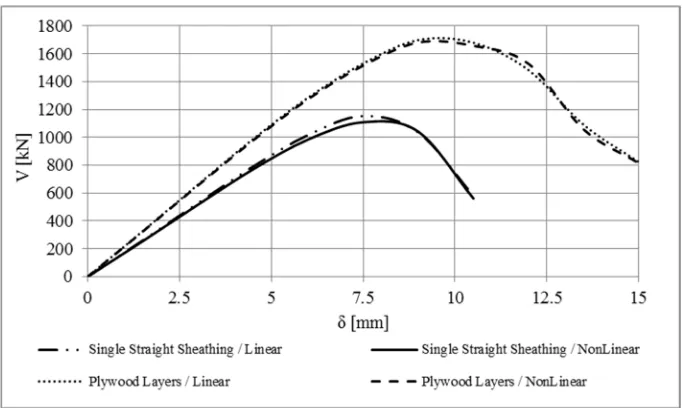
In Fig. 4.5, some of the pushover curves obtained varying the floorboard behavior are reported. With reference to the floorboard configuration labels presented in Fig. 4.4, it was observed that configurations a, b and c were not sensitive to the “constitutive law adopted” for the modeling. In other words, the boards behaved as rigid bodies with all the deformations concentrated in the nails. The behavior of diaphragms with longer boards was instead significantly affected by the flexural deformability of the planks (Fig. 4.5c). In all conditions, the influence of the board shear deformability appeared to be negligible.
The influence of the different floorboard configurations is presented in Fig. 4.6. It can be seen that the use of long boards in a staggered disposition increased the diaphragm in-plane stiffness. This appears to be in contrast with what observed by [Brignola et al. (2008)] where no actual difference was observed between single span disposition, two span staggered disposition and four span staggered disposition. It can also be noticed that a very important role in determining the floor response was played by the nails. In fact a variation in the nailing pattern (adopting 1 nail couple where the board was continuous) produced almost the same effect registered when going from a single span configuration to an eight span staggered disposition. Consequently it is not surprising that a reduction in the floorboard width produced an increase in the diaphragm stiffness, due to the extra nail couples related to the increased number of boards (Fig. 4.7). As one might expect, by considering that the floorboards behaved almost rigidly without involving their deformability (with the exception of configuration e) ), it was observed that
a) b) c)
a variation in the board thickness did not generate appreciable changes in the pushover curve unless quite long planks were adopted.
As regards boundary conditions, analyses (with load acting parallel to the joists) were conducted varying the constraints applied to the external joists. In order to be able to appreciate a possible flexural beam-like behavior, a solution that prevented the external joists from rotating and another one with just a hinge positioned at the joist midspan were investigated. It was observed that model B_5x4 was scarcely affected by such changes in the constraints. The response of model A_10x5, showed that in case of single span flooring (where the boards behave like rigid bodies) the external joists tend to rotate, while in presence of long staggered boards (which exploit their own flexural deformability) the pushover curve was not influenced by the lateral constraint mutation (Fig. 4.8) conversely to what could be expected. Some analyses were also performed hindering the nail deformability in the direction parallel to the load direction. No effects were registered in case of single span floorboards. This means that the nails deformed mainly in the direction orthogonal to the joists. On the other hand when the floorboards were arranged in a staggered configuration the “parallel component” of the nail deformation became significant, even for 2 span boards.
Fig. 4.5 Effect on the pushover curve produced by different assumptions on the plank behavior (Ereal = 10 GPa, Greal = 0.63 GPa)
0 40 80
2 span staggered floorboards
a)
0 50 100 150
δ[mm]
8span staggered floorboards
Isotropic
Orthotropic
G real; E
E real; G
Rigid
∞
∞
c)
(G real, E0/90real)
(ν = 0.3)
0 50 100
0 50 100 150
Fig. 4.6 Pushover curves (load direction parallel to the joists, target displacement = 150 mm)
Fig. 4.7 Influence of the floorboard size on the diaphram behavior
0 20 40 60 80 100 120
0 25 50 75 100 125 150
F o rc e [ k N ]
Midspan displacement [mm]
Pushover curves 8 span staggered
4 span staggered 2 span staggered 4 span 1 span
8 span staggered_1 nail couple 4 span staggered_1 nail couple 2 span staggered_1 nail couple 4 span_1 nail couple
A_10x5 0 10 20 30 40 50 60 70
0 50 100 150
F o rc e [ k N ]
Midspan deflection [mm] 1 span disposition
140 mm x 20 mm 180 mm x 30 mm 200 mm x 20 mm 140 mm x 30 mm 200 mm x 30 mm
B_5x4 0 20 40 60 80 100 120 140
0 50 100 150
Midspan deflection [mm]
8 span staggered disposition
140 mm x 20 mm 140 mm x 30 mm 180 mm x 30 mm 200 mm x 20 mm 200 mm x 30 mm
Fig. 4.8 Pushover curves: effects of the lateral constraint variation (A_10x5)
In order to determine the static scheme that better approximate the behavior of a timber floor subjected to lateral inertial loads, the deformed shape of the FE model was analyzed. The ideal beams taken into account were: a flexural beam with both ends fixed and subjected to uniformly distributed load; a shear beam under a parabolic load distribution (which has the same behavior of a pinned flexural beam under uniformly distributed load) and a shear beam loaded with a uniform load distribution. It should be noted that even if the shapes of the two ideal shear beams seem very similar, the Gd
values derived adopting the two schemes vary of approximately 40%.
Single span floor diaphragms exhibited a clear variation in the deformed curve slope adjacent to the external bays (Fig. 4.9), which might be a prompt to think to a fixed flexural-beam behavior. This was due to the presence on the external joists of 4 nails acting together (in parallel) while, on the internal joists, there were 2 nail couples working in series. The use of 2 nails instead of 4 on the outer joists (this means that every board had 1 nail couple on each of its ends) changed the deformed shape significantly, showing a way more pronounced sag.
It is interesting to notice that, for the “big size” case study (A_10x5), a reduction of the joist spacing from 500 mm to 300 mm, made the deformed shape extremely similar to that of a shear beam under a parabolic load distrib