Design method and experiment of machinery for combined application of
seed, fertilizer and herbicide
Xin Huang
1,2,
Weiwei Wang
3,4,
Zhaodong Li
3,4,
Qingqing Wang
3,
Cunxi Zhu
3,
Liqing Chen
3,4*(1. Key Laboratory of Plant Protection Engineering, Ministry of Agriculture and Rural Affairs, Jiangsu University, Zhenjiang 212013, China; 2. Key Laboratory of Modern Agricultural Equipment and Technology, Ministry of Education, Jiangsu University, Zhenjiang 212013, China;
3. College of Engineering, Anhui Agricultural University, Hefei 230036, China;
4. Anhui Province Engineering Laboratory of Intelligent Agricultural Machinery and Equipment, Hefei 230036, China)
Abstract: This study aimed to resolve the problems of full wheat straw returning to the field, which might readily cause stalk
obstruction, poor sowing quality, and serious weeds at the seedling stage, affecting the growth of maize. Based on the idea of “simultaneous seeding and spraying, closed weeding”, this paper presented a design method for designing a corn seed-fertilizer-herbicide simultaneous operation machine, which focuses on the design of vertical active straw-removing anti-blocking device mechanism, design of nozzle key parameters, nozzle selection, seeding monomer analysis and spatial layout design of seed-fertilizer-herbicide mechanism. In addition, the interrelated formulas were deduced and machine design and field experiment were conducted. The experiment results showed that the average variation coefficient of spray uniformity of machines was 17.70%. The post-experiment weed amount was 8.9%, which was lower than that before sowing, 8.5% lower than that before artificially closed weeding, and 14.3% lower than that in unenclosed weeding area. Moreover, the weeds were less in the working area of the machine, and the growth of corn was better. Compared with manual closed weeding, the average plant height uniformity and average stem diameter uniformity increased by 4.4% and 5.1%, respectively. Compared with unclosed weeding, the average plant height uniformity and average stem diameter uniformity increased by 18.3% and 10.8%, respectively. Overall, the rationality of the design method proposed in this paper was validated, and these can lay a foundation for the research and development of the same type of machine.
Keywords: seed-fertilizer-herbicide, combined application, precision seeding machine, spray device, closed weeding DOI: 10.25165/j.ijabe.20191204.4679
Citation: Huang X, Wang W W, Li Z D, Wang Q Q, Zhu C X, Chen L Q. Design method and experiment of machinery for
combined application of seed, fertilizer and herbicide. Int J Agric & Biol Eng, 2019; 12(4): 63–71.
1 Introduction
Straw mulching offers advantages such as increasing soil fertility, retaining moisture and improving the air pollution caused by straw burning[1-4]. However, full wheat straw returning to the
field could readily account for stalk obstruction, poor sowing quality and serious weeds at the seedling stage, thereby affecting the growth of maize[5-8]. Hence, several domestic and foreign
scholars have comprehensively investigated anti-blocking mechanism and weeding technology of maize no-tillage seeder. The research on anti-blocking mechanism can be divided into active and passive types[9-17], the existing research results show that
the passive stubble breaking disc and active rotating stubble killer,
Received date: 2018-12-05 Accepted date: 2019-06-08
Biographies: Xin Huang, PhD candidate, research interests: modern mechanical
design and theory, Email: [email protected]; Weiwei Wang, PhD candidate,
research interests: conservation tillage techniques and implements, Email: [email protected]; Zhaodong Li, PhD, research interests: mechanized planting technology and equipment for dry farming, Email: [email protected];
Qingqing Wang, Master, research interests: fully mechanized equipment for dryland crops, Email: [email protected]; Cunxi Zhu, Master, research interests: design and research of mechanized conservation tillage equipment, Email: [email protected].
*Corresponding author: Liqing Chen, PhD, Professor, research interests: crop
protection and machinery engineering. College of Engineering, Anhui Agricultural University, Hefei 230036, China. Tel: +86-13966658997, Email: [email protected].
rotary tiller and pulling wheel are the most commonly used structures. In view of the weeding technology, scholars have carried out a lot of research on plant protection machinery and weed suppression. Wang et al.[18] used the method of UAV spray
deposition mass balance to study the detection and distribution characteristics of space pesticides. Qin et al. [19] carried out a
droplet deposition and efficiency study on the control of wheat powdery mildew using a small UAV by collecting droplet mulching in different canopy layers of wheat. Yang et al.[20]
found that different types of sprinklers had different effects on liquid deposition and aphid control. Cui et al.[21] reported that the
spatial layout of sprinklers has a greater impact on the spraying effect, and the appropriate layout of sprinklers can improve the spraying effect. Guo et al.[22] found that wheat straw mulching
had a significant impact on weed germination and quantity in Maize fields, which not only controlled weed germination, but also showed a good control effect. Aladesanwa et al.[23] studied the
effect of sweet potato as a green plant mulch on grass control and yield of maize crops. Compared with random planting, narrow equidistant planting could increase the yield of legume crops by 30%-70%, and inhibit the growth of weeds at the same time[24].
this study presents a design method of corn seed-fertilizer-herbicide simultaneous operation machine. The proposed design method primarily involves the following: (1) clogging of maize seeding under high stubble and full straw mulching; (2) assessing the spatial position relationship of seeding, spraying and other components; (3) discussing the impact of the spatial layout of spraying device on weed suppression. Accordingly, we studied machine design and conducted field experiments. Hence, this study aims to provide new ideas for further enhancing the combined application of no-tillage maize planting and plant protection spraying technology.
2 Structure and working principle of maize seed-
fertilizer-herbicide combined application machine
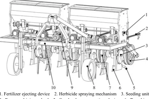
The complete structure of the maize seed-fertilizer-herbicide combined application machine primarily comprised a vertical active straw-removing anti-blocking device, seeding monomer, herbicide spraying mechanism, fertilizer ejecting device, overburden compacting device, limit depth wheel, frame and other components, as shown in Figure 1.
1. Fertilizer ejecting device 2. Herbicide spraying mechanism 3. Seeding unit 4. Repress driving wheels 5. Overburden compacting device 6. Trenching device 7. Vertical active straw-removing anti-blocking device 8. Limit depth wheel 9. Transmission system 10. Frame
Figure 1 Structure diagram of the maize seed-fertilizer-herbicide combined application machine
When the machine works, the tractor power is transmitted to the transmission system of the vertical active straw-removing anti-blocking device through the output shaft, and then to the herbicide spraying mechanism to realize the power transmission. The anti-blocking device generates vertical rotation by power. Then, the swirl straw separation of “cut-pull-throw” in the seeding line was realized. In addition, straw mulching was created between the adjacent two sowing rows, which effectively inhibited the weed growth in non-sowing areas[22]. Then, the trenching
device breaks the soil, the fertilizer ejecting device and seed metering device realize the fertilization and seeding under the wheel drive.
The herbicide spraying mechanism, driven by the power of the tractor output shaft, pumps the herbicide in the herbicide box to the sprinkler head, and completes the closed herbicide application. Notably, the spraying method uses the row-to-row arrangement of the seeding lines to ensure that the herbicide completely covers the seeding area. The combined application machine can complete several agronomic processes, including seed bed preparation, lateral deep fertilization, single seed sowing, soil covering suppression, closed weeding, to realize the simultaneous operation of seed-fertilizer- herbicide.
3 Design method of seed-fertilizer-herbicide combined
application machine
3.1 Design method of vertical active straw-removing anti-blocking device mechanism
In order to solve the problem of corn seeding blocking under high stubble and full straw mulching, the straw displacement anti-clogging device was designed. As shown in Figure 2, the structure primarily includes power components, vertical blades, rotary cutter disc and rotary bearings.
1. Power components 2. Rotary bearings 3. Rotary cutter disc 4. Vertical blades 5. Straw 6. Sowing area 7. Area between sowing
Figure 2 Structural diagram of straw displacement and anti-blocking device
When the anti-blocking device rotates, it moves to reciprocate. The vertical blade rotates relative motion around the center of the cutter disc, and the uniform forward motion of the machine implicates motion. Assuming that at the beginning of the operation, the connection lines of the two ends of the vertical blade coincide with the direction of seeding, the equation of the motion trajectory of the endpoints of the anti-blocking device is as follows:
cos (cos / )
sin sin
z
d
d
z
x R ωt V t R α α λ
y R ωt R α
α ωt
v Rω
V λ
V
= + = +
= =
= =
=
(1)
where, ω is rotating angular velocity of cutter shaft, rad/s; Vd is tangential velocity at the end of blade, m/s; Vz is operation speed, km/h; x, y are coordinates of vertical blade endpoint at any time; α is rotating angle of rotary cutter disc, (°); λ is velocity ratio; t is working time, s; R is rotating radius of anti-blocking device.
Equation (1) shows that when λ>1, the locus of the anti-blocking device is a trochoid, implying that the cutter shaft rotates for one cycle, and the forward distance of the machine is less than 2R, which meets the demand of straw displacement. When λ<1, the cutter shaft rotates for one cycle, the forward distance of the machine is more than 2R, and the anti-blocking device locus is a curtate cycloid, which cannot attain the purpose of straw cleaning and anti-blocking.
the sowing area to the area between sowing. As shown in Figure 3, the layout of active straw-removing anti-blocking device should satisfy the following requirements:
30
2 2
30
z z
z
d z
Vπ πR V
S V t
ω λ n
R H
B R
V V
n
πR R
⎧ = = = =
⎪ ⎪
< ⎪ ⎨ ≤ ⎪ ⎪
= ≥
⎪ ⎩
(2)
where, B is cutter disc width, mm; S is straw disturbance pitch, mm; His seeding row spacing, mm; n is cutter disc speed, r/min.
Figure 3 Schematic layout of straw-removing anti-blocking device
By equations (1) and (2), the following equation can be obtained:
1
sin 1 2
z
S V B B B
R ωR R R R
− ⎛ ⎞ ⎛ ⎞
= ⎜ − +⎟ ⎜ − ⎟
⎝ ⎠ ⎝ ⎠(3)
Let B=kR, take k≤2, k as the overlap coefficient of cutter head diameter and rotation radius, then there are:
(
)
1 1
sin 1 (2 ) 0
S
k k k
R λ
−
= − − − = (4)
Equation (4) shows that, k is proportional to λ, and decreases with the reduction of λ, so that the disturbance pitch S of straw decreases. Of note, the smaller the disturbance pitch, the less amount of straw in the area to be sown. According to document[25], the actual trenching ridge width of sowing is 40-
60 mm, and the lateral fertilization method requires the distance between the fertilizer furrow opener and the seeder furrow opener to be 30-50 mm. To ensure the space position and ridge width of the seeder and fertilizer furrow opener, R is 120 mm. Based on the agronomic requirements, the row spacing H is 600 mm[26], the
operation speed of the seeder is 5-8 km/h, K is 1.5-1.8, B is 216-240 mm, and λ is 2.9-3.5, and the cutter disc speed is 368- 710 r/min.
3.2 Design method of herbicide spraying mechanism
3.2.1 Volume design of the herbicide box
To enhance the efficiency of operation, the volume of the herbicide box should ensure that under the prescribed spraying amount, it can satisfy the simultaneous operation time of a single addition of seeds and fertilizers. During the period, there should be no shortage of herbicide, so the following equation should be satisfied:
z
p p
b z S R Q Z t Q Z
L V
≥ ⋅ ⋅ = ⋅ ⋅ (5)
where, R is volume of herbicide box, L; Q is single sprinklers flow rate, m3/s; Z
p number of sprinklers; t is operation time of single addition of seeds and fertilizers, s; Szis operation area of single addition of seeds and fertilizers, m2; L
b is sowing breadth, m. Refer to standard NY-T650-2002, closed weeding operations using low-volume spray, spray pressure of 0.3 MPa, designed spray volume of 300 L/hm2, reference standard GB/T 6973-2005 and
GB-T 9478-2005 to evaluate the speed of machine operation is 5-
8 km/h. Furthermore, the flow range of single sprinklers is as follows:
3 3
0.03 10 S Z P 0.05 10
p m
Q V L Q
Z T S
− ⋅ ⋅ −
× ≤ = ≥ ×
⋅ ⋅ (6) where, QS is spray volume of designed, L·hm-2; LP is sprinkling width, m; T is operating time per hectare, s; Sm is area per hectare, m2.
Combining the actual farmland operation in Huanghuaihai area, the area of one operation should not be less than 3 acres. Thus, it can be obtained from Equations (5) and (6), when the operating speed is 5 km/h, the volume of the herbicide box is R≥71.5 L, and when the operating speed is 8 km/h, the volume of herbicide box is R≥75.7 L In order to ensure the stability of the machine in the process of operation, the herbicide box is arranged symmetrically on the frame with double herbicide box and uniform distribution. The length, width and height of the single herbicide box were 0.5 m, 0.3 m and 0.3 m, respectively, and the volume was 45 L.
3.2.2 Nozzle design method
In the design of the nozzle, the nozzle section area and section shape exerted significant impact on the atomization effect[27-29].
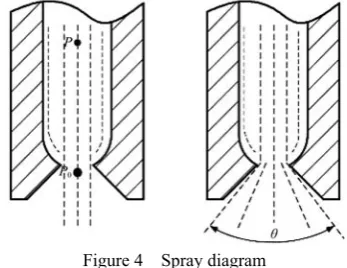
Previously, the nozzle was primarily investigated by experiment. In this section, the section area and section shape of the nozzle are discussed, along with the corresponding design method. Figure 4 presents the spray diagram when the nozzle is working.
Figure 4 Spray diagram
One point P0 at the outlet of the nozzle and one point P inside
the nozzle were located on the same streamline, which can be obtained using the Bernoulli equation:
2 2
0 0
0
2 2
P V P V
Z Z
ρg g ρg g
+ + = + + (7)
where, Z, Z0 is height at point P and P0, respectively, m; P, P0 is
pressure at point P and P0, respectively, Pa; V, V0 is the flow
velocity at point P and P0, respectively, m/s; ρ is fluid density,
kg/m3; g is acceleration of gravity, 9.8 m/s.
By Equation (7):
2
0 2 ( 0) 2( 0) /
V = g z z− +V + P P− ρ (8) But 2g(z–z0)+V2 and2(P–P0)ρare very small and negligible,
if ΔP=P–P0, there is a nozzle outlet velocity:
0 2ΔP V
ρ
= (9)
The flow rate of single nozzle is:
0
2Δ
d p d p
P
Q C S V C S
ρ
= = (10)
where, Q is single nozzle flow rate, m3·s-1; C
d is discharge coefficient, 0-1; Sp is nozzle cross section area, m2; ΔP is nozzle pressure, Pa.
2Δ
p d
Q ρ
S
C P
= (11)
The sectional area of the nozzle can be obtained by equations (6) and (11): Sp=2.46×10⁻⁶ m2.
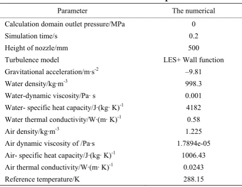
To further determine the impact of nozzle shape on the performance of the nozzle, the different nozzle shape (circle, square and fan shape) with the same cross section was selected as the object. The spray angle is taken as the evaluation index to select the nozzle. Based on the Lattice Boltzmann approach, and being particle based requires no involved meshing processes. In addition, the multiphase flow simulation model of water air nozzle was established by using the fluid analysis software, and the spray angle performance was analyzed. Table 1 presents the simulation environment parameter[30-33].
Table 1 Simulation environment parameters
Parameter The numerical
Calculation domain outlet pressure/MPa 0
Simulation time/s 0.2
Height of nozzle/mm 500
Turbulence model LES+ Wall function
Gravitational acceleration/m·s-2 –9.81
Water density/kg·m-3 998.3
Water-dynamic viscosity/Pa· s 0.001
Water- specific heat capacity/J·(kg· K)-1 4182 Water thermal conductivity/W·(m· K)-1 0.58
Air density/kg·m-3 1.225
Air dynamic viscosity of /Pa·s 1.7894e-05
Air- specific heat capacity/J·(kg· K)-1 1006.43
Air thermal conductivity/W·(m· K)-1 0.0243
Reference temperature/K 288.15
To verify the accuracy of the simulation model, the circular nozzle was taken as the study object, and its spray angle was analyzed by simulation and high-definition photography. The spray angle was compared under the spray pressure of 0.1 MPa, 0.2 MPa and 0.3 MPa, respectively. The results are shown in Figure 5.
a. 0.1 MPa b. 0.2 MPa c. 0.3 MPa
Figure 5 Simulation spray angle and experiment spray angle Based on the chart: under the spray pressures of 0.1 MPa, 0.2 MPa and 0.3 MPa, the simulation and experiment results were similar. Further data analysis revealed that the error was within 10%, verifying the accuracy of the simulation model (Figure 6).
Figure 6 Result of spray angle experiment
Three kinds of sprinklers were tested under a rated working pressure of 0.3 MPa using the simulation model. The results as
shown in Figure 7, under rated working pressure, the spray angles of circular sprinklers, square sprinklers and fan sprinklers were 15°, 37° and 100°, respectively, demonstrating that the spray angle and spray range of the circular nozzle are the smallest, and that the fan nozzle was the largest. Notably, as the spray angle becomes small, the droplet penetration ability becomes strong, whereas as the spray angle becomes large, droplet distribution and uniformity become good[34].
a. Circular nozzle b. Square nozzle c. Fan nozzle Figure 7 Sprinkler simulation diagram
The spatial layout of sprinkler directly affects the field operation effect of the herbicide spraying mechanism. As the herbicide spraying mechanism of the combined machine primarily sprays herbicide on the seeding line, the sprinkling width should fulfill the operating width of the machine. Meanwhile, the composition of the fog curtain should be as uniform as possible and the drift rate of the fog droplets should be as low as possible. Notably, the uniformity of the fog curtain synthesis is affected by the installation height of sprinkler from ground, spray angle and distance between sprinklers. In addition, the height of the sprinkler arrangement exerts a significant impact influence on the droplet drift rate. Furthermore, the droplet drift rate is proportional to the sprinkler height. The higher the sprinkler height is, the larger the droplet drift rate is, and the lower the utilization of the liquid medicine. Based on the agronomic requirements of maize seeding, as the spacing of seeding rows was 600 mm, so the distance between sprinklers was 600 mm too. Based on the multiphase flow simulation model, the simulation analysis of fog curtain synthesis with sprinkler height 450 mm, 500 mm and 550 mm from the ground was carried out. The results are shown in Figure 8.
Sprinkler height from ground is 450 mm
Sprinkler height from ground is 500 mm
The results revealed that the spray uniformity was the best when the spray pressure was 0.3 MPa and the nozzle height was 500 mm.
3.3 Spatial position design method of seed-fertilizer- herbicide mechanism
3.3.1 Motion analysis of the seeding monomer
The seeding unit was connected with a frame through a quadrilateral profiling mechanism, which was equipped with a force-regulating device that can provide a specific force for the seeding monomer and ensure that the depth-limiting wheel is close to the ground in the working process. With the relief of the terrain, the monomer floats up and down through the profiling mechanism to ensure the consistency of the seeding depth. During the operation of the seeding monomer, four main forces are traction, ditch resistance, gravity and wheel resistance. Figure 9 shows the force analysis of the seeding monomer.
Figure 9 Force analysis of seeding monomer
Of these: PX, PY is the traction of the seeding unit; M is the traction torque; G is the gravity of the seeding unit; L is the length of the connecting rod of the profiling mechanism; α is the angle between the connecting rod and the horizontal plane; RX, RY is the resistance of the ditch opener. H1 is the distance from the traction
PX to the connecting rod hinge point; H2 is the distance from the
resistance RX to the connecting rod end; H3 is the distance from the
gravity G to the connecting rod end; H4 is the distance from the
resistance FY to the connecting rod end; H5 is the distance from the
resistance FX to the connecting rod end.
The stress analysis of the sowing monomer in the X and Y directions shows that:
1 2 5
4 3
0 0
( sin ) cos ( sin )
( cos ) ( cos )
X X X
Y Y Y
X X Y X
Y
P R F
P R F
P H R H L α R L α F H L α
F H L α G H L α M
− − = ⎧ ⎪ − − = ⎪ ⎨ + + + + + + ⎪ ⎪ + − + = ⎩ (12)
Based on the motion analysis, the seeding monomer works at a constant speed of V1. At a certain seeding depth, the center of
gravity of the seeding monomer was C0 (X0, Y0). The horizontal
angle between the seeding monomer connecting rod and the frame was α, and the length of the connecting rod was L. Owing to the force, the depth of ditching become shallow, and the angle between the connecting rod and the horizontal plane swung at an angle of α based on β. The position of the center of gravity moved to C1 (X1,
Y1), and the position of the center of gravity is presented as follows:
1 0 1
1 0
[cos( ) cos ] [sin( ) sin ]
x x V t L α β α
y y L α β α
= + − − −
⎧
⎨ = + − −
⎩ (13)
Using the Lagrangian equation, the motion differential
equation and the virtual work equation of the seeded monomer can be obtained as follows:
β
β β β
d T T
θ
dt β β
Mδ θ δ
⎧ ⎛ ⎞− = ⎪ ⎜ ⎟ ⎨ ⎝ ⎠ ⎪ = ⎩ (14)
If I0 is the moment of inertia of seeding monomer and m is the
mass of seeding monomer, then:
2 2 2 2
1 1 0
1 2 5
4 3
1 sin( ) 1 1
2 2 2
( sin ) cos ( sin )
( cos ) ( cos )
β X X Y X
Y
T mv mv Lβ α β mLβ I β
θ P H R H L α R L α F H L α
F H L α G H L α
= − − + +
= + + + + + +
+ − +
(15) When the seeding monomer cannot reach the set seeding depth because of other reasons when working in the field, the reaction force at the crushing wheel can be ignored. The combined Equations (7), (8) and (10) can be written as follows:
1 2 3
1 1 2 3
2
3
cos sin
( )
( )cos sin
( )sin cos
β
X
Y X
Y X
θ c c β c β
c R H H GH
c R L GL α R L α
c GL R L α R L α
= + − ⎧ ⎪ = + − ⎪ ⎨ = − + ⎪ ⎪ = − + ⎩ (16)
As the swing angle of the connecting rod of the copying mechanism is small, there is: sinβ≈β, cosβ≈1–β. Thus, the combined Equations (9) and (11) can be obtained as follows:
1 2 3
2 0
( ) ( )cos sin
( )sin cos
( )sin cos
1 cos
X Y X
Y X
Y X
R H H GH R L GL α R L α
β
GL R L α R L α
GL R L α R L αt
mL I + − + − + = − + ⎛ − − + ⎞ ⎜ ⎟ ⎜ + ⎟ ⎝ ⎠ (17)
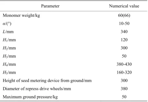
Based on Equation (17), the swing angle of the connecting rod decreases with the increase in weight and rotational inertia of the seeding unit. To evade the excessive swing of the connecting rod during the seeding process, which would affect the stability of the seeding depth, the weight of the seeding unit should not be too small. In addition, the swing angle of the four connecting rods linearly correlated with the horizontal distance from the center of gravity to the connecting rod. With the increase in the distance from the center of gravity to the connecting rod, the swing angle decreases. Moreover, with an increase in horizontal and vertical resistance, the swing angle of the connecting rod increases. Table 2 presents the relevant structural parameters of the seeding monomer. Figure 10 shows that the seeding unit can be designed.
Table 2 Sowing monomer parameters
Parameter Numerical value
Monomer weight/kg 60(66)
α/(°) 10-50
L/mm 340
H1/mm 120
H2/mm 300
H3/mm 50
H4/mm 380-430
H5/mm 160-320
Height of seed metering device from ground/mm 300 Diameter of repress drive wheels/mm 380
1. Seed box 2. Profiling components 3. Seed metering device 4. Repression drive wheel 5. Pressure regulating device
Figure 10 Corn seeding monomer 3.3.2 Interposition relations analysis of mechanisms
The machine adopts side deep fertilization, and as shown in Figure 11. The density of the root system of maize was the densest in the range of 0-100 mm at the initial stage of straw returning[35]. Hence, the distance between the furrowing legs and
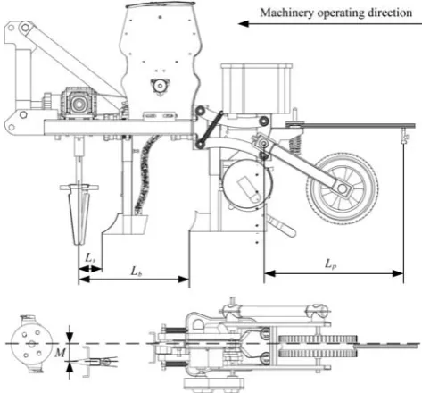
sowing legs M should be 0-100 mm. If M is too small, the former crop straw may be blocked between the ditches. If M is too large, the effect of lateral fertilization would not be apparent. Hence, M is 50 mm.
Figure 11 Side deep fertilization
Figure 12 shows the spatial arrangement of seed-fertilizer- herbicide mechanism. When the machine starts to work, there are:
2 1 2
p b
z z b
H gt
L V t
⎧ =
⎪ ⎨ ⎪ = ⎩
(18)
where, Hp is height of seed metering device from ground, mm; tb is seed falling time, s; Lz is operating distance during tb time, mm.
Figure 12 Schematic diagram of seed-fertilizer-herbicide mechanism
If the seeds and fertilizers fall to the sowing area without inter-agency interference, they should be satisfied:
4
b z
s b
p
L L
R L L
L H
⎧ ≤
⎪ < <
⎨
⎪ >
⎩
(19)
where, Ls is distance between fertilizer ditcher and rotary shaft of anti-blocking device, mm; Lb is distance between seed ditcher and rotary shaft of anti-blocking device, mm; Lp is sprinkler rod length, mm.
From the foregoing paragraphs, Hp is 300 mm, R is 120 mm, Vz is 5-8 km/h, H4 is 380-430 mm. Obtainable by Equations (18) and (19): Lp<350 mm, 120 mm<Ls<350 mm, Lp>430 mm. So,
Lp=340 mm, Ls=130 mm, Lp=450 mm.
4 Experiment and discussion
4.1 Uniformity test of the fog curtain synthesis
The fog curtain synthesis uniformity experiment was carried out based on the standard GB/T 20183.1-2006, and used the spray uniformity as the evaluation index. Under the working pressures of 0.1 MPa, 0.2 MPa and 0.3 MPa, the height between the nozzle and the fog collecting tank was set to 450 mm, 500 mm and 550 mm, and the experiment was conducted 3 times, each test time is 1 min, and 36 recording points of the collecting tank are collected. The uniformity of spray along the axial flow of the mist is expressed by the coefficient of variation. The calculation is as follows:
1 2
2 2
Σ
Σ
Σ( )
Σ( )
100% m
R R R R
R
m m
R R
R R m
G
m m
G W
R
+ + +
= =
− −
= =
= ×
L
(20)
where, R is average; G is standard deviation; W is coefficient of variation, %; R1, R2…Rm is spray volume at each measuring point, mL; m is number of measuring points.
Table 3 presents the results of the spray uniformity experiment, when the spray pressure is 0.3 MPa and the nozzle height is 500mm from the ground, the average coefficient of variation of spray uniformity is smallest, which is 17.70%, verifying the correctness of the proposed method.
4.2 Field experiment
Based on the design method explained above, a maize seed-fertilizer-herbicide mechanism (as shown in Figure 13) was designed and field experiments were conducted in this study.
As shown in Figure 14, the field experiment was conducted in the experimental field of Anhui Agricultural University, Xiaoxinji Township, Mengcheng County, Anhui Province, on June 7, 2018. The former crop of the field was wheat, and the harvesting method was a harvester equipped with straw crusher. The stubble height was 30 mm, and the average straw coverage was 1.49 kg/m2. The
spraying herbicide used in the experiment was a mixed aqueous solution of nicosulfuron and atrazine, and the maize variety Zhongza 598 was sown.
Table 3 Spray uniformity test
Pressure /MPa
Height
/mm Frequency
Coefficient of variation/%
Average coefficient of variation/%
0.1
450
1 33.06 32.69 2 32.42 3 32.60
500
1 27.26 26.89 2 26.83 3 26.57
550
1 29.92 29.98 2 29.01 3 30.03
0.2
450
1 27.59 26.28 2 25.53 3 25.72
500
1 22.25 22.87 2 23.62 3 22.76
550
1 22.26 21.96 2 22.06 3 21.55
0.3
450
1 21.59 19.31 2 16.11 3 20.22
500
1 18.6 17.70 2 16.96 3 17.52
550
1 22.48 22.83 2 23.27 3 22.74
Figure 13 Maize seed-fertilizer-herbicide mechanism Before sowing, the weeds in the test field were collected with a metal frame of 1 m×1 m using the nine-point sampling method and
the weeds were counted. Then the sowing experiment was conducted. After 10 d, the weeds in test group A, B and C were recounted.
a. Straw of former crop b. Growth of maize Figure 14 Field experiment
To investigate the relationship between closed weeding and maize growth, at 10 d after sowing test, 1 m×1 m sampling area was selected by using the nine-point sampling method in test groups A, B and C, and the maize plant height uniformity and stem diameter uniformity were used as evaluation indicators to evaluate maize growth. The formula for calculating the uniformity is as shown in Equation (21), and Table 4 presents the results of the field experiment.
1 2
2 2
Σ
Σ
Σ( )
Σ( )
n i
i i
x x x x
x
m m
x x
x x m
J
m m
x M
J
+ + +
= =
− −
= =
=
L
(21)
where, x is average value of a character; J is standard deviation of a character, M is uniformity; x1, x2…xn is the character values of each measuring point, mm; m is number of measured points.
4.3 Results and discussion
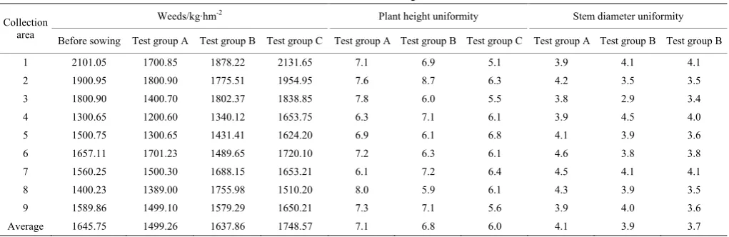
As can be seen from Table 4:
(1) The average amount of weeds before sowing was 1645.75 kg/hm2, the average amount of weeds in test groups A, B
and C was 1499.26 kg/hm2, 1637.86 kg/hm2, and 1748.57 kg/hm2,
respectively. The number of weeds in test group A decreased by 8.9% compared with that before sowing, which was 8.5% lower than that in test group B and 14.3% compared with test group C. The number of weed in test group B was the same as before planting, and the relative test group C decreased by 6.3%. Test group C had the highest amount of weeds, an increase of 6.2% compared to pre-planting.
Table 4 Result of field experiment
Collection area
Weeds/kg·hm-2 Plant height uniformity Stem diameter uniformity Before sowing Test group A Test group B Test group C Test group A Test group B Test group C Test group A Test group B Test group B
1 2101.05 1700.85 1878.22 2131.65 7.1 6.9 5.1 3.9 4.1 4.1
2 1900.95 1800.90 1775.51 1954.95 7.6 8.7 6.3 4.2 3.5 3.5
3 1800.90 1400.70 1802.37 1838.85 7.8 6.0 5.5 3.8 2.9 3.4
4 1300.65 1200.60 1340.12 1653.75 6.3 7.1 6.1 3.9 4.5 4.0
5 1500.75 1300.65 1431.41 1624.20 6.9 6.1 6.8 4.1 3.9 3.6
6 1657.11 1701.23 1489.65 1720.10 7.2 6.3 6.1 4.6 3.8 3.8
7 1560.25 1500.30 1688.15 1653.21 6.1 7.2 6.4 4.5 4.1 4.1
8 1400.23 1389.00 1755.98 1510.20 8.0 5.9 6.1 4.3 3.9 3.5
9 1589.86 1499.10 1579.29 1650.21 7.3 7.1 5.6 3.9 4.0 3.6
(2) The average plant height uniformity of the test group A was 7.1, and the average stem diameter uniformity was 4.1. The average plant height uniformity of test group B was 6.8, and the average stem diameter uniformity was 3.9. The average plant height uniformity of test group C was 6.0, and the average stem diameter uniformity was 3.7. Compared with test group B, the average plant height uniformity and average stem diameter uniformity of test group A were increased by 4.4% and 5.1%, respectively. Compared with test group C, the average plant height uniformity and average stem diameter uniformity of test group A were increased by 18.3% and 10.8%, respectively.
Notably, the impact of closed weeding by machine is better than that of manual weeding because under the same amount of spray, the spray uniformity of machine is better and the coverage of weeds is broader, rendering the effect of weeding more significant than that of manual weeding. Thus, the smaller number of weeds in the experimental group, the better the growth status of corn because fewer weeds compete for less growth resources. Hence, maize seedlings in experimental group A were better than those in the experimental group B and C in both plant height uniformity and stem diameter uniformity.
The field experiment revealed that the combined application machine was used for sowing operation, which could decrease the number of weeds in the early stage of corn growth and enhance the initial growth of corn compared with manually closed weeding and no weeding. The impact of artificially closed weeding was not as good as that of machine closed weeding, and machine closed weeding could decrease the manual operation and enhance the efficiency of cultivation, thereby verifying the validity and rationality of the design method.
5 Conclusions
This study proposed a design method of maize seed-fertilizer-herbicide combined application machine and focused on the design of vertical active straw-removing anti-blocking device mechanism, design of nozzle key parameters, nozzle selection, seeding monomer analysis, and spatial layout design of seed-fertilizer-herbicide mechanism. In addition, the interrelated formulas were simplified. These can lay a foundation for the research and development of the same type of machine.
The field experiment revealed that the average uniformity variation coefficient of spray was 17.70%; The weed number after operation was 8.9% lower than that before sowing, 8.5% lower than that before artificial closed weeding, and 14.3% lower than that in unenclosed weeding area. The number of weeds in the working area of the machine was smaller, and the growth of corn was better. Compared with artificially closed weeding, the average plant height uniformity and average stem diameter uniformity were increased by 4.4% and 5.1%. Furthermore, compared with unclosed weeding, the average plant height uniformity and average stem diameter uniformity were increased by 18.3% and 10.8%. Overall, the rationality of the design method of this paper is validated.
Acknowledgements
This research was financially supported by the Special Fund of Ministry of Agriculture of China for Public Welfare Projects (No.201503136) and Science and Technology Project in Anhui Province (NO: 1604a0702035).
[References]
[1] Gao H W, He M, Shang S Q, Fang X Q. High yield and benefit system for conservation tillage. Transactions of the CSAM, 2013; 4(6): 35–38, 49. (in Chinese)
[2] Ding J L, Wu J C, Yang Y H, He J Q, Feng H. Simulation of effects of tillage pattern transformation on soil water conservation with RZWQM model. Transactions of the CSAM, 2016; 47(4): 136–145. (in Chinese) [3] Cao Y F, Zhang H, Liu K, Lv J L. Decomposition characteristics of crop
residues among different agricultural treatments. Transactions of the CSAM, 2016; 47(9): 212–219. (in Chinese)
[4] Luo X W, Liao J, Hu L, Zang Y, Zhou Z J. Improving agricultural mechanization level to promote agricultural sustainable development. Transactions of the CSAE, 2016; 32(1): 1–11. (in Chinese)
[5] Qi Y Z, Zhen W C, Li H Y. Allelopathy of decomposed maize straw products on three soilborn diseases of wheat and the analysis by GC-MS. Journal of Integrative Agriculture, 2015; 14(1): 88–97.
[6] Song P F, Mao P, Li H P, Wang Z C, Luo M H. Effects of straw returning on the occurrence degree of summer maize pests. Journal of Henan Agricultural University, 2014; 48(3): 334–338, 347. (in Chinese) [7] Zhao X L, Ren Y X, Zhao X, Pu C, Zhang X Q, Zhang H L. Advances in
ecological effects of residue retained in North China Plain. Crops, 2017; (1): 1–7. (in Chinese)
[8] Mu C A, Li Z. Effects of returning crop stalks to the field on the crop diseases and pests in Huang-Huai area and its control measures. Journal of Anhui Agri. Sci. 2016; 44(11): 179–180, 189. (in Chinese)
[9] Wang Q J, He J, Li H W, Lu C Y, Rasaily G R, Su Y B. Design and experiment on furrowing and anti-blocking unit for no-till planter. Transactions of the CSAE, 2012; 28(1): 27–31. (in Chinese)
[10] Yang L, Zhang R, Liu Q W, Yin X W, He X T. Row cleaner and depth control unit improving sowing performance of maize no-till precision planter. Transactions of the CSAE, 2016; 32(17): 18–23. (in Chinese) [11] He J, Li H W, Li H, Zhang X M, Zhang X R. No-till planter with
reciprocating-cutter for wheat permanent raised beds cultivation. Transactions of the CSAE, 2009; 25(11): 133–138. (in Chinese)
[12] Zhang X R, Li H W, He J, Wang Q J, Zhang X M. Comparative experiment on anti-blocking mechanism for wheat no-till planter. Transactions of the CSAM, 2010; 41(2): 73–77. (in Chinese)
[13] Jia H L, Jiang X M, Yuan H F, Zhuang J, Zhao J L, Guo M Z. Stalk cutting mechanism of no-tillage planter for wide/narrow row farming mode. Int J Agric & Biol Eng, 2017; 10(2): 26–35
[14] Liao Q X, Gao H W, Wang S X, Su C X. Experimental study on sawtooth anti-blocking mechanism for no-tillage planter. Transactions of the CSAM, 2003; 34(6): 91–95. (in Chinese)
[15] Vamerali T, Bertocco M, Sartori L. Effects of a new wide-sweep opener for no-till planter on seed zone properties and root establishment in maize (Zea mays L.): A comparison with double-disk opener. Soil & Tillage Research, 2006; 89(2): 196–209.
[16] Roy K C, Haque M E, Justice S, Hossain I, Meisner C A. Development of Tillage Machinery for Conservation Agriculture in Bangladesh. AMA-AGR MECH ASIA AF, 2009; 40(2): 58–64.
[17] Magalhães P S G, Bianchini A, Braunbeck O A. Simulated and Experimental Analyses of a Toothed Rolling Coulter for Cutting Crop Residues. Biosystems Engineering, 2007; 96(2): 193–200.
[18] Wang C L, He X K, Wang X N, Wang Z C, Wang S L, Li L L, et al. Testing method and distribution characteristics of spatial pesticide spraying deposition quality balance for unmanned aerial vehicle. Int J Agric & Biol Eng, 2018; 11(2): 18–26.
[19] Qin W C, Xue X Y, Zhang S M, Gu W, Wang B K. Droplet deposition and efficiency of fungicides sprayed with small UAV against wheat powdery mildew. Int J Agric & Biol Eng, 2018; 11(2): 27–32.
[20] Yang X W, Zhou J Z, He X K, Herbst A. Influences of nozzle types on pesticide deposition and insecticidal effect to wheat aphids. Transactions of the CSAE, 2012; 28(7): 46–50. (in Chinese)
[21] Cui J, Yang X, Liu J F, Li J P. Setting and study on nozzle spacing of spray rod type of orchard and nursery spraying machine. Journal of Agricultural Mechanization Research, 2014; 36(5): 184–187. (in Chinese) [22] Guo X, Jin Y M, Lian H M, Wang J. Effect of wheat stalk covering on
weed germination and yield of summer corn. Journal of Anhui Agricultural Sciences, 2007; 9: 2584+2596. (in Chinese)
[24] Dusabumuremyi P, Niyibigira C, Mashingaidze A B. Narrow row planting increases yield and suppresses weeds in common bean (Phaseolus vulgaris L.) in a semi- arid agro- ecology of Nyagatare, Rwanda. Crop Protection, 2014; 64(3): 13–18.
[25] Wang W W, Zhu C X, Chen L Q, Li Z D, Huang X, Li J C. Design and experiment of active straw-removing anti-blocking device for maize no-tillage planter. Transactions of the CSAE, 2017; 33(24): 10–17. (in Chinese)
[26] Chen L Q, Wang P P, Zhang P, Zheng Q, He J, Wang Q J. Performance analysis and test of a maize inter-row self-propelled thermal fogger chassis. Int J Agric & Biol Eng, 2018; 11(5): 100–107.
[27] Han Q L, Ma Y. Influence of nozzle structure on high pressure water jet and optimization design of nozzle structure parameter. Journal of National University of Defense Technology, 2016; 38(3): 68–74. (in Chinese)
[28] Yang M G, Xiao S N, Kang C. Influence of Outlet Profile on Performance of Central-body Nozzle. Fluid Machinery, 2011; 39(5): 13–19. (in Chinese)
[29] Wang X F, Li F, Zhao A W, Wu J. Computational simulation of the effect of nozzle export section shape on cold spraying technology for
material modification. Materials for Mechanical Engineering, 2006; 30(12): 84–86. (in Chinese)
[30] Xu X G. Research on the effect of lateral wind and longitudinal spacing on trucks in a platoon. Jilin University, 2016. (in Chinese)
[31] Zhang J M, He X L. Application of lattice Boltzmann method to multiphase flow. Chinese Journal of Hydrodynamics (Series A), 2017; 32(5): 531–541. (in Chinese)
[32] Meng Z F, Jiang J, Li Y H, Fu X Q. Three-dimensional transient simulation of filling and draining processes in gravity flowed pipes based on Lattice Boltzmann method. China Rural Water and Hydropower, 2017; 1: 130–134. (in Chinese)
[33] Fu Y S, Qian J. Mesh-free numerical simulation of static aerodynamic characteristics on crescent-shape iced power transmission line. Journal of Guizhou University (Natural Sciences), 2016; 33(6): 38–42. (in Chinese) [34] Fan X B, Deng W, Wu G F. Research progress of spray drift control
technology. Journal of Agricultural Mechanization Research, 2016; 38(6): 1–9. (in Chinese)