Vol. 40, No. 1 (2018) 52-65, DOI: 10.24874/ti.2018.40.01.04
Tribology in Industry
www.tribology.rsExperimental Investigation on Tool Wear Behavior
and Cutting Temperature during Dry Machining of
Carbon Steel SAE 1030 Using KC810 and KC910
Coated Inserts
Y. Tamerabet
a, M. Brioua
a, M. Tamerabet
a,b, S. Khoualdi
aa Department of Mechanics, Faculty of Technology, University of Batna 2, Algeria,
b Department of Mechanics, Faculty of Sciences and applied Sciences, University of Bouira, Algeria.
Keywords:
Cutting parameters Carbide inserts Dry machining Hard coating Wear behavior
A B S T R A C T
The removal of cutting fluids and lubrication in dry machining operations requires a good knowledge and full control of all the mechanisms that lead to tool damage. In order to optimize dry machining operations, it is necessary to clearly identify the wear patterns, determine the contact conditions and define the relationship between the contact parameters and the operating conditions. The idea is to choose optimal cutting conditions which lead to the best contact conditions limiting the triggering or aggravation of wear phenomena. The purpose of this paper is to determine the impact multilayer coatings and cutting parameters on tool wear and temperature at the tool-chip interface for two types of coated carbides (KC810 and KC910 Commercialized inserts) during dry turning operation of carbon steel SAE 1030, in order to determine the ideal parameters and guarantee the best performances of the cutting tools. Cutting temperature, Crater and Flank wear have been systematically recorded in order to determine their influence on tool life time. To ensure the optimum choice of machining conditions; the TAGUCHI method associated to multi-factorial method were applied to plan the experiments. It has been noted that cutting speed was the most influential factor on temperature and wear evolution. We noted also that the KC810 insert was more suitable for machining of SAE 1030 Carbon Steel; where The best life time was registered (T=228 min). The KC810 inserts offer 30 min of additional machining time for the same work conditions.
© 2018 Published by Faculty of Engineering Corresponding author:
Y. Tamerabet
Department of Mechanics, Faculty of Technology, University of Batna 2, Algeria.
E-mail: t_yacine_2004@msn.com
1. INTRODUCTION
Because of environmental and economic constraints, the progress and development of
the industrial sector; machining is now part of the interests of researchers and industrialists. In particular, dry machining, which represents one of the most recent processes and make it
R
ES
EA
R
possible to obtain parts with roughness and precision closer to those resulting from the grinding process. The control of machining process requires good knowledge, understanding and full control of all the mechanisms involved in the cutting zone [1-3].
During cutting process, many parameters such as temperature, residual constraints, cutting efforts, machined and cutting tool materials, cutting parameters etc., were frequently subjected to many researches for various machining and cutting processes (turning; milling: drilling etc.) in order to determine and understand the impact of the these factors on tool’s life; progression and evolution of wear and the quality of finished work-pieces [1,4-8].
The mechanical energy of the cutting process due to the plastic deformation at the primary shear zone and at the tool-chip interface is converted into heat which is absorbed by the generated chip (70 %), the work-piece (20 %) and the cutting tool (10 %), several researches have shown that a large amount of this heat is dispersed between the chip and the environment, while the rest is transferred to the work-piece and cutting tool [9,10].
However, this small amount of heat transferred to the tool (10 % of the total heat rate) is sufficient enough to create high temperatures close to the cutting edges, which can even reach the threshold of 1100 ° C [1,5,8].
The effects of cutting temperature, particularly when it is high, are mostly harmful to the cutting tool [11,12]. The major portion of the heat is taken away by the chips. The potential negative effects of the high cutting temperature on cutting edge are: Rapid tool wear; which reduces tool life, Plastic deformation of cutting edges, Thermal flaking and fracturing of cutting edges due to thermal shocks and Built up edge formation [13].
Temperature estimation is one of the most difficult and complicated procedures in metal cutting operations. The measurement of this temperature is very difficult because the heat in the region is very close to the cutting edge, the complexity of the geometry of the tool and the continuous movement during the machining operation.
The knowledge of the cutting temperature is very important because it has a great influence in the choice of materials and optimal conditions of machining [5,13].
Temperature measurement techniques include Conventional experimental methods such as infrared pyrometer, integrated thermocouples, natural thermocouples, part cutting tool and infrared (CDD) and the use of thermo-sensitive paint, as well as metallographic method based on metal microstructure or micro-hardness variations are generally the most widely used methods for measuring and identifying the temperature field. [2,5,9,11].
The thermocouples method even it does not permit the direct measurement of the temperature at the cutting edge of the tool, but allow an average temperature value to be given in the thermally affected area between tool and work-piece [5].
The generated temperature at the Tool-Chip-Working-piece interface has a significant influence on the machining factors; it contributes in the same time to the increase of wear and the diminution of the cutting tool life and gives rise to a thermal damage of the cutting tools, which results the modification of the work-piece and tool material’s properties [11,13-15].
Because of high rate of friction between rake face and the workpiece; high temperatures are generated leading to critical wear on the tool surface, short life and poor surface integrity, which generally influence negatively on productivity and quality of final products [4]. Therefore, the identification of the field of the cutting temperature is a very important factor to a good quality of the finished products.
Tool Wear is a destructive process for the superficial layers, which leads to the continuous and progressive modification of the shapes and surface quality of work-pieces. It affects also tool geometry, cutting temperature, cutting efforts, precision and roughness of machined parts. It results primarily from the tearing of small metal particles from the main and auxiliary flank faces [8,16].
magnitude and the way it evolves. Wear is defined as the loss of material on an asperity or a micro-contact, or on a smaller scale, up to the molecular or atomic detachment mechanism, on the other hand, the rupture is a large-scale damage than wear, and it occurs suddenly, there is a continuous spectrum of damage from the micro wear scale to the coarse breaking [16,17].
The tool-chip contact under dynamic friction causes intense plastic deformation, mainly in shear, accompanied by a high temperature rise which can lead to premature wear of the cutting tool (secondary shear zone) [11,13,18].
The tribological phenomena encountered in this area are complex. A third shear zone (tertiary shear zone) due to the tool-tool contact affects the integrity of the machined surface as well as the undercut wear of the tool. The interaction between the tool and the machined material strongly depends on the thermo-mechanical behavior at the tool-chip interface which varies in a complex manner with the cutting conditions [1,9,11,18].
Tool manufacturers are particularly interested in the development of cutting tool coatings where more than 80 % of the machining applications are now made with coated tools [1,6]. Among the coatings available on the market, hard coatings based on Titanium are the most widely used. They have a tendency to improve wear resistance in many applications. TiN and TiC, monolayer and multilayer coatings of carbide inserts are currently widely used for the machining of hard metals such as tool steels and hardened cast iron [19]. The deposition of the coatings on a carbide substrate results in a decrease of the cutting forces and the flank wear of tools [6].
The low material removal rates and the very limited tool life are the mostly encountered problems during dry machining [7]. The analysis of the morphology of wear is an investigation technique that has become widely used in the research of metal cutting [8]. It should be noted that wear of the cutting tools is manifested in much more difficult working conditions than those of the machine parts [20]. The most dominant mechanism of wear is adhesion (around 80 %), followed by abrasion. The contribution of diffusion is negligible (less than 1 %) [21].
The lifetime of a tool is limited by both flank and crater wear. The mechanical damage of the cutting tools (abrasion, cracking, initiation of rupture and fatigue) is particularly independent of temperature [22]. The lifetime of cutting tools, for relatively severe cutting conditions, is improved by the application of certain coatings, correlated with the decrease in flank wear. The damaged tool areas show the influence of the coating on the cutting area of the tool and reveal the good performance of the coated tools [22-25]. The tool life criterion was based on the ISO standard 3685: [8,15,26,27].
H. Çalışkan et al. [28] In order to increase the machinability of Ti6Al4V alloy; aCN/TiAlN coating was deposited on carbide cutting tools. It has been revealed that abrasive wear and adhesive wear were dominant tool failures on the coated tools and wear resistance was improved by 15 % when using aCN/TiAlN coated carbide.
X. Chen et al. [29] have conducted a comparable study between cermet tool and multilayer coated carbide l, it has been noted that cermet tools have shown a better wear resistance at lower depth of cut, The crater wear resistance was improved by the high thermal conductivity of the cermets and the low cutting forces, while the coated tools have sustained a very severe crater wear. It has been also noted that the best quality of finished surface was insured by coated tools. In term of thermal stress the cermets showed better performances because of their high thermal conductivity and low cutting forces.
According to T. Yang et al. [30] in their research the best flank wear resistance was obtained for the inserts with Mo2C addition; and the addition of Mo2C has improved also the wear resistance in term of abrasion, adhesion and diffusion, but oxidation wear has not yet reduced.
Failure patterns of coated carbide tool were investigated by high-speed face milling of the hardened steel SKD11F by Gong et al. [31]. They have indicated that rupture was the dominant failure mode of coated carbide tool. It has been concluded that the variation of cutting speed has an important influence on the pattern of the morphology of fatigue fracture and surface roughness.
intermediate Alumina layer were compared to those of low content PCBN tool during hard machining [32], it has been revealed that the coated carbide tool can do better than PCBN in machining within a certain range of cutting speeds (impact of cutting temperature). It has been noted also that CVD coated carbides had a longer life than PCBN tools with an advantage to PCBN tools in the cases where high precision and dimensional accuracy are required, it is recommended to use PCBN tool because of the low rate of wear in the earlier stages of wear.
The Multi-factorial method associated to TAGUCHI technique [33,34] was implemented for planning the series of machining experiments. Crater and flank wear morphology of cutting tools was examined and observed using adequate means and devices of investigations. Cutting temperature, Crater and Flank wear have been systematically recorded in order to determine their influence on tool life time. To ensure the optimum choice of machining conditions; Temperature and wear evolutions were assessed and plotted graphically and the crater and flank wear aspects were observed using optical microscope.
The aim of this paper is to determine the impact multilayer coatings and the influence of cutting parameters on the temperature at the interface tool-chip and the life of a cutting tool during an operation machining of carbon steel SAE 1030 using commercialized carbide inserts (KC810 and KC910) coated respectively with TiN+Ti(C,N)+TiN and TiC+Al2O3 in order to determine the ideal parameters and guarantee the best performances of the cutting tools.
2. EXPERIMENTAL PROCEDURE
Experiment tests were carried in order to measure the mean temperature and determine the wear pattern of the cutting tools during machining process.
2.1 Material and tools
In order to satisfy the complex and random character of cutting process, the tests were carried out according to the traditional method of long tests duration associated with the TAGUCHI method. The tests were carried out on
cylindrical bars of carbon Steel SAE 1030 used for fabrication of transmission spindles; Chemical composition and physical properties are shown on Тable 1.
Table 1. Chemical composition and physical properties of carbon steel SAE 1030.
Chemical Composition wt.%: 0.29%C, 2.45%Cr, 0.70%Mn, 0.408%Mo, 0.312%Si, 0.188%V, 0.185%Cu, 0.104%Ni, 0.008%Zn and 0.0002%Mg; Remain % Fe
Physical Properties Value in metric unit
Density 7.872 *10³ kg/m³
Modulus of elasticity 200 GPa
Thermal expansion (20 ºC) 11.7*10-6 ºCˉ¹
Specific heat capacity 486 J/(kg*K)
Thermal conductivity 48.7 W/(m*K)
Tensile strength 525 MPa
Yield strength 440 MPa
Elongation 12 %
Hardness Rockwell B 80 RB
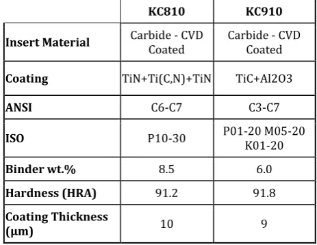
Table 2. Properties of cutting inserts used in the machining tests [35,36].
KC810 KC910
Insert Material Carbide - CVD Coated Carbide - CVD Coated
Coating TiN+Ti(C,N)+TiN TiC+Al2O3
ANSI C6-C7 C3-C7
ISO P10-30 P01-20 M05-20 K01-20
Binder wt.% 8.5 6.0
Hardness (HRA) 91.2 91.8
Coating Thickness
(µm) 10 9
The machined specimens have the following dimensions: 300 mm of length and 60 mm of diameter, to allow a progressive engagement and release of the cutting tools, considering their brittleness, a bevel of 45° was carried out at the entry and the exit of work-piece.
Machine tool: Parallel lathe conventional TOS
TRENCIN, model SN40, EP 1500, with a power of 6.6 KW and a range of speed between 22.5 and 2000 rev/min.
Cutting tools: The cutting tools used in the
coated Carbide inserts type TNUN KC810 and KC910; fabricated by KENNAMETAL INC; assembled on a tool holder TFTR- 16-3 R 177.1-252516 of the SANDVIK Company. The properties of the inserts are shown on Table 2.
2.2 Measuring devices
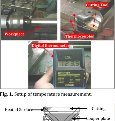
The experimental approach is based on the instrumentation of a cutting insert and tool holder by a thermocouple connected directly to a digital display thermometer GTH 1160; in order to record easily the local temperature readings during the cutting process (Figs.1 and 2).
Workpiece
Cutting Tool
Digital thermometer
Thermocouples
Fig. 1. Setup of temperature measurement.
Heated Surface
Thermocouples
Cooper plate Cutting
insert
Fig. 2. Illustration of the thermocouples setup position on the tool holder.
The thermocouple setup consists of a thin copper plate 0.3 mm on which is welded K thermocouple wires of 0.35 mm diameter (Fig. 2), the two wires of this thermocouple were connected to a digital thermometer held at room temperature. The thermocouples are located sufficiently far from the cutting area so as not to be influenced by variations in the tool-chip contact zone.
It must, however, be placed closer enough to have the maximum accuracy in estimating the
temperature. For recording the required values of the wear profile evolution at the cutting edge; Flank and crater wear were systematically observed and measured after each cutting sequence using an optical microscope. The depth of the crater wear was measured using a 1/1000 mm dial gauge with a conical feeler gauge.
The cutting parameters chosen for the machining experiments are shown on Тable 3.
Table 3.Cutting parameters used in the machining tests. Cutting mode parameters Range of tests
Cutting speed V (m/min) 90, 120 and 250 Feed rate f (mm/rev) 0.11, 0.14 and 0.2
Depth of cut a (mm) 0.5, 1.0 and 1.5
3. RESULTS AND DISCUSSIONS
The experiments have been carried out in order to determine the evolution and the variation of measured temperatures during cutting process for the different parameters of the cutting mode and its relationship with the type of coating; wear profile evolution and tool life duration for the utilized cutting inserts and the impact of cutting parameters on wear behavior. All the tests have been repeated three times.
The results of the tests were graphically plotted as a function of cutting time for the two types of inserts tested in order to define the ideal parameters for the machining of the SAE 1030 steel using coated carbide inserts (KC810 & KC910).
3. 1 Temperature results
The graphics on Figs. 3-5 indicate that the tool temperature evolves and increases accordingly with the increase of cutting parameters (cutting speed, feed rate and depth of cut). The cutting speed seems to be the most effective and influential parameter in assessing the temperature rise [37].
to conclude that both types of coatings did not have a major impact on heat dissipation during machining process and did not show satisfying results in term of temperature resistance and therefore a protective capacity against high cutting temperatures; this lead to conclude that the coating has no significant influence on the thermal behavior of the tool during a continuous machining process as turning. This result is in accordance with experimental investigations made by Rech et al. [9].
0 10 20 30 40 50 60 70 80 90 100 110 100 120 140 160 180 200 220 240 260
Cutting speed (V) (m/min)
- KC 810 insert - KC 910 insert 90 (m/min) 90 (m/min) 120 (m/min) 120 (m/min) 250 (m/min) 250 (m/min)
Cutting Time (Second)
C u tt in g t e m p e r a tu r e ( °C )
a = 0,5 (mm) ; f = 0,11 (mm/rev)
0 10 20 30 40 50 60 70 80 90 100 110 150 165 180 195 210 225 240 255 270 285 300 315 330
Cutting speed (V) (m/min)
- KC 810 insert - KC 910 insert 90 (m/min) 90 (m/min) 120 (m/min) 120 (m/min) 250 (m/min) 250 (m/min)
Cutting Time (Second)
a = 1,5(mm) , f = 0,2 (mm/rev)
C u tt in t e m p e r a tu r e ( °C )
Fig. 3. Impact of cutting speed on transferred temperature to cutting tool for different depths of cut and feed rates.
It has been stated that the cutting temperature increases progressively with the increase of the cutting speed for all the combinations of cutting parameters, which confirms the fact of the significant effect of the cutting speed on the variation of the temperature and the heat transfer in turning process at the tool-chip interface and consequently on the wear behavior and the life of
the cutting tools by promoting the phenomenon of thermal damage, diffusion and adhesion which influence negatively on finished surfaces of the workpiece.
0 10 20 30 40 50 60 70 80 90 100 110 150 165 180 195 210 225 240 255 270 285 300 315 330 345
Depth of cut (a)
- KC 810 insert - KC 910 insert 0.5 (mm) 0.5 (mm) 1.0 (mm) 1.0 (mm) 1.5 (mm) 1.5 (mm)
C u tt in g t e m p e r a tu r e ( °C )
Cutting time (Second)
V = 250 (m/min) , f = 0,2(mm /rev)
0 20 40 60 80 100 120 140 160 180 200 220 240 120 135 150 165 180 195 210 225 240 255 270 285 300
Depth of cut (a)
- KC 810 insert - KC 910 insert 0.5 (mm) 0.5 (mm) 1.0 (mm) 1.0 (mm) 1.5 (mm) 1.5 (mm) V = 90 (m/min) , f = 0,11 (mm /rev)
Cutting time (Second)
C u tt in g t e m p e r a tu r e ( °C )
10 20 30 40 50 60 70 80 90 100 110 165 180 195 210 225 240 255 270 285 300 315 330 345
Feed rate f (mm/rev)
- KC 810 insert - KC 910 insert 0,11 0,11 0,14 0,14 0,20 0,20 V = 250 (m/min) , a = 1,5(mm)
Cutting time (Second)
C u tt in g t e m p e r a tu r e ( °C )
0 10 20 30 40 50 60 70 80 90 100 110 130 140 150 160 170 180 190 200 210 220 230 240
Cutting time (Second)
C u tt in g t e m p e r a tu r e ( ° C )
Feed rate f (mm/rev)
- KC 810 insert - KC 910 insert 0,11 0,11 0,14 0,14 0,20 0,20 V = 90 (m/min) , a = 0,5 (mm)
Fig. 4. Impact of depth of cut on transferred temperature to cutting tool for different cutting speeds and feed rates.
Whereas it was observed that the temperature increases quickly in the first seconds of cutting process (140 °C during the first 10 Sec then 160 °C at 15 sec of machining (Fig. 3: V=90 (m/min),
a=0.5 (mm) and f=0.11 (mm/rev)) due to the important surface of contact and the high pressure exerted by the cutting tool on workpiece, then it pretends to become quite steady with a lower increasing rate (170 °C at 30 sec and to 180 °C at 100 sec of machining (Fig. 3:
0 10 20 30 40 50 60 70 80 90 100 110 150 165 180 195 210 225 240 255 270 285 300 315 330 345
Depth of cut (a)
- KC 810 insert - KC 910 insert 0.5 (mm) 0.5 (mm) 1.0 (mm) 1.0 (mm) 1.5 (mm) 1.5 (mm)
C u tt in g t e m p e r a tu r e ( ° C )
Cutting time (Second) V = 250 (m/min) , f = 0,2(mm /rev)
0 20 40 60 80 100 120 140 160 180 200 220 240 120 135 150 165 180 195 210 225 240 255 270 285 300
Depth of cut (a)
- KC 810 insert - KC 910 insert 0.5 (mm) 0.5 (mm) 1.0 (mm) 1.0 (mm) 1.5 (mm) 1.5 (mm) V = 90 (m/min) , f = 0,11 (mm /rev)
Cutting time (Second)
C u tt in g t e m p e r a tu r e ( ° C )
10 20 30 40 50 60 70 80 90 100 110 165 180 195 210 225 240 255 270 285 300 315 330 345
Feed rate f (mm/rev)
- KC 810 insert - KC 910 insert 0,11 0,11 0,14 0,14 0,20 0,20 V = 250 (m/min) , a = 1,5(mm)
Cutting time (Second)
C u tt in g t e m p e r a tu r e ( ° C )
0 10 20 30 40 50 60 70 80 90 100 110
130 140 150 160 170 180 190 200 210 220 230 240
Cutting time (Second)
C u tt in g t e m p e r a tu r e ( ° C )
Feed rate f (mm/rev)
- KC 810 insert - KC 910 insert 0,11 0,11 0,14 0,14 0,20 0,20
V = 90 (m/min) , a = 0,5 (mm)
Fig. 5. Impact of Feed rate on transferred temperature to cutting tool for different cutting speeds and depths of cut.
The temperature profiles indicate that the temperature increases as far as the cutting speed increases, which could be related to the size of the tool–chip contact length and chip thickness, that decreases with speed and
increases with feed. Also, as far as the cutting speed increases, the temperature gradient in the cutting insert becomes abrupt as more heat is carried away with the chip.
3.2 Wear results
From Flank wear results shown on Table 4.; we noted that the shorter tool life time T = 35 min was registered for KC 910 insert at V = 250 m/min, a =1.5 mm and f = 0.11 mm/rev; it was also observed that flank wear has reached a value of VB max = 599 µm (in accordance with ISO
3685) while crater wear was KT = 89 µm, on the other hand the best time and the longest tool life time registered was T = 228 min for KC810 inserts with machining conditions : V = 250 m/min, a =1 mm and f = 0.11 mm/rev.
The analysis of the results of wear evolution of Figs. 6 and 7 shows that the experimental curves are manifesting according to the theoretical profile of the evolution of wear, where we can observe clearly that the curves are divided into three stages:
First stage: characterized by fast change and
quick evolution of wear (running-in period).
The second stage: Characterized by a more
stable evolution of the wear, which tends to be expressed linearly and which represents the major part of the lifetime of the cutting tool, and finally the third stage which is characterized by a rapid evolution which becomes more and more intense and increases suddenly leading to the catastrophic failure of the tool.
Table 4. Cutting parameters and their relevant Crater and flank wears.
Test No.
Cutting parameters Measured values for KC 810 KC 910 t = 35 min Tool Life time until the final stage of wear
V
(m/min) (mm/rev) f (mm) a (mm) KT (mm) VBmax (mm) KT (mm) VBmax
KC 810 KC 910
Time
(min) Flank Wear VBmax (mm)
Time
(min) Flank Wear VBmax (mm)
T1 120 0.11 1 0.011 0.075 0.039 0.215 125 0.562 93 0.543
T2 250 0.11 1.5 0.121 0.144 0.089 0.599 142 0.529 35 0.599
T3 250 0.2 1 0.13 0.185 0.027 0.346 155 0.546 129 0.523
T4 250 0.11 1 0.107 0.109 0.024 0.409 228 0.550 198 0.522
T5 120 0.11 1.5 0.021 0.198 0.242 0.337 94 0.513 82 0.531
T6 120 0.2 1.5 0.022 0.307 0.041 0.412 97 0.519 55 0.524
T7 250 0.2 1.5 0.142 0.253 0.049 0.396 125 0.512 59 0.542
The results show that the behavior of wear evolution is very discontinuous with two or three distinct phases; these appear on the curves of evolution of wear in the form of two or three arcs of very different slopes (the three stages of wear). Wear follow up as a function of time allowed us to determine the values of the lifetimes of each cutting edge.
Flank wear was observed on the lateral face (Flank face), forming wear peaks more important than the crater traces because of the high rate of friction due to the continuous and insensitive contact with machined surface.
It has been pointed out that crater wear is important for KC910 inserts; which gives more advantage to multilayer TiN coatings (applied on KC810 inserts) in term of wear resistance especially on the rake face.
The crater wear characterized by KT is shown on the Fig. 6 evolves rapidly to finally reach the third stage (accelerated wear stage) without passing through the linear zone, except experiment T4; which shows a linear behavior for the KC910 inserts.
The maximum lifetime values (T) of the two types of tested inserts was determined by the flank wear which is characterized by VBmax shown in the Fig. 7
(irregular wear land was observed).
It has been noted that flank wear (VBmax) has
been the dominate factor of failure for all tests combinations with a large gap of time between the two types of inserts and depending on machining conditions. It can be conclude from the analysis of the results that KC810 inserts offer much longer life for cutting tools comparing with KC910 inserts, which make it more suitable for machining of SAE 1030 steel. The examination of the Figs. 8-12 (microscopic images of crater and flank wear) show adherent particles of the machined material (adherent chip) on the rake face of the inserts (Figs. 8 and 11); this layer gradually detaches from the cutting zone provoking a start of peeling, scaling or chipping (detachment of substrate particles) (Figs. 8 and 9).
This phenomenon of adherent chip is repeated and causes the modification of the morphology of the inserts by blunting of the cutting edge. Wear is manifested on the flank face by a non-uniform strip of varying and arbitrary depth (Figs. 8 and 9).
The observation and analysis of the microscopic images of wear show also that the coating layer start to detach in portions over the clearance surface and the rake surface than wear progresses after a start of chipping and the substrate begins to deteriorate progressively (Fig. 8).
Fig. 6. Evolution of Crater Wear KT during cutting time for the eight combinations of experiment plan, using KC910 and KC 810 inserts.
0 15 30 45 60 75 90 105 120 135 150 165 180 195 210 0,00 0,05 0,10 0,15 0,20 0,25 0,30 0,35 0,40 C ra te r W e a r e v o lu ti o n K T ( m m ) fo r K C 9 1 0 I n s e rt s
Cutting Time (min)
T1 T2 T3 T4 T5 T6 T7 T8
-20 0 20 40 60 80 100 120 140 160 180 200 220 240 -0,025 0,000 0,025 0,050 0,075 0,100 0,125 0,150 0,175 0,200 0,225 C ra te r W e a r e v o lu ti o n K T ( m m ) fo r K C 8 1 0 I n s e rt s
Cutting Time (min)
Fig. 7. Evolution of Flank Wear VB max during cutting time for the eight combinations of experiment plan, using
KC910 and KC 810 inserts.
Adherent Chip Fragment
Peeling
Crater Wear
Crater Wear
Nose Degradation
Crater Wear Coating Peeling
Fig. 8. Optical Microscopic images of Rake surface for (KC810) TiN+Ti(C,N)+TiN coated inserts.
It was noted that wear is visible on both sides of the tool (rake and flank face) and different degradation modes were observed; such Notch Wear, Fracture of the nose, Deep craters, Micro welding and adhesive wear. It has also been noted that wear on the rake face of the KC910 inserts was more important than that of the KC810 inserts. The cutting face is damaged by the appearance of a crater that widens gradually (Figs. 8 and 9).
Scratches and peaks have been observed on the wear area where the profile is not regular, as well as some notches located at a distance from the nose of the insert, which is the case of the auxiliary relief surface.
The optical microscopic pictures illustrated by Figs.10 and 11 shows the flank wear and notch wear occurring on the cutting tools.
0 15 30 45 60 75 90 105 120 135 150 165 180 195 210 225 240 0,00
0,05 0,10 0,15 0,20 0,25 0,30 0,35 0,40 0,45 0,50 0,55 0,60 0,65
F
la
n
k
W
e
a
r
e
v
o
lu
ti
o
n
v
b
m
a
x
(
m
m
)
F
o
r
K
C
8
1
0
I
n
s
e
rt
s
Cutting Time (min)
T1 T2 T3 T4 T5 T6 T7 T8
0 15 30 45 60 75 90 105 120 135 150 165 180 195 210 0,05
0,10 0,15 0,20 0,25 0,30 0,35 0,40 0,45 0,50 0,55 0,60 0,65
Fl
a
n
k
W
e
a
r e
v
o
lu
ti
o
n
v
b
m
a
x
(m
m
) Fo
r K
C
9
1
0
In
s
e
rts
Cutting Time (min)
Fracture Micro welding
Peeling
Fracture
Nose Degradation
Chipping
Crater Wear
Fig. 9. Optical Microscopic images of Rake surface for (KC910) TiC+Al2O3 coated inserts.
Notch Wear Notch Wear
Adherent Material
Adhesion Wear
Scratches and friction traces Micro crack of Coating
Fig. 10. Optical Microscopic images of Nose and flank wear for (KC810) TiN+Ti(C,N)+TiN Coated inserts.
Fig. 11. Optical Microscopic images of Nose and flank wear for (KC910) TiC+Al2O3 coated inserts.
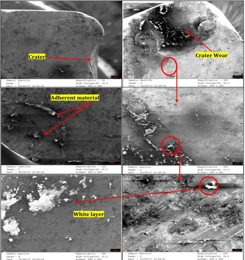
Adherent Chip
Adherent material VB max Adherent material
Adherent material
White layer
Crater Crater Wear
Fig. 12. SEM images of Flank and Crater wear and rake face of the cutting inserts.
Adherent layers of machined material occur at low and medium cutting speed, however flank wear and notch wear occur on the cutting tools because of the higher level of heat generated when used at higher cutting speeds.
We noted also the presence of micros welding and chip adhesion on the rake and flank face for the reduced cutting speeds (Figs. 9 and 11), while this phenomenon has been exceeded with the high speed ranges where the zone and contact time at the tool-chip interface were
reduced, which reduces the possibility of adhesion of micro-chips detached from the workpiece to the cutting edge of the tool during the cutting process. Nose degradation and fractures were also observed on the rake face of the cutting tools, while adhesive wear, micro cracks of coating layer, plastic deformation and notch wear were observed on the flank face (clearance face) and cutting tool nose.
the rake face. This white layer is in direct relation to the diffusion phenomenon at the tool interface and would act as an element which attenuates the wear of the tool.
This white layer does not consist of carbide or an oxide, but rather it is a ferrite alloyed mainly to chromium, formed due to the diffusion of chromium, ferrite and carbon from the workpiece to the cutting tool, those elements diffused are adhered to the rake face forming white layers which contribute the diminution of wear evolution.
4. CONCLUSION
In order to optimize dry machining of SAE 1030 steel, it was necessary to identify the wear patterns, determine the contact conditions which lead to wear mechanisms and know the relationship between the contact parameters and the machining conditions.
The idea was to choose the adequate and optimal cutting conditions that limit the triggering or aggravation of adhesion phenomena.
It has been conclude that the most influential element on the temperature and wear of cutting tools is the cutting speed, followed by the feed rate and finally the depth of cut.
The cutting speed associated with the tool and machined material control the service life of a cutting tool.
Coatings have an important role in improving the lifetime of carbides, but they do not possess great power in terms of thermal protection.
Crater wear is highly influenced by both cutting speed and feed rate, despite the fact that flank wear is mainly affected by cutting speed and contact conditions; this is related to the wear mechanisms such as diffusion and adhesion.
On the rake face, the main wear mechanisms are the adhesion and the diffusion, essentially activated by cutting speed temperature, which lead to Nose degradation.
It has been found that the best tool life was registered by KC810 inserts (288 min); while the
lower service time was registered by KC910 Inserts (35 min). The optimal cutting parameters for machining SAE 1030 Carbon steel were
VC=250 m/min, f=0.11 mm/rev and a=1 mm, while the most unfavorable conditions were
VC=250 m/min, f=0.11 mm/rev and a=1.5 mm.
It is important to note that it has been found that inserts with multilayer TiN coating are more suitable for the machining of SAE 1030 carbon steel due to their wear resistance.
REFERENCES
[1] J. Rech, Influence of cutting tool coatings on the tribological phenomena at the tool–chip interface in orthogonal dry turning, Surface and Coatings Technology, vol. 200, iss. 16-17, pp. 5132 – 5139, 2006, doi:
10.1016/j.surfcoat.2005.05.032
[2] A.P. Kene, K. Orra, S.K. Choudhury, Experimental Investigation of tool Wear Behavior of Multi-Layered Coated Carbide Inserts Using Various Sensors in Hard Turning Process, IFAC-Papers on Line, vol. 49, iss. 12, pp. 180-184, 2016, doi:
10.1016/j.ifacol.2016.07.592
[3] G.D.S. Galoppi, M.S. Filho, G.F. Batalha, Hard Turning of Tempered DIN 100Cr6 Steel with Coated and no Coated CBN Inserts, Journal of Materials Processing Technology, vol. 179, iss. 1-3, pp. 146– 153, 2006,doi: 10.1016/j.jmatprotec.2006.03.067 [4] M. Nalbant, H. Gökkaya, I. Toktaş, G. Sur, The
experimental investigation of the effects of uncoated, PVD- and CVD-coated cemented carbide inserts and cutting parameters on surface roughness in CNC turning and its prediction using
artificial neural networks, Robotics and
Computer-Integrated Manufacturing, vol. 25, iss. 1, pp. 211–223, 2009, doi:
10.1016/j.rcim.2007.11.004
[5] S.R. Carvalho, S.M.M. Lima e Silva, A.R. Machado G. Guimarães, Temperature determination at the chip–tool interface using an inverse thermal model considering the tool and tool holder. Journal of Materials Processing Technology, vol. 179, iss. 1-3, pp. 97–104, 2006, doi:
10.1016/j.jmatprotec.2006.03.086
[6] J.Rech, J-L. Battaglia, A. Moisan, Influence tribologique des revêtements pour
outils-coupants, in 16ème Congrès Français de
Mécanique, 1-5 Septembre, 2003, CFM 2003, Nice, France, pp. 1-6.
l’alliage de titane aéronautique Ti–6Al–4V,
Comptes Rendus Mécanique, vol. 336, iss. 10,
pp. 772–781, 2008, doi :
10.1016/j.crme.2008.07.007
[8] M. Benghersallah, L. Boulanouar, Mahfoudi, S. Dominiak, Examen morphologique de l’usure des plaquettes carbure métallique en fraisage, in Conférence Internationale sur la Productique, 03-04 November, 2007, C.I.P. 2007, Sétif, Algérie, pp. 1-6.
[9] J. Rec, A. Kusiak, J.L. Battaglia, Tribological and thermal functions of cutting tool coatings, Surface and Coatings Technology, vol. 186, iss. 3, pp. 364–371, 2004, doi:
10.1016/j.surfcoat.2003.11.027
[10] N. Senthil Kumar, T. Tamizharasan, Impact of Interface Temperature over Flank Wear in Hard
Turning Using Carbide Inserts, Procedia
Engineering, vol. 38, pp. 613–621, 2012, doi:
10.1016/j.proeng.2012.06.076
[11] S. Chinchanikar, S.K. Choudhury, Evaluation of Chip-tool Interface Temperature: Effect of Tool Coating and Cutting Parameters during Turning Hardened AISI 4340 Steel, Procedia Materials Science, vol. 6, pp. 996-1005, 2014, doi:
10.1016/j.mspro.2014.07.170
[12] S. Hernandez, J. Hardell, H. Winkelmann, M. Rodriguez Ripoll, B. Prakash, Influence of temperature on abrasive wear of boron steel and hot forming tool steels, Wear, vol. 338-339, pp. 27-35, 2015, doi:
10.1016/j.wear.2015.05.010
[13] Y. Liu, J.Deng, F. Wu, R Duan, X. Zhang, Y. Hou,
Wear resistance of carbide tools with textured flank-face in dry cutting of green alumina
ceramics, Wear, vol. 372-373, pp. 91-103, 2017,
doi: 10.1016/j.wear.2016.12.001
[14] M. Kamruzzaman, N.R. Dhar, Effect of High– Pressure Coolant on Temperature, Chip, Force, Tool Wear, Tool Life and Surface Roughness in Turning AISI 1060 Steel, G.U. Journal of Science, vol. 22, no. 4, pp. 359–370, 2009.
[15] P.C. Wanigarathne A.D. Kardekar, O.W. Dillon, G. Poulachon, I.S. Jawahir, Progressive tool-wear in machining with coated grooved tools and its correlation with cutting temperature, Wear, vol. 259, iss. 7-12, pp. 1215–1224, 2005, doi:
10.1016/j.wear.2005.01.046
[16] O. Hatt, P. Crawforth, M. Jackson, On the mechanism of tool crater wear during titanium alloy machining, Wear, vol. 374-375, pp. 15-20, 2017, doi:
10.1016/j.wear.2016.12.036
[17] H. Buse, P. Feinle, Model System Studies of Wear Mechanisms of Hard Metal Tools when Cutting CFRP, Procedia Engineering, vol. 149, pp. 24-32, 2016,
doi: 10.1016/j.proeng.2016.06.634
[18] K.C. Ee, A.K. Balaji, I.S. Jawahir, Progressive tool-wear mechanisms and their effects on
chip-curl/chip-form in machining with
grooved tools: an extended application of the equivalent tool face (ET) model, Wear, vol. 255, no. 7-12, pp. 1404–1413, 2003, doi:
10.1016/S0043-1648(03)00112-1
[19] S. Tooptong, K.H. Park, S.W. Lee, P.Y. Kwon, A Preliminary Machinability Study of Flake and Compacted Graphite Irons with Multilayer Coated
and Uncoated Carbide Inserts, Procedia
Manufacturing, vol. 5, pp. 644–657, 2016, doi:
10.1016/j.promfg.2016.08.053
[20] A. Benamar, G. Inglebert, M. Boumahrat, Durée de vie d’un carbure P20 pour le chariotage d’un acier XC38 à rugosité contrôlée, Mécanique & Industries, vol. 6, no. 6, pp. 635–640, 2006, doi:
10.1051/meca:2006009
[21] Y. Huang, T.G. Dawson, Tool crater wear depth modeling in CBN hard turning, Wear, vol. 258, no. 9, pp. 1455–1461, 2005, doi:
10.1016/j.wear.2004.08.010
[22] R.T. Coelho, Eu-Gene Ng, M.A. Elbe, Tool wear when turning hardened AISI 4340 with coated PCBN tools using finishing cutting conditions; International Journal of Machine Tools and Manufacture, vol. 47, no. 2, pp. 263–272, 2007,
doi: 10.1016/j.ijmachtools.2006.03.020
[23] R.F.Brito S.R. Carvalho, S.M.M Lima e Silva, J.R. Ferreira, Thermal analysis in coated cutting tools, International Communications in Heat and Mass Transfer, vol. 36, iss. 4, pp. 314–321, 2009,
doi: 10.1016/j.icheatmasstransfer.2009.01.009
[24] Chetan, B.C. Behera, S. Ghosh, P.V. Rao, Wear behavior of PVD TiN coated carbide inserts during machining of Nimonic 90 and Ti6Al4V super alloys
under dry and MQL conditions, Ceramics
International, vol. 42, iss. 13, pp. 14873-4885, 2016,
doi: 10.1016/j.ceramint.2016.06.124
[25] I. Shyha, S. Gariani, M. Bhatti, Investigation of Cutting Tools and Working Conditions Effects when Cutting Ti-6al-4V using Vegetable Oil-Based Cutting Fluids, Procedia Engineering, vol. 132, pp. 577-584, 2015, doi:
10.1016/j.proeng.2015.12.535
[26] G.H. Lim, Tool-wear monitoring in machine
turning, Journal of Materials Processing
Technology, vol. 51, iss. 1-4, pp. 25-36, 1995,
doi: 10.1016/0924-0136(94)01354-4
[27] T. Selvaraj, C. Balasubramani, S. Hari Vignesh M.P. Prabakaran, Tool Wear Monitoring By
Image Processing, International Journal of
[28] H. Çalışkan, M. Küçükköse, The effect of aCN/TiAlN coating on tool wear, cutting force, surface finish and chip morphology in face milling of Ti6Al4V superalloy, International Journal of Refractory Metals and Hard Materials, vol. 50, pp. 304–312, 2015, doi:
10.1016/j.ijrmhm.2015.02.012
[29] X. Chen, J. Xu, Q. Xiao, Cutting performance and wear characteristics of Ti(C,N)-based cermet tool in machining hardened steel, International Journal of Refractory Metals and Hard Materials, vol. 52, pp. 143–150, 2015, doi:
10.1016/j.ijrmhm.2015.06.006
[30] T. Yang, Lei Ni, Q. Zheng, J. Xiong, Cutting wear, microstructure and mechanical properties of (Ti0.5,W0.5)C-15 based cermet inserts containing Mo2C, International Journal of Refractory Metals and Hard Materials, vol. 68, pp. 151-158, 2017,
doi: 10.1016/j.ijrmhm.2017.07.011
[31] F. Gong, J. Zhao, Y. Jiang, H. Tao, Z. Li, J. Zang,
Fatigue failure of coated carbide tool and its influence on cutting performance in face milling SKD11 hardened steel, International Journal of Refractory Metals and Hard Materials, vol. 64, pp. 27-34, 2017, doi:
10.1016/j.ijrmhm.2017.01.001
[32] G.K. Dosbaeva, M.A. El Hakim, M.A. Shalaby, J.E. Krzanowski, S.C. Veldhuis, Cutting temperature
effect on PCBN and CVD coated carbide tools in hard turning of D2 tool steel, International Journal of Refractory Metals and Hard Materials, vol. 50, pp. 1-8, 2015, doi:
10.1016/j.ijrmhm.2014.11.001
[33] Y. Sahin, Comparison of tool life between ceramic and cubic boron nitride (CBN) cutting
tools when machining hardened steels, Journal
of materials processing technology, vol. 209, iss. 7, pp. 3478–3489, 2009, doi:
10.1016/j.jmatprotec.2008.08.016
[34] D. Sudhakara, G. Prasanthi, Application of Taguchi Method for Determining Optimum Surface Roughness in Wire Electric Discharge Machining of P/M Cold Worked Tool Steel (Vanadis-4E), Procedia Engineering, vol. 97, pp. 1565–1576, 2014, doi:
10.1016/j.proeng.2014.12.440
[35] Kennametal grade descriptions, available at:
https://cets.com/resources/kennametal-grades,
accessed: 29.06.2017.
[36] E. Usui, Advancement of Intelligent Production, pp. 419-425, Elsevier Science, 1994.
[37] X. Cui, J. Guo, Effects of cutting parameters on tool temperatures in intermittent turning with the formation of serrated chip
considered, Applied Thermal Engineering,
vol. 110, pp. 1220–1229, 2017, doi: