The Cooling Design of a High-Speed Rotating Axis with
Ribbed Turbulators
Sheng-Chung Tzeng*, Tzer-Ming Jeng , Yen-Chan Wang
Department of Mechanical Engineering, Chienkuo Technology University, Taiwan, ROC
Received 20 October 2012; received in revised form 23 September 2012; accepted 15 December 2012
Abstract
This work experimentally and numerically investigated the heat transfer characteristics of the high-speed
rotating axis of five-axis processing machines. The test section of rotation axis possesses the novel design with ribbed
turbulators to strengthen heat dissipation. A good cooling design will reduce the coefficient of thermal expansion, the
thermal deformation and the damage of cutting tools to enhance the delicacy and the efficiency of the processing
machining. In order to make the analysis meaningful, the experimental condition was made as close to the working of
the real high-speed rotation axis as possible, and the oil was employed as the coolant. The relevant experiments
analyzed the heat transfer distributions in radial directions and the axial directions of the rotor located in the test
section of round cylinder with different rotational speeds. The empirical formula based on the test results was
proposed to provide critical references for machining delicacy improvement in five-axis processing machines.
Keywords: heat transfer, high-speed rotation, five-axis processing machine, ribbed turbulators
1.
Introduction
The technical research and development of modern machine tools advance at a tremendous pace. The demand of machine
tools has changed from traditional lathes and milling machines to tool machines for special purposes, such as high-speed
five-axis processing machines. To meet the growing demand, the following development of various kinds of high-speed
five-axis processing machines is growing mature. Nowadays, the drive of the main shaft of a regular high-speed five-axis
processing machine is about 6~9kW and its rotational speed of the main shaft is about 5,000~50,000rpm. Since the workpiece
of high-speed five-axis processing machines is a complicated 3D district, the accurate degree in processing is relatively high as
well. A regular work piece of complicated geometry needs to relay on a high speed of five-axis processing machines. As for
increasing the accuracy, the key factors are to decrease the damage of cutting tools and to improve the cooling and lubricating
of high-speed rotational shafts.
Researches in the rotating axis of the general fluid recently, Song et al. [1] experimentally measure the heat transfer
performance of axial rotating heat pipes at rotational speeds up to 4000rpm. A cylindrical and an internally tapered heat pipe
with water as the working fluid were tested with different fluid loadings that ranged from 5% to 30% of the total interior volume.
Bouafia et al [2] proposed the experimental results of convective heat transfer in an annular gap flow, between a heated rotating
inner cylinder and a cooled stationary outer cylinder with or without axial flow. This study results for rotational flow without
*Corresponding author. E-mail address: [email protected]
axial flow reveal the interest of the presence of grooves and an important heat transfer as the velocity increase. In presence of
axial flow, their investigations conducted in turbulent flow show that the situation of a smooth air gap is more favorable for heat
transfer at the rotor. Hwang and Lai [3] indicated the three-dimensional mixed convection for a constant-property laminar fluid
flow through a periodical two-pass square channel with radial rotation is presented. Kolyshkin and Vaillancourt [4] studied
linear stability of Couette flow with rotating inner cylinder and radially nonuniform internal heat sources. Yan and Soong [5]
developed mixed convection in radially rotating rectangular ducts. Soong and Yan [6] investigated the development of
secondary flow and convective heat transfer in isothermal/iso-flux rectangular ducts rotating about a parallel axis. Soong et al.
[7] presented the experimental work on the qualitative nature of three-dimensional flow structure between two rotating co-axial
disks at a relatively wide range of rotational conditions. They revealed distinct flow structure between two disks rotating at
various conditions and provided profound insights for better understanding of fundamental mechanisms of the complex
three-dimensional rotating flows that are valuable in analysis and design of rotating flow systems.
This study is mainly discussing about the coefficient of the high-speed rotation axis of five-axis processing machines, and
will focus on researches about rotating axis with ribbed turbulators to provide design reference for high-speed rotating spindles.
The experiment is targeted at the actual geometric dimension and operating parameter of the rotating axis of the five-axis
machine and taking the relevant physical parameters of the most advanced high-speed five-axis machining tool as references.
The current design of rotating axis can lead to high temperature in some regions, and this may cause the delicacy of machining
not good enough. If the contact area of heat convection of cooling lubricant could be increased, adding the spoiler ribs can
improve the unevenness of temperature distribution and the thermal expansion produced in rotating high-speed axis. The
limitation of high flow resistance can also be overcome and the efficiency of heat convection can be increased dramatically.
This technology can reduce the coefficient of thermal expansion and improve the delicacy of machining. Those improvements
will bring significant economic benefits for the precision processing industry. For instance, the yield of processing can be better,
the cost of processing can be lower, and the operating time of this kind of advanced machining equipment can be longer.
2.
Experiments and Methodology
2.1. Experimental Equipments and Test Section
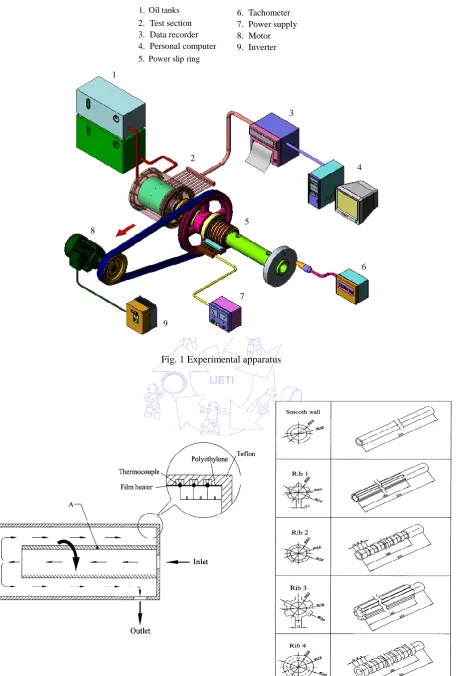
All experimental equipment, shown in Fig. 1, can be divided into five parts: experimental test section, thermocouples,
rotating spindle, oil cooling system, and data acquisition system. Descriptions for the main experimental devices are as followed:
the experimental test section is made up of the smooth wall and four different ribbed walls. There were 19 temperature
measurement points placed in the inner wall shell of the experimental test section. The main power source of the experimental
rotating spindle is high-speed AC motor and it also equipped with an inverter to control the rotational speed to simulate the
practical rotation of axis.
The various rotational speeds in this experiment are 0, 500, 750, 1000, 1250, 1500, 1750, 2000, 2250, and 2500. The
cooling oil is used as the high quality cooling lubricant. The oil cooling system uses two sets of storage tanks. One is for forcing
the cooling oil to be transported to the interior of the test section and there are four kinds of flow rates: 2.083cm3/s,
5.279cm3/s, 6.994cm3/s, and 9.635cm3/s. The other is for oil returning. The temperature measurement of the test section is to measure the signals of measure points by TT-T-30SLE high precision thermocouples. Measured signals will be transferred to
1. Tank 2. Test section 3. Data recorder 4. Personal computer 5. Sip ring for input
power
6. Tachometer 7. Power supply 8. Motor 9. Inverter
1
8
9
9
7 5
6 4 3
2 5. Power slip ring 1. Oil tanks
Fig. 1 Experimental apparatus
The test section can be divided into the internal rotating axis and the external stationary cylinder. The basic material for
the external cylinder is Telfon and to heat by a DC power supply and power slip ring. The heating area is a 0.012m2 stainless
steel of high resistance heating film (the resistance is 30.7ohms) using the glue with excellent thermal conductivity as adhesives
to fix the heating film on the heating section. To respectively measure the local heat transfer distribution in axial and side wall,
nineteen measure points were buried evenly in the axial direction to output the temperature data. The diameter of the internal
rotating cylinder is 0.0174m. The diameter of the external stationary cylinder is 0.05m. Test section is shown in Fig. 2 in this
study.
2.2.Data Reduction
All the measured data could be reduced to be the following relevant dimensionless parameters.
VDo
Re (1)
V D Ro o
(2)
2 3
L g Gr
(3)
Nu=
oil b w
o loss in oil o
k ) T T ( A
D ) Q Q ( k / hD
(4)
The method of estimating the heat loss is to close the outlet of the pipeline of the test section so that no outer fluid would
get in the channel. Then, heat the test section with electric current. Since there is no outside air flow and heat exchange with
those in the pipe, it is pure natural convection in the pipeline. The energy balance equation can be expresses as followed:
I V
Qin (5)
w b
loss
in Q hA
-Q (6)
Without air flowed into the test section and the wall temperature already remained stable, the natural convection
w b
hA - equals to zero because the temperature of the air of natural flow is the same as the wall temperature. After the heat
input from the film heater will be borne by the external environment and the test section for heat exchange. The equation can be
expresses as followed:
w b
n loss
in Q C T
-Q (the value of n is between 1~19) (7)
When we estimated the heat loss, we entered 0.15W~7.75W into the test section and we recorded the wall temperature
and the temperature of the external environment when the temperature of the test section reached stable under different heating.
We took the advantage of the relationship of the temperature difference between wall temperature and the temperature of the
external environment to find the equation of estimating the heat loss. According to the equation of estimating the heat loss, the
result of every temperature measuring point is a straight line passing the origin. The method used is Root Mean Square Method
and all possible errors are within 7%.
2.3. Uncertainity Analysis
the readout of data recorder. The difference between wall temperature and bulk temperature is greater than 62℃. The rotational
speed was detected by a tachometer with a bit of oscillation. Notably, the maximum error of the rotational speed was 2﹪at
2500rpm. The analysis included uncertainties of oil thermophysical properties. Uncertainties in parameters were estimated by
using the root-sum-square method of Kline and McClintock [8]. The measured value and its uncertainty can be expressed as
R R R. The uncertainties of Re, Ro, Re, Gr, Gr, and Nu were estimated within 2.5﹪, 2.2﹪, 2.6﹪, 5.1﹪,
5.4
﹪and 6.23﹪, respectively.
2.4. Mathematical Equations and Numerical Procedure
In order to simplify the present problem, some assumptions were made as follows: (1) the fluid flow is in the steady state,
laminar and incompressible; (2) the properties of the fluid are constant, and (3) the flow field is axial symmetric (i.e. /=0).
The following dimensionless groups are introduced to facilitate the dimensionless transformation of these equations.
r
R ,
z
Z ,
i r r r u U , i r u
U ,
i z z r u U , ri
Re , Pr , o i o T T T T (8)
Besides, the stream function () and vorticity () are introduced.
Z R
Ur
1 ,
R R
Uz
1 ,
Z U R
Uz r
(9)
Then the dimensionless governing equations can be obtained as follows.
2 2 2 2 Z R
(10)
} )] ( 1 [ { Re 1 2 ) ( ) ( 2 2 Z R R R R Z U R U Z U R
Ur z
(11)
] ) ( 1 [ Re 1 2 2 2 R U Z U R U R R R R U U Z U U R U
Ur z r
(12) ] ) ( 1 [ Pr Re 1 ) ( 2 2 Z R R R R Z U R
Ur z
(13)
Boundary conditions [9] are as follows.
0 Z U
, 2
2 1 Z R
at Z=0 and Z=L/ri (14)
1
U ,0,
R R R 1
at R=ri/ (15)
0
U ,
R R R 1
at R=ro/ (16)
The governing equations were discretized according to the power-law scheme proposed by Patankar [10]. All discretized
algebraic equations were solved by using the SIS (Strong Implicit Solver) algorithm developed by Lee [11]. The velocity
components Ur and Uz were determined from the stream function. When the velocity components had been determined, the
energy equation was solved to yield the temperature distribution. The solutions were verified by varying the grid spacing and the
convergence criterion. A high density grid node was used near the walls to predict the flow fields accurately. The number of
grid-cells in the flow direction was 1001, and that perpendicular to the flow was 61. The convergence criterion is
( )
5min ) ( max ) 1 ( ) ( 10 1 /
n n n
n
F F F
F
3.
Results and Discussion
Fig. 3 shows the relationships of the test modules and the wall temperatures at
q
in= 0.18W/cm2. The result illustrated thatwhen the rotating axis stops, that is when Ro0, both ends of the wall temperature showed a downward trend because the
effect of import and export. The two ends of the outlets of the pipeline are the closest to the external environment, so they are
most affected by the external environment and heat will be dissipated to both sides of the pipeline, leading lower temperature at
both ends.
Fig. 3 Local temperature distributions for various test sections at different Reynolds numbers
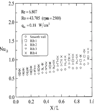
Fig. 4 shows the heat transfer efficiency when q0.18 W cm/ 2 and Re=6.807 and Ro=43.705. Generally speaking, the
heat convection in Rib 4 is the best. In addition, the outlet has upwards trend caused by the export effect at the rotating
condition.
When the forced convective parameter Re=1.472, 4.048 and 6.807, we compared the heat transfer efficiency of rotating
axis between five test modules as shown in Fig. 5. The general performance of Rib 4 is the best. When the rotation number
increases, the heat transfer efficiency increases. Usually the higher the heat convection passes through, the better the buoyancy
is. It means that when the machining tool’s axis rotates in high speed and generates high temperature and high buoyancy of the
tribological oil will increase the heat convection efficiency. Fig. 6 indicates that the higher rotation number resulted in a higher
heat transfer enhancement by comparing with those at stationary condition, especially for Rib 4.
Fig. 5 Average Nusselt number as a function of Rotation number
Fig. 6 Heat transfer enhancement of rotation for various Ro at Re4.048and qin 0.18 W cm/ 2
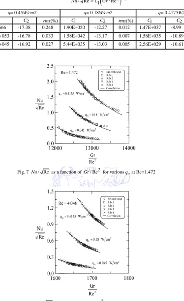
Table 1 The empirical formula of Nu in terms of Re and Gr
Re
2
2/ Re 1 / Re C
Nu C Gr
q= 0.45W/cm2 q= 0.18W/cm2 q= 0.4175W/cm2
1
C C2 rms(%) C1 C2 rms(%) C1 C2 rms(%)
1.472 162.666 -17.38 0.248 1.90E+050 -12.27 0.012 1.47E+037 -8.99 0.001
4.048 1.61E+053 -16.78 0.033 1.58E+042 -13.17 0.007 1.56E+035 -10.89 0.002
6.807 7.98E+045 -16.92 0.027 5.44E+035 -13.03 0.005 2.56E+029 -10.61 0.001
Fig. 7 Nu/ Re as a function of Gr/ Re2 for various qin at Re=1.472
Fig. 9 Nu/ Re as a function of Gr/ Re2 for various qin at Re=6.807
0 2 4 6 8 10 12 14 16
Z
8 10 12 14 16 18 20 22 24
R
Ta=6583, Pr=0.7
0 2 4 6 8 10 12 14 16
Z
8 10 12 14 16 18 20 22 24
R
Ta=1009146, Pr=0.7
0 2 4 6 8 10 12 14 16
Z
8 10 12 14 16 18 20 22 24
R
Ta=2916431, Pr=0.7
Fig. 10 Streamlines for Taylor-Couette Flow in Mode A (with smooth wall)
0 2 4 6 8 10 12 14 16
Z
8 10 12 14 16 18 20 22 24
R
Ta=6583, Pr=0.7
0 2 4 6 8 10 12 14 16
Z
8 10 12 14 16 18 20 22 24
R
Ta=1009146, Pr=0.7
0 2 4 6 8 10 12 14 16
Z
8 10 12 14 16 18 20 22 24
R
Ta=2916431, Pr=0.7
International Journal of Engineering and Technology Innovation, vol. 3, no. 1, 2013, pp. 38-48 47
0
2
4
6
8
10
12
14
16
Z
8
10
12
14
16
18
20
22
0.07 0.13 0.20 0.27 0.33 0.40 0.47 0.53 0.60 0.67 0.73 0.80 0.87 0.93
R
Ta=6583, Pr=0.7
0
2
4
6
8
10
12
14
16
Z
8
10
12
14
16
18
20
22
24
R
Ta=6583, Pr=0.7
0
2
4
6
8
10
12
14
16
Z
8
10
12
14
16
18
20
22
24
R
Ta=1009146, Pr=0.7
0
2
4
6
8
10
12
14
16
Z
8
10
12
14
16
18
20
22
24
R
Ta=2916431, Pr=0.7
Fig. 12 Isothermal Lines for Taylor-Couette Flow in Mode A (with smooth wall)
0
2
4
6
8
10
12
14
16
Z
8
10
12
14
16
18
20
22
24
0.07 0.13 0.20 0.27 0.33 0.40 0.47 0.53 0.60 0.67 0.73 0.80 0.87 0.93
R
Ta=6583, Pr=0.7
0
2
4
6
8
10
12
14
16
Z
8
10
12
14
16
18
20
22
24
R
Ta=6583, Pr=0.7
Ribs
0
2
4
6
8
10
12
14
16
Z
8
10
12
14
16
18
20
22
24
R
Ta=1009146, Pr=0.7
Ribs
0
2
4
6
8
10
12
14
16
Z
8
10
12
14
16
18
20
22
24
R
Ta=2916431, Pr=0.7
Ribs
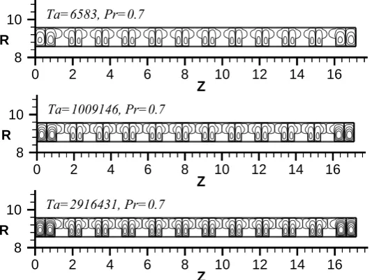
Fig. 10 shows the streamlines in Mode A (with smooth wall). The results depicts that the vortices began to occur at the
two end sides of the annular channel as Ta=6583. When Taylor number equals 1009146, 7 pairs of vortices clearly appeared.
The vortices became 10 pairs as Taylor number increased to be 2916431. The present numerical model seems to successfully
predict Taylor vortices. However, the assumption of steady-state flow might reduce some flow perturbations, resulting in an
over-predicted critical Taylor number (Theoretical critical Ta=1708). Fig. 11 displays the streamlines in Mode B (with ribbed
wall). As shown, a complete pair of vortex could be found between adjacent ribs, but the vortices did not obviously occur at the
space over the ribs. It may be also attributed to the assumption of steady-state flow. Fig. 12 and 13 depict the isothermal lines in
Mode A (with smooth wall) and in Mode B (with ribbed wall), respectively. As shown in Mode A (with smooth wall), the
temperature gradient near wall became sharp when Taylor number increased. However, in Mode B (with ribbed wall), the
contours of temperature had little change with various Taylor numbers. It might be because of effective Taylor number and
needed further study.
4.
Conclusions
According to the tests above, the conclusions can be drawn as the followings:
(1) When the rotating axis stay still, both ends of the wall temperature showed a downward trend.
(2) At rotating condition, the heat convection in Rib 4 is the best. In addition, the outlet has upwards trend caused by the export effect at the rotating condition.
(3) The higher rotation number resulted in a higher heat transfer enhancement by comparing with those at stationary condition, especially for Rib 4.
(4) The empirical formula of Nu in terms of Re and Gr, based on the test results, was proposed .
Acknowledgements
The authors would like to thank the National Science Council of the Republic of China for financially supporting this
research under Contract No. NSC-100-2221-E-270-014-MY3.
References
[1] Song F., Ewing D. and Ching C. Y., “Experimental investigation on the heat transfer characteristics of axial rotating heat pipes,” Int. J. Heat Mass Transfer, vol. 47, pp.4721-4731, 2004.
[2] Bouafia, M., Bertin, Y., Saulnier, J. B. and Ropert, P., “Experimental analysis of heat transfer in a narrow and grooved annular gap with rotating inner cylinder,” Int. J. Heat Mass Transfer, vol. 41, pp. 1279-1291, 1998.
[3] Hwang, J. J. and Lai, D. Y., “Three-dimensional mixed convection in a rotating multiple-pass square channel,” Int. J. Heat Mass Transfer, vol. 41, pp. 979-991, 1998.
[4] Kolyshkin, A. A. and Vaillancourt, Rémi., “Linear stability of Couette flow with rotating inner cylinder and radially nonuniform internal heat sources,” Int. J. Heat Mass Transfer, vol. 39, pp. 537-545, 1998.
[5] Yan, W. M. and Soong, C. Y., “Simultaneously developing mixed convection in radially rotating rectangular ducts,” Int. J. Heat Mass Transfer, vol. 38, pp. 665-677, 1995.
[6] Soong, C. Y. and Yan, W. M., “Development of secondary flow and convective heat transfer in isothermal/iso-flux rectangular ducts rotating about a parallel axis, Int. J. Heat Mass Transfer, vol. 42 pp. 497-510, 1999.
[7] Soong, C. Y., Wu, C. C., Liu, T. P. and Liu, T. P., “Flow structure between two co-axial disks rotating independently,” Experimental Thermal and Fluid Science, vol. 27, pp. 295-311, 2003.

![Pour un étiquetage automatique des séquences verbales figées : état de l’art et approche transformationnelle (For An Automatic Fixed Verbal Sequence Tagging: State Of Art And Transformational Approach) [in French]](data:image/gif;base64,R0lGODlhAQABAIAAAP///wAAACH5BAEAAAAALAAAAAABAAEAAAICRAEAOw==)