Adv. Radio Sci., 5, 407–412, 2007 www.adv-radio-sci.net/5/407/2007/ © Author(s) 2007. This work is licensed under a Creative Commons License.
Advances in
Radio Science
LOFAR in Germany
W. Reich
Max-Planck-Institut f¨ur Radioastronomie, Auf dem H¨ugel 69, 53121 Bonn, Germany
Abstract. The LOw Frequency ARray – LOFAR – is a new fully digital radio telescope designed for frequencies be-tween 30 MHz and 240 MHz centered in the Netherlands. In May 2006 ten German institutes formed the German LOng Wavelength consortium – GLOW – to coordinate its contri-butions and scientific interests to the LOFAR project. The first LOFAR station CS1 was installed in summer 2006 near Exloo/Netherlands. The second station IS-G1 is presently been placed in the immediate vicinity of the Effelsberg 100-m radio telescope near Bad M¨unstereifel/Ger100-many. This con-tribution briefly describes the basic properties and aims of LOFAR, the aims of the GLOW consortium and the actual activities to install a LOFAR station at the Effelsberg site.
1 Introduction and background
Radio emission covers the longest wavelength range of the electromagnetic spectrum, where emission from space is been observed. This means low angular resolution even for large telescopes when compared with optical, infrared or X-ray telescopes. Classical single-dish radio telescopes like the Effelsberg 100-m dish have a huge collecting area and high sensitivity, however, at 3 cm (10 GHz) its angular resolu-tion is about 1’, which is not always sufficient for detailed studies. Higher angular resolution is achieved by synthesis telescopes like the Very Large Array (VLA) or the West-erbork Synthesis Radio Telescope (WSRT), where a num-ber of small telescopes are distributed over distances of a few kilometres. The signals received by each element are combined into images of arcsecond angular resolution. Very Long Baseline Interferometry (VLBI) uses telescopes with distances up to the Earth diameter or even antennas in space, where the raw signals need to be stored on tapes or disks Correspondence to: W. Reich
and are being correlated off-line. That way radio astronomy becomes a record holder in angular resolution for any astro-nomical observation by producing images showing milli arc-second structures. For all these observations classical radio telescopes as sketched in Fig. 1 are used, where a paraboloid dish is pointed towards the object under investigation and the receivers being installed in the telescopes focus to record its emission. At low frequencies, however, a different technol-ogy can be used (as sketched in Fig. 1), where the signals from numerous elements are electronically delayed in such a way that the waves from a certain direction are received in phase. This technology is presently limited to the long wave-length range. LOFAR is based on this concept of beam for-mation and utilizes actual digital components to allow obser-vations of unprecedented flexibility over a wide continuous wavelength range.
2 The LOFAR concept and basic parameters
The ideas and the concept of LOFAR were developed at AS-TRON (Dwingeloo/Netherlands, see Bregmann, 2000). FAR is actually realized by ASTRON on behalf of the LO-FAR Foundation, which includes a number of Universities and Research Institutes. However, LOFAR is more than a new radio telescope for observations in the long wavelength range with unprecedented sensitivity and angular resolution. Its basic concept is that of a sensor network with high-speed data links, which allows to connect any kind of sensors for non-astronomical applications as well. For more details see: www.lofar.org or www.lofar.de (in German). A brief descrip-tion including the actual status of the LOFAR project was given by Falcke et al. (2006).
The antenna elements of LOFAR are inverted-V crossed dipole antennas for two orthogonal directions (NE-SW and SE-NW) allowing to simultaneously observe all Stokes pa-rameters. The dipoles have a field of view close to the entire
408 W. Reich: LOFAR in Germany with version 1.1 of the LATEX class copernicus.cls.
Date: 16 January 2007
LOFAR in Germany
W. Reich
Max-Planck-Institut f¨ur Radioastronomie, Auf dem H¨ugel 69, 53121 Bonn, Germany, [email protected]
Abstract. The LOw Frequency ARray - LOFAR - is a new fully digital radio telescope designed for frequencies be-tween 30 MHz and 240 MHz centered in the Netherlands. In May 2006 ten German institutes formed the German LOng Wavelength consortium - GLOW - to coordinate its contri-butions and scientific interests to the LOFAR project. The first LOFAR station CS1 was installed in summer 2006 near Exloo/Netherlands. The second station IS-G1 is presently been placed in the immediate vicinity of the Effelsberg 100-m radio telescope near Bad M¨unstereifel/Ger100-many. This con-tribution briefly describes the basic properties and aims of LOFAR, the aims of the GLOW consortium and the actual activities to install a LOFAR station at the Effelsberg site.
1 Introduction and background
Radio emission covers the longest wavelength range of the electromagnetic spectrum, where emission from space is been observed. This means low angular resolution even for large telescopes when compared with optical, infrared or X-ray telescopes. Classical single-dish radio telescopes like the Effelsberg 100-m dish have a huge collecting area and high sensitivity, however, at 3 cm (10 GHz) its angular resolu-tion is about 1’, which is not always sufficient for detailed studies. Higher angular resolution is achieved by synthesis telescopes like the Very Large Array (VLA) or the West-erbork Synthesis Radio Telescope (WSRT), where a num-ber of small telescopes are distributed over distances of a few kilometres. The signals received by each element are combined into images of arcsecond angular resolution. Very Long Baseline Interferometry (VLBI) uses telescopes with distances up to the Earth diameter or even antennas in space, where the raw signals need to be stored on tapes or disks and are being correlated off-line. That way radio astronomy
Correspondence to:[email protected]
Fig. 1.The pointing of a multi-element telescope like LOFAR in a certain direction is done by delaying the received signals from each element in such a way that the wavefront from a certain direction is received in phase. Classical telescopes are pointed mechanically.
becomes a record holder in angular resolution for any astro-nomical observation by producing images showing milli arc-second structures. For all these observations classical radio telescopes as sketched in Fig. 1 are used, where a paraboloid dish is pointed towards the object under investigation and the receivers being installed in the telescopes focus to record its emission. At low frequencies, however, a different technol-ogy can be used (as sketched in Fig. 1), where the signals from numerous elements are electronically delayed in such a way that the waves from a certain direction are received in phase. This technology is presently limited to the long wave-length range. LOFAR is based on this concept of beam for-mation and utilizes actual digital components to allow obser-vations of unprecedented flexibility over a wide continuous wavelength range.
Fig. 1. The pointing of a multi-element telescope like LOFAR in a certain direction is done by delaying the received signals from each element in such a way that the wavefront from a certain direction is received in phase. Classical telescopes are pointed mechanically.
2 W. Reich: LOFAR in Germany
Fig. 2. LOFAR allows to form several beams. Within the beam of a single antenna element, which defines LOFAR’s accessible sky coverage, a beam from a single station is formed. Its width is given by the size of the antenna field of a station (see Fig. 3). This means a field of view of about 7.◦5 at 50 MHz (LBA) and about 3◦at 150 MHz (HBA). Combining many station beams to a ”synthesized beam” refines the angular resolution according to the maximum distance of all stations. LOFAR allows to form several station and synthesized beams at the same time.
2 The LOFAR concept and basic parameters
The ideas and the concept of LOFAR were developed at ASTRON (Dwingeloo/Netherlands, see Bregmann (2000)). LOFAR is actually realized by ASTRON on behalf of the LOFAR Foundation, which includes a number of Universi-ties and Research Institutes. However, LOFAR is more than a new radio telescope for observations in the long wavelength range with unprecedented sensitivity and angular resolution. Its basic concept is that of a sensor network with high-speed data links, which allows to connect any kind of sensors for non-astronomical applications as well. For more details see: WWW.LOFAR.ORG or WWW.LOFAR.DE (in German). A brief description including the actual status of the LOFAR project was given by Falcke et al. (2006).
The antenna elements of LOFAR are inverted-V crossed dipole antennas for two orthogonal directions (NE-SW and SE-NW) allowing to simultaneously observe all Stokes pa-rameters. The dipoles have a field of view close to the entire visible sky (Fig. 2). Two different types of dipoles are used: one for the frequency range from about 30 MHz to 80 MHz with a possibility to observe down to 10 MHz with reduced sensitivity. The other one is optimized for the frequency range from 110 MHz to 240 MHz. The frequency range tween 80 MHz and 110 MHz is not accessible in Europe be-cause of the allocation of strong transmitters for broadcasting services. 96 elements of each antenna type together form a ”LOFAR station”. The principle placement of the two an-tenna fields, the third field for other, non-astronomical
sen-Fig. 3. Each LOFAR station has two antenna fields for the LBA (diameter about 65 m) and the HBA (diameter about 50 m) and a third field for non-astronomical sensors. The distribution of el-ements within each field was finally decided to be irregular (see Fig. 10) thus different from the distribution shown. The LOFAR cabinet hosting all the station electronics is placed between the two antenna fields.
sors and the common station container hosting all electronics for local processing are shown in Fig. 3.
Actually (end of 2006) the Low-Band Antennas (LBAs) are being available and ready for installation, while a final decision on the High-Band Antenna (HBA) design is to be made during 2007 and their mass production will start subse-quently. Each LBA (for details see Fig. 5) has two integrated LNAs for the orthogonal dipoles on top of its mount. Two cables with a length of 110 m connect each antenna with the station container. This requires to put about 20 km ca-bles into the ground for each antenna field. The signals are digitized and further processed by the station electronics in several ways depending on the requirements of the scheduled experiments. A total bandwidth of 32 MHz can be selected and split into a large number of narrow frequency channels within the available band pass of the low-band LNAs from 10 MHz to 80 MHz. The components of each station are re-motely controlled by ASTRON using a commercial software package (PVSS II), which is also used to steer the station electronics according to the requirements of the scheduled observations. The data output produced by each LOFAR sta-tion is about 2 Gbit/s, which needs to be transferred in real-time to Groningen for correlation with the signals from other stations. Adding the requirements for the control of each station by the PVSS II software in total a data transfer of 3 Gbit/s must be provided by a fibre connection.
LOFAR is funded in the Netherlands for 77 stations. In addition a supercomputerIBM Blue Gene/Lwas installed in Groningen for the correlation of the data streams from all Fig. 2. LOFAR allows to form several beams. Within the beam
of a single antenna element, which defines LOFAR’s accessible sky coverage, a beam from a single station is formed. Its width is given by the size of the antenna field of a station (see Fig. 3). This means a field of view of about 7.5◦at 50 MHz (LBA) and about 3◦at 150 MHz (HBA). Combining many station beams to a “synthesized beam” refines the angular resolution according to the maximum distance of all stations. LOFAR allows to form several station and synthesized beams at the same time.
visible sky (Fig. 2). Two different types of dipoles are used: one for the frequency range from about 30 MHz to 80 MHz with a possibility to observe down to 10 MHz with reduced sensitivity. The other one is optimized for the frequency range from 110 MHz to 240 MHz. The frequency range tween 80 MHz and 110 MHz is not accessible in Europe be-cause of the allocation of strong transmitters for broadcasting services. 96 elements of each antenna type together form a “LOFAR station”. The principle placement of the two an-tenna fields, the third field for other, non-astronomical sen-sors and the common station container hosting all electronics for local processing are shown in Fig. 3.
2 W. Reich: LOFAR in Germany
Fig. 2. LOFAR allows to form several beams. Within the beam of a single antenna element, which defines LOFAR’s accessible sky coverage, a beam from a single station is formed. Its width is given by the size of the antenna field of a station (see Fig. 3). This means a field of view of about 7.◦5 at 50 MHz (LBA) and about 3◦at 150 MHz (HBA). Combining many station beams to a ”synthesized beam” refines the angular resolution according to the maximum distance of all stations. LOFAR allows to form several station and synthesized beams at the same time.
2 The LOFAR concept and basic parameters
The ideas and the concept of LOFAR were developed at ASTRON (Dwingeloo/Netherlands, see Bregmann (2000)). LOFAR is actually realized by ASTRON on behalf of the LOFAR Foundation, which includes a number of Universi-ties and Research Institutes. However, LOFAR is more than a new radio telescope for observations in the long wavelength range with unprecedented sensitivity and angular resolution. Its basic concept is that of a sensor network with high-speed data links, which allows to connect any kind of sensors for non-astronomical applications as well. For more details see: WWW.LOFAR.ORG or WWW.LOFAR.DE (in German). A brief description including the actual status of the LOFAR project was given by Falcke et al. (2006).
The antenna elements of LOFAR are inverted-V crossed dipole antennas for two orthogonal directions (NE-SW and SE-NW) allowing to simultaneously observe all Stokes pa-rameters. The dipoles have a field of view close to the entire visible sky (Fig. 2). Two different types of dipoles are used: one for the frequency range from about 30 MHz to 80 MHz with a possibility to observe down to 10 MHz with reduced sensitivity. The other one is optimized for the frequency range from 110 MHz to 240 MHz. The frequency range tween 80 MHz and 110 MHz is not accessible in Europe be-cause of the allocation of strong transmitters for broadcasting services. 96 elements of each antenna type together form a ”LOFAR station”. The principle placement of the two an-tenna fields, the third field for other, non-astronomical
sen-Fig. 3. Each LOFAR station has two antenna fields for the LBA (diameter about 65 m) and the HBA (diameter about 50 m) and a third field for non-astronomical sensors. The distribution of el-ements within each field was finally decided to be irregular (see Fig. 10) thus different from the distribution shown. The LOFAR cabinet hosting all the station electronics is placed between the two antenna fields.
sors and the common station container hosting all electronics for local processing are shown in Fig. 3.
Actually (end of 2006) the Low-Band Antennas (LBAs) are being available and ready for installation, while a final decision on the High-Band Antenna (HBA) design is to be made during 2007 and their mass production will start subse-quently. Each LBA (for details see Fig. 5) has two integrated LNAs for the orthogonal dipoles on top of its mount. Two cables with a length of 110 m connect each antenna with the station container. This requires to put about 20 km ca-bles into the ground for each antenna field. The signals are digitized and further processed by the station electronics in several ways depending on the requirements of the scheduled experiments. A total bandwidth of 32 MHz can be selected and split into a large number of narrow frequency channels within the available band pass of the low-band LNAs from 10 MHz to 80 MHz. The components of each station are re-motely controlled by ASTRON using a commercial software package (PVSS II), which is also used to steer the station electronics according to the requirements of the scheduled observations. The data output produced by each LOFAR sta-tion is about 2 Gbit/s, which needs to be transferred in real-time to Groningen for correlation with the signals from other stations. Adding the requirements for the control of each station by the PVSS II software in total a data transfer of 3 Gbit/s must be provided by a fibre connection.
LOFAR is funded in the Netherlands for 77 stations. In addition a supercomputerIBM Blue Gene/Lwas installed in Groningen for the correlation of the data streams from all Fig. 3. Each LOFAR station has two antenna fields for the LBA (diameter about 65 m) and the HBA (diameter about 50 m) and a third field for non-astronomical sensors. The distribution of el-ements within each field was finally decided to be irregular (see Fig. 10) thus different from the distribution shown. The LOFAR cabinet hosting all the station electronics is placed between the two antenna fields.
Actually (end of 2006) the Low-Band Antennas (LBAs) are being available and ready for installation, while a final decision on the High-Band Antenna (HBA) design is to be made during 2007 and their mass production will start subse-quently. Each LBA (for details see Fig. 6) has two integrated LNAs for the orthogonal dipoles on top of its mount. Two cables with a length of 110 m connect each antenna with the station container. This requires to put about 20 km ca-bles into the ground for each antenna field. The signals are digitized and further processed by the station electronics in several ways depending on the requirements of the scheduled experiments. A total bandwidth of 32 MHz can be selected and split into a large number of narrow frequency channels within the available band pass of the low-band LNAs from 10 MHz to 80 MHz. The components of each station are re-motely controlled by ASTRON using a commercial software package (PVSS II), which is also used to steer the station electronics according to the requirements of the scheduled observations. The data output produced by each LOFAR sta-tion is about 2 Gbit/s, which needs to be transferred in real-time to Groningen for correlation with the signals from other stations. Adding the requirements for the control of each station by the PVSS II software in total a data transfer of 3 Gbit/s must be provided by a fibre connection.
LOFAR is funded in the Netherlands for 77 stations. In addition a supercomputer IBM Blue Gene/L was installed in Groningen for the correlation of the data streams from all stations. The enormous raw data volume of LOFAR requires real time processing. No storage of the raw data is planned and even the reduced data volume is very large, which re-quires their distribution to the various data centres soon after processing.
32 of the 77 LOFAR stations are placed at its core close to
W. Reich: LOFAR in GermanyW. Reich: LOFAR in Germany 3409
Fig. 4.Overview of the likely distribution of stations in the core area of LOFAR, which is located in a flat area with rural environment near Exloo/Netherlands. In the core area the density of LOFAR stations is highest. The two antenna fields (LBA and HBA) for each station are indicated.
Fig. 5. The planned distribution of LOFAR stations in the Nether-lands.
Table 1. Nominal angular resolution of the LOFAR array as a function of maximum baseline at low-band (30 MHz/75 MHz or λ 10 m/4 m) and at high-band (120 MHz/240 MHz or λ 2.5 m/1.25 m).
Baseline 30 MHz 75 MHz 120 MHz 240 MHz Core 1000” 400” 250” 125 ”
100 km 21” 8” 5” 3”
CS1 - IS-G1 8” 3” 2” 1”
1000 km 2” 0.”8 0.”5 0.”3
stations. The enormous raw data volume of LOFAR requires real time processing. No storage of the raw data is planned and even the reduced data volume is very large, which re-quires their distribution to the various data centres soon after processing.
32 of the 77 LOFAR stations are placed at its core close to the village of Exloo. Fig. 4 shows the actual plan for the distribution of stations for the innermost area. The station density is highest at its core and decreases with increasing distance from Exloo. The planned distribution of stations in the Netherlands is shown in Fig. 5.
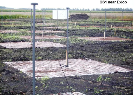
The first LOFAR station near Exloo Core Station 1 (CS1) (Fig. 6) was installed in summer 2006. CS1 differs from a standard LOFAR station as just 48 LBAs were so far in-stalled. 48 more LBAs were distributed on nearby station locations for interferometric test purpose. Fibre connections to theIBM Blue Gene/L in Groningen were in place. The CS1 saw its ”first light” in September 2006.
The sensitivity of the completed LOFAR exceeds that of any other long wavelength facility by up to about two order of magnitudes. According to Falcke et al. (2006) LOFAR’s sensitivity after one hour of integration time, using a band-width of 4 MHz and dual polarization is 2, 1.3, 0.07 and 0.06 mJy for 30, 75, 120 and 200 MHz, respectively. The angular resolution being achieved with LOFAR depends on the wavelength of the observation and the maximum base-lines available. Table 1 lists expected angular resolutions as a function of wavelength for the LOFAR core, the Dutch LO-FAR extending to about 100 km and the baseline CS1 - Ef-felsberg (IS-G1) of 260 km, which will be available soon.
The full digital concept of LOFAR allows to observe with eight independent station beams at the same time. This is realized by combining selected subbands in a station by a digital beamformer.
Some details of the LBA field can be seen from the CS1 image (Fig. 6). Each element is placed on a 3 m×3 m
ground plane. A plastic foil prevents plants to grow up. Two orthogonal dipoles are fixed by tent pegs and are connected to the LNAs, where two cables run down the central post and further underground to the LOFAR cabinet seen in the back of Fig. 6. This special air-conditioned outdoor cabinet is well shielded suppressing RFI transmission by about 40 dB.
Fig. 4. Overview of the likely distribution of stations in the core area of LOFAR, which is located in a flat area with rural environment near Exloo/Netherlands. In the core area the density of LOFAR stations is highest. The two antenna fields (LBA and HBA) for each station are indicated.
the village of Exloo. Figure 4 shows the actual plan for the distribution of stations for the innermost area. The station density is highest at its core and decreases with increasing distance from Exloo. The planned distribution of stations in the Netherlands is shown in Fig. 5.
The first LOFAR station near Exloo Core Station 1 (CS1) (Fig. 6) was installed in summer 2006. CS1 differs from a standard LOFAR station as just 48 LBAs were so far in-stalled. 48 more LBAs were distributed on nearby station locations for interferometric test purpose. Fibre connections to the IBM Blue Gene/L in Groningen were in place. The CS1 saw its “first light” in September 2006.
The sensitivity of the completed LOFAR exceeds that of any other long wavelength facility by up to about two order of magnitudes. According to Falcke et al. (2006) LOFAR’s sensitivity after one hour of integration time, using a band-width of 4 MHz and dual polarization is 2, 1.3, 0.07 and 0.06 mJy for 30, 75, 120 and 200 MHz, respectively. The angular resolution being achieved with LOFAR depends on the wavelength of the observation and the maximum base-lines available. Table 1 lists expected angular resolutions as
W. Reich: LOFAR in Germany 3
Fig. 4.Overview of the likely distribution of stations in the core area of LOFAR, which is located in a flat area with rural environment near Exloo/Netherlands. In the core area the density of LOFAR stations is highest. The two antenna fields (LBA and HBA) for each station are indicated.
Fig. 5.The planned distribution of LOFAR stations in the Nether-lands.
Table 1. Nominal angular resolution of the LOFAR array as a function of maximum baseline at low-band (30 MHz/75 MHz or λ 10 m/4 m) and at high-band (120 MHz/240 MHz or λ 2.5 m/1.25 m).
Baseline 30 MHz 75 MHz 120 MHz 240 MHz Core 1000” 400” 250” 125 ”
100 km 21” 8” 5” 3”
CS1 - IS-G1 8” 3” 2” 1”
1000 km 2” 0.”8 0.”5 0.”3
stations. The enormous raw data volume of LOFAR requires real time processing. No storage of the raw data is planned and even the reduced data volume is very large, which re-quires their distribution to the various data centres soon after processing.
32 of the 77 LOFAR stations are placed at its core close to the village of Exloo. Fig. 4 shows the actual plan for the distribution of stations for the innermost area. The station density is highest at its core and decreases with increasing distance from Exloo. The planned distribution of stations in the Netherlands is shown in Fig. 5.
The first LOFAR station near Exloo Core Station 1 (CS1) (Fig. 6) was installed in summer 2006. CS1 differs from a standard LOFAR station as just 48 LBAs were so far in-stalled. 48 more LBAs were distributed on nearby station locations for interferometric test purpose. Fibre connections to theIBM Blue Gene/L in Groningen were in place. The CS1 saw its ”first light” in September 2006.
The sensitivity of the completed LOFAR exceeds that of any other long wavelength facility by up to about two order of magnitudes. According to Falcke et al. (2006) LOFAR’s sensitivity after one hour of integration time, using a band-width of 4 MHz and dual polarization is 2, 1.3, 0.07 and 0.06 mJy for 30, 75, 120 and 200 MHz, respectively. The angular resolution being achieved with LOFAR depends on the wavelength of the observation and the maximum base-lines available. Table 1 lists expected angular resolutions as a function of wavelength for the LOFAR core, the Dutch LO-FAR extending to about 100 km and the baseline CS1 - Ef-felsberg (IS-G1) of 260 km, which will be available soon.
The full digital concept of LOFAR allows to observe with eight independent station beams at the same time. This is realized by combining selected subbands in a station by a digital beamformer.
Some details of the LBA field can be seen from the CS1 image (Fig. 6). Each element is placed on a 3 m×3 m
ground plane. A plastic foil prevents plants to grow up. Two orthogonal dipoles are fixed by tent pegs and are connected to the LNAs, where two cables run down the central post and further underground to the LOFAR cabinet seen in the back of Fig. 6. This special air-conditioned outdoor cabinet is well shielded suppressing RFI transmission by about 40 dB.
Fig. 5. The planned distribution of LOFAR stations in the Nether-lands.
Table 1. Nominal angular resolution of the LOFAR array as a function of maximum baseline at low-band (30 MHz/75 MHz or λ 10 m/4 m) and at high-band (120 MHz/240 MHz or λ
2.5 m/1.25 m).
Baseline 30 MHz 75 MHz 120 MHz 240 MHz
Core 1000” 400” 250” 125”
100 km 21” 8” 5” 3”
CS1 - IS-G1 8” 3” 2” 1”
1000 km 2” 0.”8 0.”5 0.”3
a function of wavelength for the LOFAR core, the Dutch LO-FAR extending to about 100 km and the baseline CS1 - Ef-felsberg (IS-G1) of 260 km, which will be available soon.
The full digital concept of LOFAR allows to observe with eight independent station beams at the same time. This is realized by combining selected subbands in a station by a digital beamformer.
Some details of the LBA field can be seen from the CS1 image (Fig. 6). Each element is placed on a 3 m×3 m ground plane. A plastic foil prevents plants to grow up. Two orthog-onal dipoles are fixed by tent pegs and are connected to the LNAs, where two cables run down the central post and fur-ther underground to the LOFAR cabinet seen in the back of Fig. 6. This special air-conditioned outdoor cabinet is well shielded suppressing RFI transmission by about 40 dB.
3 GLOW – The German LOng Wavelength Consortium
ASTRON has started to realize LOFAR exclusively in the Netherlands, which is connected to funding conditions. The maximum LOFAR baselines in the Netherlands are of the order of about 100 km, which implies too low angular
Fig. 6. The first LOFAR station CS1 (Core Station 1) was com-pleted in summer 2006. This station has so far 48 LBAs. 48 more LBAs were distributed at some hundred metre distance for initial interferometric tests.
3 GLOW - The German LOng Wavelength Consortium
ASTRON has started to realize LOFAR exclusively in the Netherlands, which is connected to funding conditions. The maximum LOFAR baselines in the Netherlands are of the order of about 100 km, which implies too low angular reso-lutions (see Table 1) to realize many scientific aims. Already during early planning of the LOFAR project ASTRON initi-ated discussions with its neighbor countries seeking for their participation in LOFAR. A number of German astronomical and other research institutes quickly realized the scientific potential of LOFAR and expressed their interest to partici-pate in an extended, which means a European LOFAR. An overview on LOFAR and the German engagement was given by Br¨uggen et al. (2006) and by Beck and Reich (2006).
The Max-Planck-Institut f¨ur Radioastronomie agreed to lead and to coordinate a German consortium participating in LOFAR. The GLOW consortium formed on a meeting at the Astrophysical Institute Potsdam on May 5th, 2006. Ten institutes signed a Memorandum of Understanding (MoU), where the common interests of GLOW are formulated. The GLOW board consists of: M. Br¨uggen (IU Bremen, vice-chair), R. J. Dettmar (RUB Bochum), M. Steinmetz (AIP Potsdam), J. A. Zensus (MPIfR Bonn, chair). As the GLOW secretary R. Beck (MPIfR) was elected. A scientific work-ing group (chair: B. Ciardi, MPA Garchwork-ing) and a technical working group (chair: W. Reich, MPIfR) were also set on. Actual efforts by GLOW member institutes concentrate to se-cure funding of their LOFAR station and to prepare their in-stallation. The Forschungszentrum J¨ulich prepares for large storage capacities (about 1 PByte) for LOFAR data. The working groups are busy to finalize proposals for ’Key Sci-ence Projects’, discuss fibre connection issues of common interest and how to make use of D-Grid facilities in future.
4 Scientific aims of GLOW
The scientific aims of the GLOW members were collected in a ’White Paper’, which was published on behalf of GLOW by the MPIfR in 2005. A copy of the ’White Paper’ can be ordered from the MPIfR Bonn. There is a wide range of scientific interests from solar observations, Galactic and ex-tragalactic research and in particular to study the Epoch of Reionization (EoR). A possible detection of signatures from the EoR was the main trigger to set up LOFAR. In a com-panion paper R. Beck (this volume) describes the exciting aspects of LOFAR observations to investigate cosmic mag-netic fields, which will complement high frequency results.
During the first phase of LOFAR operation most of the available observing time will be granted to so called ’Key Science Projects’ (KSPs). Dutch astronomers have already defined four KSPs: EoR, Surveys, Transients and Cosmic rays. International participation in these KSPs is presently discussed. GLOW expressed high interest in KSPs on so-lar research, cosmic magnetism and observations of Galactic and extragalactic jets.
5 Planned GLOW stations
It was estimated that about 10 to 12 stations distributed across Germany are needed to achieve an optimum high resolution image quality for an extended LOFAR. End of 2006 concrete plans exist for the installation of seven sta-tions (Fig. 7). For some stasta-tions funding is not yet granted, but aside the Effelsberg station the Garching station (MPA), the Potsdam station (AIP) and the Tautenburg station (TLS) are funded and will be installed in due course. Actually in-tensive negotiations take place on the problem of the data transfer to the central processor in Groningen. The transfer of scientific data is not supported in Germany, while in some European countries it is actually free of charge. Renting fibre connections for the data link to Groningen will by far be the largest cost factor for the operation of the GLOW stations. Fig. 6. The first LOFAR station CS1 (Core Station 1) was
com-pleted in summer 2006. This station has so far 48 LBAs. 48 more LBAs were distributed at some hundred metre distance for initial interferometric tests.
lutions (see Table 1) to realize many scientific aims. Already during early planning of the LOFAR project ASTRON initi-ated discussions with its neighbor countries seeking for their participation in LOFAR. A number of German astronomical and other research institutes quickly realized the scientific potential of LOFAR and expressed their interest to partici-pate in an extended, which means a European LOFAR. An overview on LOFAR and the German engagement was given by Br¨uggen et al. (2006) and by Beck and Reich (2006).
The Max-Planck-Institut f¨ur Radioastronomie agreed to lead and to coordinate a German consortium participating in LOFAR. The GLOW consortium formed on a meeting at the Astrophysical Institute Potsdam on 5 May 2006. Ten institutes signed a Memorandum of Understanding (MoU), where the common interests of GLOW are formulated. The GLOW board consists of: M. Br¨uggen (IU Bremen, vice-chair), R. J. Dettmar (RUB Bochum), M. Steinmetz (AIP Potsdam), J. A. Zensus (MPIfR Bonn, chair). As the GLOW secretary R. Beck (MPIfR) was elected. A scientific work-ing group (chair: B. Ciardi, MPA Garchwork-ing) and a technical working group (chair: W. Reich, MPIfR) were also set on. Actual efforts by GLOW member institutes concentrate to se-cure funding of their LOFAR station and to prepare their in-stallation. The Forschungszentrum J¨ulich prepares for large storage capacities (about 1 PByte) for LOFAR data. The working groups are busy to finalize proposals for “Key Sci-ence Projects”, discuss fibre connection issues of common interest and how to make use of D-Grid facilities in future.
4 Scientific aims of GLOW
The scientific aims of the GLOW members were collected in a “White Paper”, which was published on behalf of GLOW Fig. 6. The first LOFAR station CS1 (Core Station 1) was com-pleted in summer 2006. This station has so far 48 LBAs. 48 more LBAs were distributed at some hundred metre distance for initial interferometric tests.
3 GLOW - The German LOng Wavelength Consortium
ASTRON has started to realize LOFAR exclusively in the Netherlands, which is connected to funding conditions. The maximum LOFAR baselines in the Netherlands are of the order of about 100 km, which implies too low angular reso-lutions (see Table 1) to realize many scientific aims. Already during early planning of the LOFAR project ASTRON initi-ated discussions with its neighbor countries seeking for their participation in LOFAR. A number of German astronomical and other research institutes quickly realized the scientific potential of LOFAR and expressed their interest to partici-pate in an extended, which means a European LOFAR. An overview on LOFAR and the German engagement was given by Br¨uggen et al. (2006) and by Beck and Reich (2006).
The Max-Planck-Institut f¨ur Radioastronomie agreed to lead and to coordinate a German consortium participating in LOFAR. The GLOW consortium formed on a meeting at the Astrophysical Institute Potsdam on May 5th, 2006. Ten institutes signed a Memorandum of Understanding (MoU), where the common interests of GLOW are formulated. The GLOW board consists of: M. Br¨uggen (IU Bremen, vice-chair), R. J. Dettmar (RUB Bochum), M. Steinmetz (AIP Potsdam), J. A. Zensus (MPIfR Bonn, chair). As the GLOW secretary R. Beck (MPIfR) was elected. A scientific work-ing group (chair: B. Ciardi, MPA Garchwork-ing) and a technical working group (chair: W. Reich, MPIfR) were also set on. Actual efforts by GLOW member institutes concentrate to se-cure funding of their LOFAR station and to prepare their in-stallation. The Forschungszentrum J¨ulich prepares for large storage capacities (about 1 PByte) for LOFAR data. The working groups are busy to finalize proposals for ’Key Sci-ence Projects’, discuss fibre connection issues of common interest and how to make use of D-Grid facilities in future.
4 Scientific aims of GLOW
The scientific aims of the GLOW members were collected in a ’White Paper’, which was published on behalf of GLOW by the MPIfR in 2005. A copy of the ’White Paper’ can be ordered from the MPIfR Bonn. There is a wide range of scientific interests from solar observations, Galactic and ex-tragalactic research and in particular to study the Epoch of Reionization (EoR). A possible detection of signatures from the EoR was the main trigger to set up LOFAR. In a com-panion paper R. Beck (this volume) describes the exciting aspects of LOFAR observations to investigate cosmic mag-netic fields, which will complement high frequency results.
During the first phase of LOFAR operation most of the available observing time will be granted to so called ’Key Science Projects’ (KSPs). Dutch astronomers have already defined four KSPs: EoR, Surveys, Transients and Cosmic rays. International participation in these KSPs is presently discussed. GLOW expressed high interest in KSPs on so-lar research, cosmic magnetism and observations of Galactic and extragalactic jets.
5 Planned GLOW stations
It was estimated that about 10 to 12 stations distributed across Germany are needed to achieve an optimum high resolution image quality for an extended LOFAR. End of 2006 concrete plans exist for the installation of seven sta-tions (Fig. 7). For some stasta-tions funding is not yet granted, but aside the Effelsberg station the Garching station (MPA), the Potsdam station (AIP) and the Tautenburg station (TLS) are funded and will be installed in due course. Actually in-tensive negotiations take place on the problem of the data transfer to the central processor in Groningen. The transfer of scientific data is not supported in Germany, while in some European countries it is actually free of charge. Renting fibre connections for the data link to Groningen will by far be the largest cost factor for the operation of the GLOW stations. by the MPIfR in 2005. A copy of the “White Paper” can be ordered from the MPIfR Bonn. There is a wide range of scientific interests from solar observations, Galactic and ex-tragalactic research and in particular to study the Epoch of Reionization (EoR). A possible detection of signatures from the EoR was the main trigger to set up LOFAR. In a com-panion paper (Beck, this volume) describes the exciting as-pects of LOFAR observations to investigate cosmic magnetic fields, which will complement high frequency results.
During the first phase of LOFAR operation most of the available observing time will be granted to so called “Key Science Projects” (KSPs). Dutch astronomers have already defined four KSPs: EoR, Surveys, Transients and Cosmic rays. International participation in these KSPs is presently discussed. GLOW expressed high interest in KSPs on so-lar research, cosmic magnetism and observations of Galactic and extragalactic jets.
5 Planned GLOW stations
It was estimated that about 10 to 12 stations distributed across Germany are needed to achieve an optimum high resolution image quality for an extended LOFAR. End of 2006 concrete plans exist for the installation of seven sta-tions (Fig. 7). For some stasta-tions funding is not yet granted, but aside the Effelsberg station the Garching station (MPA), the Potsdam station (AIP) and the Tautenburg station (TLS) are funded and will be installed in due course. Actually in-tensive negotiations take place on the problem of the data transfer to the central processor in Groningen. The transfer of scientific data is not supported in Germany, while in some European countries it is actually free of charge. Renting fibre connections for the data link to Groningen will by far be the largest cost factor for the operation of the GLOW stations. Funds are required to allow a large number of institutes to participate in LOFAR.
W. Reich: LOFAR in Germany 411
W. Reich: LOFAR in Germany 5
Fig. 7. Location of the actually planned LOFAR station by the GLOW consortium. The LOFAR core in Exloo is also shown (AIP).
Fig. 8.Horizon for the LOFAR LBA field at Effelsberg. Optimum RFI shielding is expected towards east and west.
Funds are required to allow a large number of institutes to participate in LOFAR.
6 The Effelsberg LOFAR station
Following the CS1 the second LOFAR station ’IS-G1’ is ac-tually placed about∼ 200m south of the Effelsberg 100 m
Fig. 9. ASTRON equipment to measure low frequency RFI is placed at the Effelsberg LOFAR site.
telescope. The LOFAR site is a valley open to the south and the available area is just wide enough to place a complete LOFAR field.
The advantage of a valley is a certain level of protec-tion against terrestrial interference, which might become a limiting factor for sensitive observations in the long wave-length range of LOFAR. However, this means a somewhat restricted field of view. Fig. 8 shows the measured hori-zon at the approximate centre of the low-band field. Mo-bile RFI equipment provided by ASTRON (Fig. 9) was used for a successful two day RFI-measurement campaign in May 2006 by ASTRON personal, which proves the site to be well suited for LOFAR observations. However, another aspect must be considered at the Effelsberg site as the 100-m tele-scope with its outstanding sensitivity eventually will suffer from RFI generated by the LOFAR electronics, where the standard shielding might be not sufficient. It was therefore decided to place the standard LOFAR container in a much bigger (size:9 m × 5 m × 2.5 m), isolated and completely welded container, where depending on the actual RFI situa-tion a maximum addisitua-tional shielding of about 60 dB can be obtained.
The distribution of the 96 elements within the LBA field is the same as for the CS1, where the main sub-field, however, has 48 elements. The positions of the IS-G1 LBAs is rotated by 65◦ (Fig. 10) relative to the CS1 positions. Each of the following stations will have a different rotation angle. This Fig. 7. Location of the actually planned LOFAR station by the
GLOW consortium. The LOFAR core in Exloo is also shown (AIP).
W. Reich: LOFAR in Germany 5
Fig. 7. Location of the actually planned LOFAR station by the GLOW consortium. The LOFAR core in Exloo is also shown (AIP).
Fig. 8. Horizon for the LOFAR LBA field at Effelsberg. Optimum RFI shielding is expected towards east and west.
Funds are required to allow a large number of institutes to participate in LOFAR.
6 The Effelsberg LOFAR station
Following the CS1 the second LOFAR station ’IS-G1’ is ac-tually placed about∼200m south of the Effelsberg 100 m
Fig. 9. ASTRON equipment to measure low frequency RFI is placed at the Effelsberg LOFAR site.
telescope. The LOFAR site is a valley open to the south and the available area is just wide enough to place a complete LOFAR field.
The advantage of a valley is a certain level of protec-tion against terrestrial interference, which might become a limiting factor for sensitive observations in the long wave-length range of LOFAR. However, this means a somewhat restricted field of view. Fig. 8 shows the measured hori-zon at the approximate centre of the low-band field. Mo-bile RFI equipment provided by ASTRON (Fig. 9) was used for a successful two day RFI-measurement campaign in May 2006 by ASTRON personal, which proves the site to be well suited for LOFAR observations. However, another aspect must be considered at the Effelsberg site as the 100-m tele-scope with its outstanding sensitivity eventually will suffer from RFI generated by the LOFAR electronics, where the standard shielding might be not sufficient. It was therefore decided to place the standard LOFAR container in a much bigger (size:9 m × 5 m × 2.5 m), isolated and completely welded container, where depending on the actual RFI situa-tion a maximum addisitua-tional shielding of about 60 dB can be obtained.
The distribution of the 96 elements within the LBA field is the same as for the CS1, where the main sub-field, however, has 48 elements. The positions of the IS-G1 LBAs is rotated by 65◦ (Fig. 10) relative to the CS1 positions. Each of the following stations will have a different rotation angle. This Fig. 8. Horizon for the LOFAR LBA field at Effelsberg. Optimum
RFI shielding is expected towards east and west.
6 The Effelsberg LOFAR station
Following the CS1 the second LOFAR station “IS-G1” is ac-tually placed about∼200 m south of the Effelsberg 100 m telescope. The LOFAR site is a valley open to the south and the available area is just wide enough to place a complete
W. Reich: LOFAR in Germany 5
Fig. 7. Location of the actually planned LOFAR station by the GLOW consortium. The LOFAR core in Exloo is also shown (AIP).
Fig. 8.Horizon for the LOFAR LBA field at Effelsberg. Optimum RFI shielding is expected towards east and west.
Funds are required to allow a large number of institutes to participate in LOFAR.
6 The Effelsberg LOFAR station
Following the CS1 the second LOFAR station ’IS-G1’ is ac-tually placed about∼ 200m south of the Effelsberg 100 m
Fig. 9. ASTRON equipment to measure low frequency RFI is placed at the Effelsberg LOFAR site.
telescope. The LOFAR site is a valley open to the south and the available area is just wide enough to place a complete LOFAR field.
The advantage of a valley is a certain level of protec-tion against terrestrial interference, which might become a limiting factor for sensitive observations in the long wave-length range of LOFAR. However, this means a somewhat restricted field of view. Fig. 8 shows the measured hori-zon at the approximate centre of the low-band field. Mo-bile RFI equipment provided by ASTRON (Fig. 9) was used for a successful two day RFI-measurement campaign in May 2006 by ASTRON personal, which proves the site to be well suited for LOFAR observations. However, another aspect must be considered at the Effelsberg site as the 100-m tele-scope with its outstanding sensitivity eventually will suffer from RFI generated by the LOFAR electronics, where the standard shielding might be not sufficient. It was therefore decided to place the standard LOFAR container in a much bigger (size:9 m × 5 m × 2.5 m), isolated and completely welded container, where depending on the actual RFI situa-tion a maximum addisitua-tional shielding of about 60 dB can be obtained.
The distribution of the 96 elements within the LBA field is the same as for the CS1, where the main sub-field, however, has 48 elements. The positions of the IS-G1 LBAs is rotated by 65◦ (Fig. 10) relative to the CS1 positions. Each of the following stations will have a different rotation angle. This Fig. 9. ASTRON equipment to measure low frequency RFI is placed at the Effelsberg LOFAR site.
LOFAR field.
The advantage of a valley is a certain level of protection against terrestrial interference, which might become a limit-ing factor for sensitive observations in the long wavelength range of LOFAR. However, this means a somewhat restricted field of view. Fig. 8 shows the measured horizon at the ap-proximate centre of the low-band field. Mobile RFI equip-ment provided by ASTRON (Fig. 9) was used for a success-ful two day RFI-measurement campaign in May 2006 by ASTRON personal, which proves the site to be well suited for LOFAR observations. However, another aspect must be considered at the Effelsberg site as the 100-m telescope with its outstanding sensitivity eventually will suffer from RFI generated by the LOFAR electronics, where the standard shielding might be not sufficient. It was therefore decided to place the standard LOFAR container in a much bigger (size: 9 m×5 m×2.5 m), isolated and completely welded container, where depending on the actual RFI situation a maximum ad-ditional shielding of about 60 dB can be obtained.
The distribution of the 96 elements within the LBA field is the same as for the CS1, where the main sub-field, however, has 48 elements. The positions of the IS-G1 LBAs is rotated by 65◦(Fig. 10) relative to the CS1 positions. Each of the following stations will have a different rotation angle. This angle of 65◦gives a minimum east-west extent, which fits in the local requirements due to a number of late environmental
Fig. 10. The distribution of LBAs of the Effelsberg LOFAR sta-tion, which is rotated by 65◦relative to that of the CS1 station near Exloo.
angle of 65◦gives a minimum east-west extent, which fits in the local requirements due to a number of late environmental restrictions. The IS-G1 site is meanwhile (December 2006) prepared for the required flatness within a few cm, which was difficult to achieve for the dense, rather stony ground at the Effelsberg site.
Funded by the Max-Planck-Gesellschaft the required fi-bre connection from the LOFAR station to the MPIfR Bonn will be installed in 2007. Further data transfer from Bonn to Groningen will be realized by renting existing fibre links. The fibre connection Effelsberg - Bonn will be shared by us-ing it also for eVLBI experiments where the 100-m telescope is involved in. These data are further transferred from Bonn to the JIVE correlator located at Dwingeloo/Netherlands.
In December 2006 MPIfR, ASTRON and the LOFAR Foundation signed a MoU on the cooperation in placing and operating the Effelsberg ’IS-G1’ station. Common interfero-metric observations between the CS1 and the IS-G1 are also agreed on as well as the common development of the so called ’stand-alone’ mode for a LOFAR station. In this mode a LOFAR station is operated as a quasi ’single-dish’ tele-scope, whose mode is of interest for most GLOW stations as well. A software interface is being developed aiming to ana-lyze LOFAR station data with tools as they are available for observations with the Effelsberg 100 m telescope.
7 Conclusions
LOFAR is the first large digital radio telescope where many ambitious technical needs are going to be realized. Huge data streams have to be transferred across Europe and have to be processed by a dedicated supercomputer in real time. LOFAR promises revolutionary insights into the formation of the early Universe and will solve a number of astronom-ical key questions by its capability to observe at low radio frequency with unprecedented sensitivity.
The new technique realized with LOFAR and the opera-tional experience will provide important constraints for the concept of the Square Kilometre Array (SKA), which is an international project expected to be realized in the next decade (see e.g. Beck, 2006). The SKA with one square kilometre collecting area will become the major international radio astronomical facility in the world.
Acknowledgements. I appreciate the close cooperation with AS-TRON on all LOFAR related aspects and in particular Corina Vogt (LOFAR Science Office), who also provided Figs. 2 to 5 (copyright: ASTRON). I like to thank many colleagues at the MPIfR for their engagement in the installation of the LOFAR station at Effelsberg and preparing for its operation.
References
Beck, R.: Sterne und Weltraum, 9, 22–33, 2006
Beck, R. and Reich, W.: Sterne und Weltraum, 9, 19–21, 2006 Bregmann, J. D.: in Proc. SPIE Vol. 4015, Radio Telescopes, ed.
H.R. Butcher, 19–32, 2000
Br¨uggen, M., Beck, R. and Falcke, H.: Reviews of Modern Astron-omy, 19, 277–292, 2006
Falcke, H., van Haarlem, M. P., de Bruyn, A. G. et al.: in ’High-lights of Astronomy’, Vol. 14., XXVth IAU Genral Assembly, ed. K.A. van der Hucht, 119–120, 2006
Fig. 10. The distribution of LBAs of the Effelsberg LOFAR sta-tion, which is rotated by 65◦relative to that of the CS1 station near Exloo.
restrictions. The IS-G1 site is meanwhile (December 2006) prepared for the required flatness within a few cm, which was difficult to achieve for the dense, rather stony ground at the Effelsberg site.
Funded by the Max-Planck-Gesellschaft the required fi-bre connection from the LOFAR station to the MPIfR Bonn will be installed in 2007. Further data transfer from Bonn to Groningen will be realized by renting existing fibre links. The fibre connection Effelsberg - Bonn will be shared by us-ing it also for eVLBI experiments where the 100-m telescope is involved in. These data are further transferred from Bonn to the JIVE correlator located at Dwingeloo/Netherlands.
In December 2006 MPIfR, ASTRON and the LOFAR Foundation signed a MoU on the cooperation in placing and operating the Effelsberg “IS-G1” station. Common inter-ferometric observations between the CS1 and the IS-G1 are also agreed on as well as the common development of the so called “stand-alone” mode for a LOFAR station. In this mode a LOFAR station is operated as a quasi “single-dish” telescope, whose mode is of interest for most GLOW stations as well. A software interface is being developed aiming to analyze LOFAR station data with tools as they are available for observations with the Effelsberg 100 m telescope.
7 Conclusions
LOFAR is the first large digital radio telescope where many ambitious technical needs are going to be realized. Huge data streams have to be transferred across Europe and have to be processed by a dedicated supercomputer in real time. LOFAR promises revolutionary insights into the formation of the early Universe and will solve a number of astronom-ical key questions by its capability to observe at low radio frequency with unprecedented sensitivity.
The new technique realized with LOFAR and the opera-tional experience will provide important constraints for the concept of the Square Kilometre Array (SKA), which is an international project expected to be realized in the next decade (see e.g. Beck, 2006). The SKA with one square kilometre collecting area will become the major international radio astronomical facility in the world.
Acknowledgements. I appreciate the close cooperation with
AS-TRON on all LOFAR related aspects and in particular Corina Vogt (LOFAR Science Office), who also provided Figs. 2 to 5 (copyright: ASTRON). I like to thank many colleagues at the MPIfR for their engagement in the installation of the LOFAR station at Effelsberg and preparing for its operation.
References
Beck, R.: Sterne und Weltraum, 9, 22–33, 2006.
Beck, R. and Reich, W.: Sterne und Weltraum, 9, 19–21, 2006. Bregmann, J. D.: in Proc. SPIE Vol. 4015, Radio Telescopes, edited
by: Butcher, H. R., 19–32, 2000.
Br¨uggen, M., Beck, R., and Falcke, H.: Reviews of Modern Astron-omy, 19, 277–292, 2006.
Falcke, H., van Haarlem, M. P., de Bruyn, A. G. et al.: in: High-lights of Astronomy, 14, XXVth IAU General Assembly, edited by van der Hucht, K. A., 119–120, 2006.