http: // www.ijrtsm.com© International Journal of Recent Technology Science & Management 1
IJRTSM
INTERNATIONAL JOURNAL OF RECENT TECHNOLOGY SCIENCE & MANAGEMENT
“DESIGN AND ANALYSIS OF STACKER FORK ARMS USING ANSYS
SOFTWARE”
Utkarsha Shinde
1, Ashish Kumar Sinha
21M. Tech Scholar, Mechanical Engineering Dept., Oriental Institute of Science & Technology Bhopal,(M.P.), India
2Assistant Professor, Mechanical Engineering Dept., Oriental Institute of Science & Technology, Bhopal,(M.P.), India
Email: [email protected]1
ABSTRACT
In this paper, we studied the manufacturing process and functional activities of electric operated Stacker machine and came across with the various problems and handling in the current system. After thorough studies, careful static analysis and reviews of the various manufacturing systems and technologies. In this work an attempt is made to design of semi automatic Stacker. Semi automatic stacker is robust in construction and is smooth in operations. Semi automatic stacker is able to work efficiently for pallets on high rack, smooth control of precise lifting and lowering. By this project man power effort and time can reduce. And optimization weight of machinery. We design and analyze of carriage fork. Our aim is design and develops a model of semi automatic stacker. This system has a significant importance in the equipment and material handling system.
KEYWORDS: Stacker, manufacturing, lifting, static analysis, Semi automated, fork lifter, Optimization
I.
I
NTRODUCTIONMaterial handling (MH) involves ―short-distance movement that usually takes place within the confines of a building such as a plant or a warehouse and between a building and a transportation agency.‖1It can be used to create ―time and place utility‖
through the handling, storage, and control of material, as distinct from manufacturing (i.e., fabrication and assembly operations), which creates ―form utility‖ by changing the shape, form, and makeup of material.
It is often said that MH only adds to the cost of a product, it does not add to the value of a product. Although MH does not provide a product with form utility, the time and place utility provided by MH can add real value to a product, i.e., the value of a product can increase after MH has taken place; for example:
http: // www.ijrtsm.com© International Journal of Recent Technology Science & Management 2
Balanced Electric Stacker can fit into tight spaces. Extremely durable and budget friendly, the Toyota Counter-Balanced Stacker can help increase both your uptime and your bottom line.
Fig. 1
II.
COMPONENTS
OF
STACKER
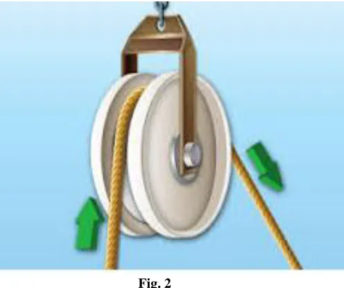
2.1 Pulley
A pulley is a wheel on an axle or shaft that is designed to support movement and change of direction of a taut cable, supporting shell is referred to as a block.
Fig. 2
2.2 Hook
http: // www.ijrtsm.com© International Journal of Recent Technology Science & Management 3
Fig 3
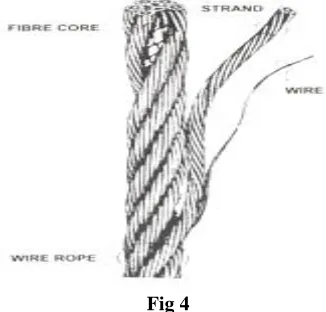
2.3 Wire rope
Wire rope is rope made from wire. It consists of several strands of metal wire laid (twisted) into a helix.
Fig 4
2.4 DC Motor
A DC motor is any of a class of rotary electrical machines that converts direct current electrical energy into mechanical
energy. The most common types rely on the forces produced by magnetic fields. Nearly all types of DC motors have some internal mechanism, either electromechanical or electronic, to periodically change the direction of current flow in part of the motor.
http: // www.ijrtsm.com© International Journal of Recent Technology Science & Management 4
III.
S
TACKERS
PECIFICATIONS Table.1IV.
MOTOR
POWER
CALCULATION
FOR
LIFTING
Power = Force = mass x acceleration.
= 100 x 9.81
= 981 N
Work done = Force x Lifting Height
= 981 x0.300
= 294.3 Nm
Power = Work done / Time Taken
=294.3/ 1
= 294.3 W
Safety Factor = 1.2
http: // www.ijrtsm.com© International Journal of Recent Technology Science & Management 5
=353 W
=0.47 hp ( 1 HP = 746 Watt)
4
.1
Structural Steel Mechanical properties
Table 2
Material Field
Variable Value Units
Density 7850 Kg/m3
Young’s modulus 2E+05 Mpa
Poisson Ratio 0.30
Shear modulus 76923 Mpa
Bulk Modulus 1.6667E+05 Mpa
Tensile Yield Strength 250 Mpa
Compressive Yield
Strength 250 Mpa
Tensile Ultimate
Strength 460 Mpa
Compressive Ultimate
Strength 0 Mpa
V.
COMPONANT
STUDY
http: // www.ijrtsm.com© International Journal of Recent Technology Science & Management 6
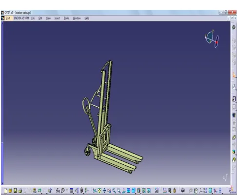
Fig.7 Fork lifter arm 3D model
VI.
SIMULATION
&
ANALYSIS
6.1 Structural steel materials
http: // www.ijrtsm.com© International Journal of Recent Technology Science & Management 7
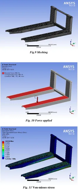
Fig.9 Meshing
Fig. 10 Force applied
http: // www.ijrtsm.com© International Journal of Recent Technology Science & Management 8
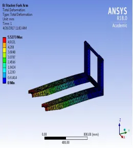
Fig.12 Deformation
6.2Stainless steel materials
http: // www.ijrtsm.com© International Journal of Recent Technology Science & Management 9
Fig.14 Deformation
6.3 Aluminum Alloy
http: // www.ijrtsm.com© International Journal of Recent Technology Science & Management 10
Fig.16 Deformation
6.4 Magnesium Materials
http: // www.ijrtsm.com© International Journal of Recent Technology Science & Management 11
Fig.18 Deformation
VII.
RESULT
&
DISCUSSION
Fully automatic Stackers are robust in construction and are smooth in operations. Fully automatic stackers are able to work efficiently for pallets on high rack. Smooth control of precise lifting and lowering. By this project man power effort can be reduce and time of work can reduce. And we designed and analyzed of carriage fork and power pack box with different load. This system has a significant importance on the equipment and material handling system. Considered the aspects of noise and vibration. The objective of this work is to present an improved methodology, based on numerical and experimental analysis; to evaluate the life of the semiautomatic stacker system. It can be improving the industrial work. and also improve the material handling equipment system. In the last several years’ material handling has become a new, complex, and rapidly evolving science. For moving material in and out of warehouse many types of equipment and system are in use, depending on the type of products and volume to be handled. The equipment issued, in loading and unloading operations, for movement of goods over short distances. The handling of material in warehouse is restricted to unitized forms, which require smaller size equipment. However, for bulk handling of material at logistics nodes such as fully automatic stacker can be used for the appropriate need of improved industry.
Materials comparisons Table.3
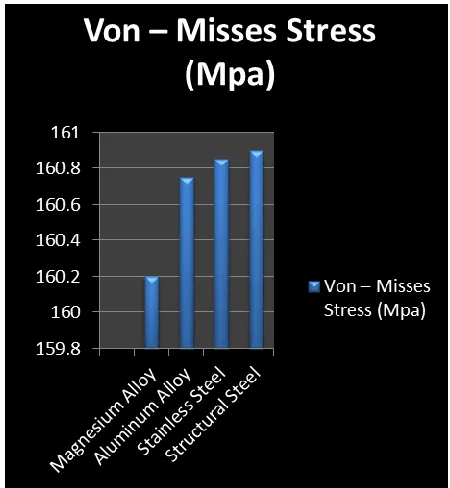
S. No. Materials Von – Misses Stress
(Mpa)
Deformation
(mm)
01 Structural Steel 160.9 5.33
02 Stainless Steel 160.85 5.52
03 Aluminum Alloy 160.75 14.99
http: // www.ijrtsm.com© International Journal of Recent Technology Science & Management 12
Fig.19 Comparison of Von –misses stress for different materials
http: // www.ijrtsm.com© International Journal of Recent Technology Science & Management 13
7.1
Comparison between our model and exiting model
Table.4
7.2 Advantages
1. Simple in construction.
2. Simple and convenient lifting operating system.
3. Light and easy manual steering system, equipped with a parking brake.
4. Smooth control of precise lifting and lowering.
5. Special design is available according to customers’ requirements.
REFERENCES
1. Blackstone CEJ (1998) The development of overhead crane robotics for automated handling and storage. In: Proceedings of the Institute of Mechanical Engineers, International Conference on Advance Handling Systems, London, 24–25 May
http: // www.ijrtsm.com© International Journal of Recent Technology Science & Management 14
3. Loscam Limited (2003) Standard pallet. www.loscam.com/standard_pallet.htm, Box Hill, Victoria, Australia, cited November 2003.
4. McCurdy DR, Phelps JE (1995) Characteristics of pallet use in the US. Department of Forestry, Southern Illinois University, Carbondale, Illinois
5. National Wooden Pallet and Container Association (1997) Pallet users view plastic as the wave of the future. Pallet Talk Newsletter 97(7):14–15
6. White MS (1996) Comparative performance of timber, structural panel deck, plastic and corrugated paperboard pallet. Pallet and Container Research Laboratory, Virginia Polytechnic Institute and State University, Blacksburg, Virginia
7. Granta Design Limited (2001) CES Selector 4.0. Material Properties Data Software, Cambridge, UK
8. Higham R (1971) A handbook of paperboard and board. Business Books Ltd, London
9. Patricio MA, Maravall D. A novel generalization of the gray-scale histogram and its application to the automated visual measurement and inspection of wooden pallets. J Image Vision Comput 2007; 25:805–16.
10. Kabir MF, Schmoldt DL, Araman PA, Schafer ME, Lee SM. Classifying defects in pallet stringers by ultrasonic scanning. J Wood Fiber Sci 2003;35:341–50.
11. Kabir MF, Schmoldt DL, Schafer ME. Time domain ultrasonic signal characterization for defects in thin unsurfaced hardwood lumber. J Wood Fiber Sci 2003;34:165–82.
12. Lebowitz CA, Baaklini GY. Nondestructive evaluation of materials and composites. Bellingham: SPIE Publication; 1996.
13. Pallet reduction and reuse technical appendices; 1996.
14. Khoo TS, Ratnam MM, AbdulKhalil HPS. Wood filler (WF)–recycled polypropylene (RPP) composite pallet: study of static deformation using fea and shadow moire. J Reinf Plast Compos 2008;27:1733–44.
15. Mcoy M. Pallets that make the extra trip, New York; 2003.
16. Clarke JW. Pallets 10: 1Industry overview and wood, plastic, paper, and metal
17. Khoo TS, Ratnam MM, Shahnaz SAB, AbdulKhalil HPS. Wood filler–recycled polypropylene (WF–RPP) composite pallet: study of fastening method. J Reinf Plast Compos 2008;27:1723–31.
18. Jafarian Jam N, Behravesh AH. Challenge to the production of fine wood– plastic injection molded composites. J Reinf Plast Compos 2008.
19. Jafarian Jam N, Behravesh AH. Flow behavior of HDPE–fine wood particles composites. J Thermoplast Compos Mater 2007;20:439–51
20. Markarian J. Material and processing developments drive wood plastic composites forward. J Plast Add Compd 2003:24–8.
21. Wechsler A, Hiziroglu S. Some of the properties of wood–plastic composites. JBuild Environ 2007;42:2637–44.
22. Pritchard G. Two technologies merge: wood plastic composites. J Plast AddCompd 2004;104:18–24.
23. Soury E. Design, optimization and manufacture of wood–plastic compositepallets, Faculty of Engineering, Tarbiat Modares University, Tehran; 2007.