R E S E A R C H
Open Access
Spatio-temporal consistent
depth-image-based rendering using layered depth image
and inpainting
Suryanarayana M. Muddala, Roger Olsson and Mårten Sjöström
*Abstract
Depth-image-based rendering (DIBR) is a commonly used method for synthesizing additional views using video-plus-depth (V+D) format. A critical issue with DIBR-based view synthesis is the lack of information behind foreground objects. This lack is manifested as disocclusions, holes, next to the foreground objects in rendered virtual views as a consequence of the virtual camera “seeing” behind the foreground object. The disocclusions are larger in the extrapolation case, i.e. the single camera case. Texture synthesis methods (inpainting methods) aim to fill these disocclusions by producing plausible texture content. However, virtual views inevitably exhibit both spatial and temporal inconsistencies at the filled disocclusion areas, depending on the scene content. In this paper, we propose a layered depth image (LDI) approach that improves the spatio-temporal consistency. In the process of LDI generation, depth information is used to classify the foreground and background in order to form a static scene sprite from a set of neighboring frames. Occlusions in the LDI are then identified and filled using inpainting, such that no disocclusions appear when the LDI data is rendered to a virtual view. In addition to the depth information, optical flow is computed to extract the stationary parts of the scene and to classify the occlusions in the inpainting process. Experimental results demonstrate that spatio-temporal inconsistencies are significantly reduced using the proposed method. Furthermore, subjective and objective qualities are improved compared to state-of-the-art reference methods.
Keywords: View synthesis, Depth-image-based rendering, Image inpainting, Texture synthesis, Hole filling, Disocclusions, Layered depth image, Temporal consistency
1 Introduction
Three-dimensional television (3DTV) and free viewpoint television (FTV) technologies are actively pursued in both research and compression standardization, which is sup-ported by the development of enabling display technolo-gies [1]. The 3DTV application aims to provide realistic depth impressions by presenting several views of a scene simultaneously from slightly different viewpoints. In com-parison, the FTV application offers users the ability to look around the scene by generating new views (in 2D or 3D) from any arbitrary position [2]. Hence, both applica-tions require the display of a large number of views, all from different viewpoints, in order to provide a smooth
*Correspondence: [email protected]
Department of Information and Communication Systems, Mid Sweden University, Holmgatan 10, 85170 Sundsvall, Sweden
transition between the views and thereby an immersive visual experience.
However, capturing and transmission of the required number of views is not a feasible solution from a bandwidth point-of-view. Therefore, view synthesis is employed as an efficient solution to produce the necessary number of views at the receiver side using a smaller set of captured and transmitted views. Depth-image-based ren-dering (DIBR) methods generate these views from formats such as plus-depth (V+D) and multiview video-plus-depth (MVD) [3]. In this work, we define the input views that a DIBR method operates on as original views and output views it produces as the virtual (i.e. rendered) views. A virtual view is produced using DIBR by utilizing texture (the 2D color information) and a corresponding depth image. Using geometrical 3D warping, which relies on knowledge about scene depth and camera parameters,
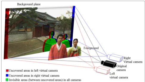
pixels from the original view are projected into the virtual view’s image plane. An illustration of the view rendering is shown in Fig. 1, where the V+D format is adopted.
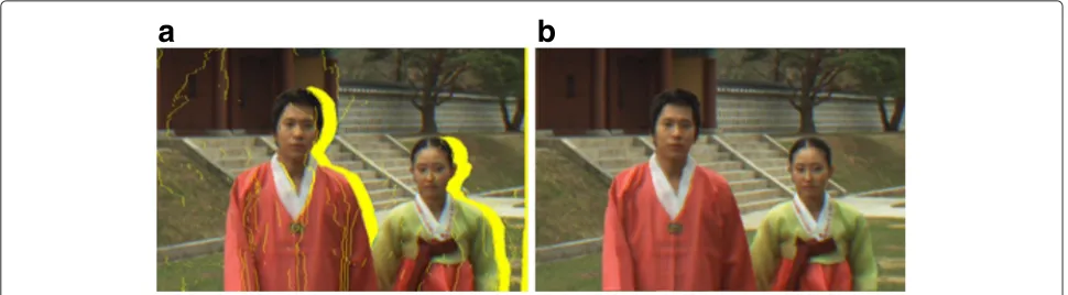
Warped images, which are rendered using DIBR, exhibit several artifacts due to the inherent properties of warp-ing as shown in Fig. 2a. DIBR artifacts are ghostwarp-ing and uncovered areas (i.e. holes). Ghosting artifacts are blended texture values caused by objects that are neighboring in the original view but becomes overlapped in the virtual view due to the depth and texture misalignments. A typ-ical cause of this misalignment is the noise introduced in the depth map around object borders, frequently occur-ring in depth from stereo matching. Ghosting artifacts also cause inconsistent hole filling. Holes are defined as pixels in the warped image that receives no texture val-ues from the forward warping process (see Fig. 2a). Holes can be classified into three groups:cracks,disocclusions andout-of-field areas. Cracks are holes of size one to two pixel wide caused by rounding the floating point position of a warped pixel to make it fit the pixel grid of the virtual view image plane. Disocclusions and out-of-field areas are holes of larger size caused by the depth discontinuities between objects within the scene and the limited field of view of the camera. The size of the holes increases as the distance between the original and warped camera view position increases. Dealing with disocclusions and out-of-field areas in a visually plausible manner is a much greater
challenge. In the next section, we will elaborate on how we address these problems.
In order to solve the problems caused by the holes, we use the following terminology. We define foreground as the part of the scene closer to the camera that occludes other objects and background to be the part of the scene farther from the camera partially occluded by the fore-ground. Disocclusions are occluded regions in the original view that are revealed in the virtual view as a result of warping. Disocclusions occur at the borders of the object depending on the relative position translation between the original and virtual view camera. Out-of-field areas are caused by the limited field of view in the original view and they occur at the image boundaries of the virtual view. Moreover, out-of-field areas usually occur in the linear camera set-ups, whereas in converging camera set-up may not. The size of the holes (disocclusions and out-of-field areas) increases when the size of the of the inter-camera distance (i.e. the baseline) increases.
1.1 Related work
The literature proposes several pre-processing and post-processing methods to overcome DIBR artifacts. Pre-processing methods smooth the depth map prior to warping using, e.g. symmetric or asymmetric Gaus-sian filter [4, 5]. However, pre-processing of the depth map may imply geometrical distortions in the warped
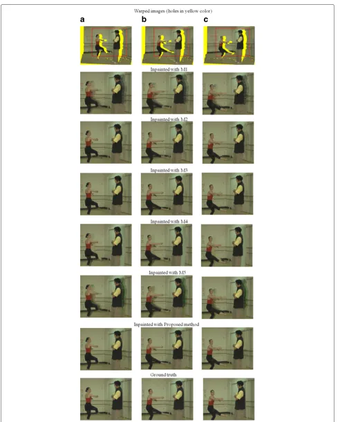
a
b
Fig. 2View synthesis results.aSynthesized image (holes inyellow color).bProposed synthesized image
image. However, post-processing techniques add com-plicated steps after warping in the warped image [6–9]. Image-domain warping methods are another way of reconstructing the virtual views using sparse disparity information [10, 11]. A number of methods combine both pre-processing and post-processing techniques to address rendering problems [8].
Several hole-filling methods have been proposed in the literature. In the context of virtual view synthesis from a single V+D, the hole-filling methods can be generally clas-sified into two groups. In the first group, the data required to fill the hole is synthesized from the image itself. We term this group spatial domain hole-filling method. In the second group, the data required to fill the hole is recov-ered from both the spatial and temporal domain, so we term them temporal domain hole-filling methods.
Spatial domain hole filling: Spatial domain hole-filling methods can be classified into interpolation, tion and image inpainting. Interpolation and extrapola-tion methods use the texture of neighbor pixels around the holes to fill missing areas in the warped images [12]. How-ever, for large holes, the results yield annoying artifacts and unnatural textures. In contrast, inpainting methods use structural and textural properties of the image in the neighborhood of the hole to fill missing areas [13, 14]. The view synthesis reference software (VSRS) is used in the standardization activities of 3DTV and FTV and com-bines various techniques to produce virtual views [15]. For example, VSRS applies a diffusion-based inpainting method to fill any holes. In general, diffusion methods suf-fer from the introduction of blurred results in the virtual image, more so when the hole is large. In addition, VSRS suffers from limitations in how foreground-background is identified during inpainting, which results in holes being partially filled with foreground textures, and not only background as appropriate. To reduce this problem, Oh et al. [16] replaced the foreground pixels on the boundary with background values.
To overcome the limitations of these diffusion methods, exemplar methods combine both structural and textural
properties when filling in missing areas [17]. In exem-plar methods, a filling order is first computed on the hole boundary using the number of known pixels in a patch (confidence term) and structure in the neighborhood (data term). Next, a highest priority patch (target patch) is selected to be filled using the best patch (source patch) from the neighborhood using patch matching. Although the exemplar method has the advantage of recovering the structure, this priority order is not suitable for hole filling in the view synthesis context, since holes should be filled only from the background texture. Several methods have been proposed by improving filling priorities and adding various foreground-background classification techniques in the exemplar methods including the methods in [18–23]. Despite improvements, these methods still have spatial texture inconsistencies and moreover, they severely suffer from temporal inconsistencies (flickering).
Another approach to filling missing areas is to generate the hole information in the original view before warping, instead of filling the holes after DIBR. This approach is similar to methods working with the layered depth video (LDV) format. LDV contains occlusion information along with V+D and share many properties with the layered depth image (LDI) [24]. The method in [25] has been pre-sented to generate this occlusion data from a stereo pair. Several ways to produce the necessary occlusion data from different camera set-ups are presented in [26]. However, an explicit way to produce LDI data from a single V+D is not presented. Recently, a method has been presented in [27] to generate LDI from V+D. Although this method has improved spatial consistency, it still suffers from flickering in the temporal domain.
motion vectors are sparse and do not correspond to the real motion, quality gains are limited. In other attempts, background sprites are generated by using the temporal frame information, after which disocclusions are filled and updated using the true texture and finally, inpainting is applied to fill holes in virtual views [29–32]. The method provided by Schmeing et al. requires a spatial hole fill-ing for disocclusions caused by static foregrounds [30]. Regardless, reusing the synthesized background from the sprite and inpainting the remaining holes at the moving foreground causes spatial inconsistencies. Another sprite-based hole-filling method presented in [33–35] extracts the static background information using depth classifi-cation by probability analysis, a Gaussian mixed model and structural similarity index. Yet, these methods are prone to exhibit spatio-temporal inconsistencies for mov-ing foreground objects. Hsu et al. proposed a method to construct the disocclusions using global optimization [36]. However, the results show spatial inconsistencies at the structured background due to the inpainting method used. Choi et al. used a method where the disocclu-sions are filled by finding the best patches in the past frames along with current frames [37]. This method yields spatially acceptable results but suffers from flickering arti-facts particularly when it comes to the static foreground objects.
Although the above-mentioned temporal hole-filling methods show improvements and new advances, they still suffer from spatial and temporal inconsistencies. These inconsistencies consequently deteriorate the visual quality of the virtual view.
In this paper, we propose a spatio-temporal consistent view synthesis method for extrapolating virtual views. The proposed method produces a layered depth image by identifying the occlusions and inpainting them in the original view using temporal information and motion esti-mation. When the layered depth image is rendered to the virtual view, no disocclusions appear and views are consistent in the spatial and temporal domain.
This paper is organized as follows: Section 2 explains the proposed spatio-temporal consistent view synthesis with inpainting. The experimental set-up and the evaluation criteria are described in Section 3. Results and analysis of the proposed method are presented in Section 4. Finally, in Section 5, we discuss challenges and conclude the work.
2 Proposed view synthesis method
Temporal inconsistencies are the result of filling holes in a frame irrespective of temporal information. To reduce the temporal inconsistencies, we construct a static scene sprite over time and fill the holes by using a depth-based inpainting method. The sprite is formed such that the occlusion information in the original view is generated in a spatially and temporally consistent manner. Using
the occlusion-free sprite, a LDI is generated such that no disocclusions will appear after warping.
In the sprite construction process, we have used a set of future frames, motion estimation, occlusion region, occlu-sion depth threshold and foreground-background classifi-cation. Future frames not only fetch the true information of the holes but also reduce temporal inconsistencies by adding a smoothing constraint. At each time instant t, the sprite makes use of information in all previous frames as well as future frames up to time instant t+ Bl. The buffer length Bl depends on the applications and must be selected accordingly. Initially, the sprite is constructed by considering the information in the first Bl frames by employing the process described below in this section. Then, the sprite is updated with new information of frame
(t+Bl)at each iteration. That is, the sprite always con-tains information from theBl future frames. After filling the sprite with this information, there are still holes to be filled. These holes are filled by employing the inpainting procedure described in Section 2.4. The inpainting pro-cedure is rather time-consuming and is therefore carried out everyBlframe. Both for information in a new frame and for inpainted data, the process gradually transforms the existing information with new information such that it is fully replaced at timet+Bl. The identified occlusion, occlusion depth threshold and foreground-background classification help in finding the background informa-tion to fill the holes from neighboring frames and guide the inpainting process to fill from background. As the global foreground-background classification is not con-sistent over time, motion estimation helps to construct the static scene sprite. Next, the holes in the sprite are labeled using motion estimation such that holes that share information in the temporal domain are filled with pre-vious inpainted information and the remaining holes are inpainted over a set of frames. This step not only guar-antees the temporal consistency but also improves the spatial consistency at moving foregrounds.
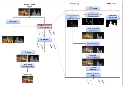
The proposed view synthesis method using LDI is shown in Fig. 3. The process of the method is as follows: first, a spatio-temporal consistent LDI is generated. Next, the LDI is warped and combined with the warped image. The final step consists of hole-filling post-processing. The details of each part are presented in the following sections. The LDI generates the occlusion layers in the original view, where the occlusions and depth thresholds from V+D are identified using the work of [27].
Fig. 3Proposed view synthesis method. Spatio-temporal consistent view snythesis using LDI and inpainting
The occlusions and the corresponding depth thresholds are identified as follows:
2.1.1 Depth discontinuity pixel identification
Disocclusions occur between pixels that are neighbor-ing in the original image, have a distinct difference in depth, and that become separated in the warped image. For example, the occlusion behind a foreground object in the original image becomes visible as a disocclusion in the virtual image. A disocclusion appears to the right of the foreground object (see Fig. 4), when the virtual image is rendered from a camera positioned to the right of the original camera.
Letbe the warping operation that projects the original view image Io to the virtual view image Iv. We define a depth discontinuity pixel (DDP) to be a neighboring pixel pair{fo,po} positioned in the original view as shown in Fig. 4 that satisfy the following conditions:
DDP= {fo,po};dv2> η, (1)
whereηis an occlusion threshold, anddvis a displacement vector given by
dv=
dx dy
=fv−pv, (2)
wherefv,pvare projected pixels in Iv:
:fo→fv, :po→pv.
(3)
The above definition of DDP is presented within the context of a right warped view. It is straightforward to change Eq. (1) for a left warped image. The summary of the notation used in this paper is presented in Table 1.
Fig. 4Identification of occlusion location
is labeled as background when its projected pixels dif-ference is less than its neighbor pixel in the overlapped DDP.
2.1.2 Occlusion identification
After identifying and labelling the DDPs, occlusions are located in the original image by horizontal and verti-cal displacements and their corresponding depth values. The occlusions at the DDP {po,fo} are identified as the following set:
O(DDP)= {p;p∈l∧(Z(p) > ξ)} (4) wherelis a line joining pixelspoandro = po−dv, and ξ is an occlusion depth threshold, given by the arithmetic mean over the DDP depths:
ξ = Z(fo)+Z(po)
2 , (5)
The full occlusion in the image consists of all such pixels:
O=
all DDP
O(DDP) (6)
An example of an occlusion is shown in Fig. 5d.
2.1.3 Occlusion depth threshold
Identified occlusions belong to the background and should be filled with consistent background information.
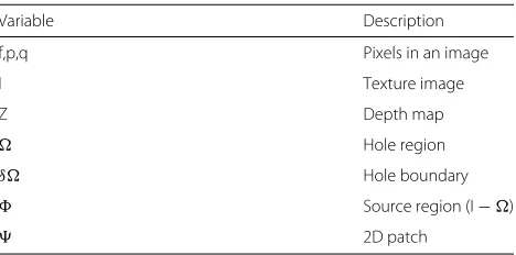
Table 1Notation
Variable Description
f,p,q Pixels in an image
I Texture image
Z Depth map
Hole region
δ Hole boundary
Source region (I−)
2D patch
Hence, two depth threshold images are created, ZAand ZB, which contain the average depth, and background depth values of the DDPs at occlusion areas, respectively:
ZA(q)=ξ, ZB(q)=Z(po),
∀q∈l, (7)
wherelis a line defined in Eq. (4). Note that pixels on dif-ferent lineslare calculated from different DDPs. Examples of ZAand ZBare shown in Fig. 5e, f.
2.2 Static scene sprite construction
The static scene sprite construction step builds a global sprite during the view synthesis process by collecting texture and depth information of the static scene from temporal frames. The global sprite consists of both the texture ISand depth ZS. The construction process contin-ues for a set of frames. The static information from the set of frames is extracted and stored in the constructed sprites IS and ZS. Example of texture sprite at different time instants is shown in Fig. 6. The remaining holes in the sprites are filled using the inpainting process.
The global sprite formation is guided by the follow-ing parameter specific for the sprite: The occlusionsOS indicate the holes, the occlusion threshold ZAS indi-cates allowable depth values to fill the holes, the global foreground-background classification FS identifies the absolute foreground-background and finally the motion pixelsMSindicate the moving objects.
We use a simple depth map segmentation on the whole image to identify the background in order to form the sprite with the background information [38]. The Otsu method selects an optimal threshold by maximizing the class variance and it works well when the entire dis-tribution is segmented into two classes. We denote the identified foreground pixels asF.
a
b
c
d
e
f
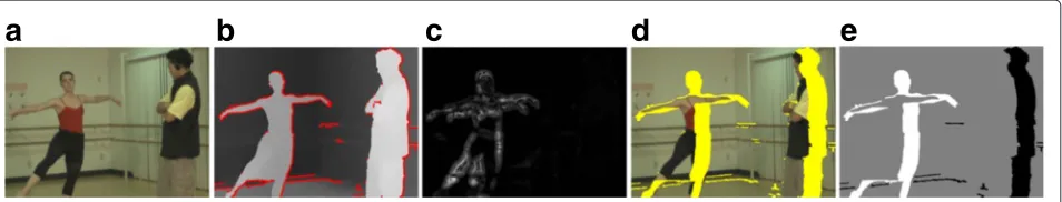
Fig. 5Occlusion layer identification and depth threshold generation.aOriginal image.bDepth discontinuity pixels (DDPs) (inred color).cOcclusion in original image (inyellow color).dOcclusion region.eAverage depth threshold image.fBackground depth threshold image. Note that the depth values in the threshold images are scaled for illustration purpose
objects in the scene. The optical flow describes the appar-ent motion of objects, surfaces and edges between images, so we use the Lukas-Kanade algorithm, a simple and efficient method [39]. The motion pixels are given by
M= {p;|V(p)|> ρ} (8)
where|V(p)|is the absolute optical flow value atp.ρis the optical flow threshold, which allows to change the noise sensitivity of the optical flow calculations.
The static sprite is formed in three steps: (i) Hole regions in the sprite are filled with the future frame using the occlusion depth threshold ZA. (ii) The foreground and moving information in the sprite are replaced by back-ground, static foreground and motion information. (iii)
Finally, the holes in the upcoming frame are located in the sprite using the depth threshold ZA. In the sprite construc-tion process of the static scene, the sprite is initialized with information from the first frame(t=0).
IS:=I0,
ZS:=Z0,
ZAS:=Z0A,
OS:=0O,
MS:=0M,
FS:=0F.
(9)
Once the sprite is initialized, the occlusions should be filled with new texture as it becomes available. Firstly,
a
b
c
Fig. 6Static scene sprites at different time instants. A static scene sprite is initialized with the first frame and updated with background information from subsequent frames at holes and foreground regions. Sprites after locating holes are in first row and sprites after inpainting are in second row;
the holes are filled with static background from the new frame:
IS(p):=It(p) ZS(p):=Zt(p)
∀p∈S\tO; Zt(p) <ZAS(p)
(10)
The set of occlusion pixels in the sprite OS are then updated by removing the pixels considered in Eq. (10). Next, the moving object pixels and foreground pixels in the sprite are replaced by information in the new frame:
IS(p):=It(p)
ZS(p):=Zt(p)
∀p∈MS∪FS; Zt(p) <ZS(p)−ϑ,
(11)
where ϑ is depth tolerance, which is set according to the variations of the scene depth. The set of motion and foreground pixels in the sprite, MS andFS, are then updated with the corresponding pixel information in the new frame.
Finally, the average depth threshold in the spriteZASis updated with the corresponding information of holes in the new framet:
ZAS(p)= ZS(p)+Z t A(p)
2 ,∀p∈
t
O; ZtA(p) >ZS(p),
(12)
whereby the set of occlusion pixels in the sprite,OS is updated with the corresponding pixel information in the new frame.
An example of texture sprite at different time instants is shown in Fig. 6. The remaining holes in the sprites are filled using the inpainting process.
2.3 Hole classification
Holes in each frame are classified as static and dynamic by using the motion of the foreground objects (see Fig. 7e). Holes which appear at the moving foreground objects are labeled dynamic holes. These holes are filled with either true texture from consequent frames or by the inpainting process. Holes which appear at static foreground objects are labeled static holes. Using this classification, static
holes are filled only once in the entire view synthesis pro-cess and are placed in the sprite to be reused when needed. In contrast, dynamic holes are inpainted over a set of frames in order for the inpainted texture to be spatially and temporally consistent with the background. As not all motion pixels belong to the foreground object that causes holes, only the pixels that belong to the dynamic holes are given by
D=p;p∈O(n)∧(νn> ρ) (13)
νn= 1
p∈En
max Vp, (14)
whereO(n)isnth hole in a occlusion region.Enis a set that contains the DDPs corresponding to thenth hole.νn is the average of maximum optical values in the patch cen-tered at DDPs on thenin a frame (see Fig. 7b).is the number of DDPs inEn.
Once the hole classification for the frames in the buffer are obtained, then the dynamic holes in the sprites are given byDS=OS∩D.
2.4 Inpainting
The holes remaining in the sprite, after compensating the true texture from the temporal information, are divided into small and large holes. This is because small holes will have no inpainting priority due to the foreground presence within a patch. As a result, small holes will not be filled until after the large holes have been filled. This implies inconsistent selection and filling of large holes when they lie within a search region of a given hole to find a best match. Therefore, small holes with a size smaller than a patch area are filled using the interpolation method. Then inpainting is applied on the large holes, where the inpaint-ing method is adopted from [27], which is derived from [17]. Note that the inpainting method is applied on the sprite instead of each frame. The steps of the inpainting process are as follows:
1. Identify the background boundary of the holes using the hole depth thresholdZAS.
a
b
c
d
e
a
b
c
d
e
2. Compute the priority on the background boundary using the curvature data term and depth-based confidence term and select a patch with the highest priority.
3. Find a good match to the target patch in both texture and depth. Fill holes in the target patch with a weighted combination of the best patches.
4. Update the terms and repeat the above steps until the holes in the sprite are filled.
In the next sections, we will give further details on the inpainting steps.
2.4.1 Foreground-background boundary extraction
The background boundary of the hole is identified by classifying the hole boundary into the foreground and background using the depth threshold image ZAS. The classification proceeds as follows: Initially, the hole boundary δ is obtained by applying a Laplacian con-volution on the hole region. Next, the hole boundary is classified into the foreground boundaryδF and the background boundaryδB, i.e.δ=δF∪δB.
Let us begin by defining the maximal value of the occlu-sion threshold on the 2D patch at pointp,p, coinciding with the source region:
μ=max ZAS(q)|q∈(p∩)
(15)
δF=δ ∀p: ZS(p) > μ, (16)
δB=δ−δF, (17)
2.4.2 Priority
The priority term on the background boundary is the product of confidence and data terms:
P(p)=Cz(p)·Dk(p), (18)
where Cz(p) is the depth-based confidence term, and Dk(p)is the curvature data term atp.
Depth-based confidence termcomputes the percentage of background pixels in a patch.
Cz(p)= 1
p
q∈p∩
C(q), (19)
C(q)=
1, q∈B;
0, otherwise. (20)
whereBis the background source region, which is given by
B= {p;p∈∧(ZS(p) < μ)} (21) Curvature data termfinds the structure details in the neighborhood of the patch using the curvature, where it consists of both geometry and strength of the isophote.
The data term gives the priority to the patches that con-sists of linear structures, which is given as
Dk(p)=1−kp. (22)
kp= ∇ ·
∇Ip
∇Ip
, (23)
wherekp is the curvature of the isophote through a pixel p,∇·is the divergence atpthat gives a total isophote flow fromp.
2.4.3 Patch matching and filling
To avoid the patch selection from the foreground dur-ing the inpaintdur-ing process, the source region is classified into the foreground-background locally. The threshold for the classification is selected from the previously generated threshold image ZAS. Similar to [23], the block matching is performed with only background pixels in the target patch by removing foreground pixels in order to avoid artifacts at foreground objects.
F =−B, (24)
where is the source region and subscripts F and B denote the foreground and background, respectively.F is the foreground source region, whose depth values are larger than the depth thresholdμ. Thus, the block match-ing equation becomes
q=arg min
q∈B
pˆ−q22+β·Zpˆ−Zq22
, (25)
wherepˆand Zpˆare the target texture and depth patches, and qˆ is the source patch. pˆ−q22 is the sum of squared difference between known pixels in two patches andβ is a weighting coefficient to equalize the effect of the depth and texture. Similar to [22], holes in the depth map are filled by copying the depth values from the best patch location. Holes in the texture image are filled with a weighted average ofNpatches of texture values.
2.5 Moving weighted averaging and blending
creates a smooth transition over frames at hole regions. The blending of textures is done as follows:
It+iWS(p)=(1−ωi)ItS(p)+ωiIt+Bl(p),∀p∈tOS∩t+Bl (26)
ωi=
t modBl Bl
(27)
where, ItS(p), It+Bl(p) are inpainted texture in the sprite at framet and true texture in the framet+Bl at pixel p. ItWS(p)is a blended texture image.t+Bl is the source region in frame It+Bl andt
OS is the hole region before filling the sprite at framet.ωi is the weight that linearly combines future frames, andiis an index number within the set.
By using the sprite, a spatially and temporally consistent layered depth image is generated, which is later used to recover the disocclusions after warping.
2.6 Warping layered depth image and merging
To avoid artifacts after projection, layers are warped using background depth values of occlusion areas, which are stored in ZB. Then, the warped occlusion layers are merged with the warped image using Z-buffering (the pixel closest to the camera is selected when two pixels are projected at the same location).
2.7 Crack removal and hole-filling post-processing By using the LDI from the sprite, spatial and temporal consistency is achieved at the disocclusions in the vir-tual view. However, certain types of holes could still be present after a virtual view is produced by warping, mak-ing hole-fillmak-ing post-processmak-ing necessary. These holes are a result of the forward warping and are manifested as cracks and out-of-field areas. Typically, depth maps have significantly varying depth values surrounding the occlu-sion area, which will exhibit minor depth discontinuities in the filled area. These discontinuities are also mani-fested as disocclusions with an extent that is slightly larger than cracks but significantly smaller than conventional
disocclusions. These artifacts are removed by using hole-filling post-processing.
Similar to the hole classification used in the sprite filling, small holes are filled by using the interpolation method. The remaining holes are filled by using the proposed inpainting method, operating without depth classification. This is because the threshold for classification is not iden-tified, since the foreground is not available during the occlusion identification step. Out-of-field areas occur at image borders and are static and so they are filled only once and then reused for the subsequent frames in such a way that temporal consistency is achieved.
3 Experimental set-up
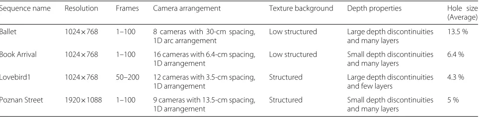
We use four MVD test sequences to evaluate the perfor-mance of the proposed view synthesis method. The test sequences are “Ballet” [40], “Book Arrival” [41], “Love-bird1” [42] and “Poznan Street” [43], which cover various texture and depth characteristics (see Table 2) to vali-date our method in different conditions. The hole size in the table is computed as follows: first, the percentage of hole pixels is calculated for each warped image; then the average of the calculated percentage is computed over the sequence. Note that only the static camera test sequence is used, since the proposed method is limited to static scenes. MVD sequences are used in the evaluation, for the purpose of measuring the quality of the virtual view using full reference objective metrics. We rendered extrapolated virtual views using V+D at the available real camera views, so that rendered views match the ground truth textures in the MVD, as a pre-requisite for measuring full reference quality evaluations.
In the quality evaluations of our proposed method, we use both objective measurements and visual inspection. As the proposed method is aimed at the spatial and tem-poral consistency of the virtual views, we divide the qual-ity evaluation set-up into two parts; spatial consistency evaluation and temporal consistency evaluation.
1. Spatial consistency evaluation 2. Temporal consistency evaluation
Table 2Test input data characteristics
Sequence name Resolution Frames Camera arrangement Texture background Depth properties Hole size (Average)
Ballet 1024×768 1–100 8 cameras with 30-cm spacing, 1D arc arrangement
Low structured Large depth discontinuities and many layers
13.5 %
Book Arrival 1024×768 1–100 16 cameras with 6.4-cm spacing, 1D arrangement
Low structured Small depth discontinuities and many layers
6.4 %
Lovebird1 1024×768 50–200 12 cameras with 3.5-cm spacing, 1D arrangement
Structured Large depth discontinuities and few layers
4.3 %
Poznan Street 1920×1088 1–100 9 cameras with 13.5-cm spacing, 1D arrangement
Structured Small depth discontinuities and many layers
3.1 Spatial consistency evaluation
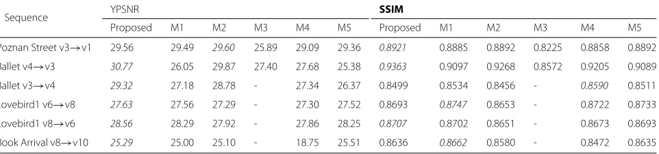
Inpainting is an ill-posed problem, and so investigating the inpainting quality is as complex as the disocclusion problem. Hence, we used the commonly used evalua-tion methodology in the view synthesis context. We use full reference objective metrics peak signal-to-noise ratio of the luminance component (YPSNR) and mean struc-tural similarity index (MSSIM) to evaluate the spatial consistency of virtual views. PSNR measures the absolute difference between images, whereas MSSIM measures structural similarities between images and closely corre-sponds to the perceptual visual quality [44]. In line with commonly used evaluation methodology of view synthe-sis, both metrics are applied on the full image.
3.2 Temporal consistency evaluation
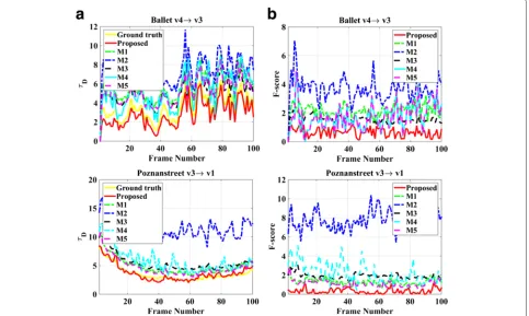
Temporal consistency of the virtual view is evaluated by measuring the amount of flickering. We adopt the method in [45] where the amount of flickering is computed as
τt D=
1
t
p∈t
It(p)−It−1(p),∀t=2. . .Nf (28)
where τDt is the inter-frame average absolute difference at holes in frame t, Nf is the number of frames, tis the number of hole pixels in the framet and the flicker measured between the frames is given as
F-score=τDgt −τDvt (29)
whereτDgt andτDvt represent the inter-frame average abso-lute difference at holes of the ground truth and the virtual view at frame t, respectively. A lower F-score indicates less flickering. Note that flickering is only measured at the inpainted holes.
In addition to the objective spatial and temporal consis-tency measurements, synthesized views are also presented to allow qualitative visual comparison.
3.3 Complexity evaluation
The proposed method is implemented in MATLAB with-out any optimization, which is not the case for reference
methods which are implemented in different platforms. However, few insights about the processing times are given. Note that the main objective is to improve the quality of the rendered view.
We use five of the state-of-the-art methods for compari-son purposes. The comparicompari-son is carried out with various view synthesis methods that use diffusion and exemplar inpainting to fill holes in spatial and temporal domains. MPEG VSRS version 3.5 (M1) is a commonly known view synthesis method, employing several tools to handle artifacts, used to render virtual views [15]. Diffusion-based inpainting is one of the tools used for rendering. Other recent view synthesis methods presented by Ahn et al. [21] and Choi et al. [37] are based on exem-plar inpainting. We denote these methods as M2 and M3, respectively. Method M2 applies inpainting by using only spatial information, whereas M3 applies inpainting by using both spatial and temporal information. More-over, methods M2 and M3 are similar to our inpainting, since M2 and M3 uses exemplar-based inpainting. The remaining two methods are alpha-Gist and VSRS-apha-Etri, which include different hole-filling methods and these methods are developed for view extrapola-tion scenarios [46, 47]. The methods VSRS-alpha-Gist and VSRS-apha-Etri are denoted as M4 and M5, respec-tively. All the state-of-the art methods are used in the traditional scenario, where hole filling is performed after warping to the virtual view. To make a fair compari-son, and since we only have access to the low-resolution results of a few datasets from M3, we downscale the “Ballet” and “Poznan Street” sequence results during comparison.
In the notation used in the article, e.g. v4→v3 indicates that the original camera view 4 is warped to the virtual camera view 3. Parameter values used in the algorithm are empirically selected as follows: optical flow threshold
ρ=0.05 and depth toleranceϑ =10 is used in the sprite construction step. The number of future framesBl =5 is used. Similar to [27], the following parameters are used in the inpainting process: the occlusion thresholdη=5 for a small baseline, a search region of 120×120 pixels, a patch
Table 3Objective spatial quality evaluation
Sequence YPSNR SSIM
Proposed M1 M2 M3 M4 M5 Proposed M1 M2 M3 M4 M5
Poznan Street v3→v1 29.56 29.49 29.60 25.89 29.09 29.36 0.8921 0.8885 0.8892 0.8225 0.8858 0.8892 Ballet v4→v3 30.77 26.05 29.87 27.40 27.68 25.38 0.9363 0.9097 0.9268 0.8572 0.9205 0.9089 Ballet v3→v4 29.32 27.18 28.78 - 27.34 26.37 0.8499 0.8534 0.8456 - 0.8590 0.8511 Lovebird1 v6→v8 27.63 27.56 27.29 - 27.30 27.52 0.8693 0.8747 0.8653 - 0.8722 0.8733 Lovebird1 v8→v6 28.56 28.29 27.92 - 27.86 28.25 0.8707 0.8702 0.8651 - 0.8673 0.8693 Book Arrival v8→v10 25.29 25.00 25.10 - 18.75 25.51 0.8636 0.8662 0.8580 - 0.8472 0.8635
Table 4Objective temporal quality evaluation: average F-score
Sequence F-score
Proposed M1 M2 M3 M4 M5
Poznan Street v3→v1 0.33 1.32 7.78 1.90 2.17 1.11 Ballet v4→v3 0.65 2.19 3.70 1.56 1.74 1.76 Ballet v3→v4 0.54 2.37 4.74 - 1.07 2.13 Lovebird1 v6→v8 0.32 2.72 6.47 - 2.05 2.93 Lovebird1 v8→v6 0.50 2.57 7.58 - 2.17 2.75 Book Arrival v8→v10 0.62 0.33 13.67 - 0.69 1.32
Values in italics indicates the highest score values
size of 11×11 pixels, number of best patchesN = 5, and
β = 3 in (25). The number of occlusion layers identified and inpainted is one.
4 Results and analysis
4.1 Spatial consistency evaluation
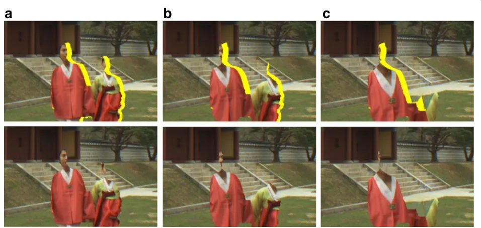
The objective spatial consistency evaluation results are presented in Table 3. Objective measurement results demonstrate that the proposed method performs better than the state-of-the art reference methods. In addi-tion to the objective results, a set of images is shown in Figs. 9, 10, 11 and 12 for visual inspection. As method M1 fills the holes using the structured based
inpainting without boundary classification, results exhibit foreground propagation and blurring artifacts (see row 2 in Figs. 9, 10, 11 and 12). Although method M2 used the background classification while inpainting the holes, holes are still filled with inconsistent background textures due to foreground-background classification (see row 3 in Fig. 9 at the woman’s legs, in Fig. 11 at stairs and in Fig. 12 at wall clock). Method M3 uses the temporal information to fill the holes, however, there are still artifacts: such as the artifacts at the holes near moving objects (see row 4 in Fig. 9 at holes near the woman), the foreground propaga-tion into the holes near moving objects and inconsistent filling at static objects (see row 4 in Fig. 10 at holes near the woman and the pole in front of the car). Methods M4 and M5 are aimed at filling holes in view extrapolation; how-ever, holes are filled with smoothed textures and structure discontinuity (see rows 5 and 6 in Fig. 9, Fig. 10 rows 4 and 5 in Fig. 11 and Fig. 12).
The proposed method results in Figs. 9, 10, 11 and 12 show that holes are filled with spatial consistent back-ground textures when the holes belong to the absolute background. However, the proposed method is limited when it comes to filling the holes when they occur between relative foreground and background. In this case, holes are filled with absolute background textures since the proposed method does not classify the absolute and
a
b
c
relative background. We partially addressed this problem in our previous work by identifying the holes between rel-ative foreground and background but only in the spatial domain [27].
4.2 Temporal consistency evaluation
Results from the objective temporal consistency measure-ments are presented in Table 4. In addition to the average F-score values, the inter-frame absolute difference at the holes and F-score of few frames are presented to show the similarity with the original signal (see Fig. 8). The average flickering score demonstrates that the proposed method performs better than the state-of-the art reference meth-ods (consistent with the results from the spatial domain). Figure 8a shows that the result from the proposed method is similar to the ground truth data. In addition to objec-tive measurements, the visual comparison clearly shows that the holes are temporally stable at the static holes (see row 7 in Fig. 9 at the holes near the man and row 7 in Fig. 10 at the holes near poles and the woman). Holes at the moving objects are also filled smoothly over frames (see row 6 in Fig. 11 at the holes near the woman, the edge of the stairs and in Fig. 12 at the holes near the man). Although flickering artifacts are significantly reduced at both static and moving objects’ holes, apparent flickering is noticeable in the foreground of “Poznan Street” and less apparent in “Book Arrival” sequences due to erroneous depth. However, these are not well reflected by the F-score in the case of “Poznan Street” due to the flickering areas being significantly smaller than other disocclusions in the scène.
4.3 Complexity evaluation
Using the proposed method, it takes about 11 min to ren-der a single frame of “Ballet” v4→v3, whereas using the reference method M1 takes 0.4 min, M2 takes 35 min, M3 takes 5 min, M4 takes 0.12 min and M5 takes 0.05 min, respectively. Note that M1, M3, M4 and M5 are imple-mented in C++, whereas M2 is impleimple-mented in MATLAB. Compared to the spatial hole-filling method M2, the com-putation time for the proposed method is reduced. This is because the holes at the static objects are inpainted once and the inpainted information is reused until they move, which means that there is no need to inpaint every frame for the holes at the dynamic objects. Because of the LDI generation and motion estimation and iterative inpaint-ing, the proposed method is relatively slower than the reference methods.
5 Conclusions
We proposed a new view synthesis method with a spa-tial and temporal consistent layered depth image and depth-based inpainting, in order to improve the rendered view quality. The proposed method handles disocclusions
in the virtual view in a spatial and temporal consis-tent manner. Furthermore, the proposed hole classi-fication using the optical flow ensures the temporal consistency at static object holes by reusing the pre-viously inpainted information. Spatio-temporal consis-tency is also ensured at moving objects’ holes by using the true texture from temporal frames and inpainting. The computational time was reduced compared to ref-erence methods by using the hole classification and reusing the inpainted textures to fill the holes at static objects. Moving weighted average blending between the textures within the hole regions reduced flickering and created a smooth transition. The objective and subjec-tive test results consistently demonstrated that the pro-posed view synthesis method improved virtual view qual-ity of the static background scenes. The results high-light the importance of the hole classification in improv-ing the spatio-temporal consistency of extrapolated views.
The proposed method is aimed at static backgrounds and fills the holes with absolute background only, which means that the method is limited when it comes to han-dling the occlusion between relative foreground and back-ground objects. Investigating possible improvements by identifying the relative foreground and background and building layered sprite is a matter for the future work. Furthermore, if the scene has illumination variations, reusing the inpainted information might cause artifacts. Investigations and finding a way to handle these prob-lems is also a matter for future work. Identifying moving objects using other optimized and dense optical flow algorithms and finding the foreground objects locations in relation to the temporal domain is still challenging and is left for the future work. Optimizing the compu-tation time is another issue to be dealt with in future investigations.
Additional file
Supplementary videos can be found at the paper web page www.miun.se/ stc/Realistic3D/Muddala-2015.
Abbreviations
2D, two-dimensional; 3D, three-dimensional; 3DTV, three-dimensional television; FTV, free viewpoint television; DIBR, depth-image-based rendering; LDI, layered depth image; PSNR, peak signal-to-noise ratio; MSSIM, mean structural similarity index.
Competing interests
The authors declare that they have no competing interests.
Acknowledgements
This work has partly been supported by grant 20120328 of the KK Foundation, Sweden. We would like to thank Sunghwan Choi for providing their test results. We would like to thank Mitra Damghanian and Martin Köppel for their help. We would also like to acknowledge the reviewers for their valuable and helpful suggestions.
References
1. O Schreer, P Kauff, T Sikora,3D Video Communication Algorithms, Concepts and Real-time Systems in Human Centered Communication. (John Wiley& Sons Ltd., Chichester, 2005)
2. M Tanimoto, inComputer Vision and Pattern Recognition Workshop, 2006. CVPRW ’06. Conference On. FTV (free viewpoint television) for 3D scene reproduction and creation, (2006), pp. 172–172.
doi:10.1109/CVPRW.2006.84
3. C Fehn, inProc. SPIE Stereoscopic Displays and Virtual Reality Systems XI. Depth-image-based rendering (DIBR), compression, and transmission for a new approach on 3D-TV, (2004), pp. 93–104. doi:10.1117/12.524762 4. L Zhang, WJ Tam, inIEEE Transactions on Broadcasting. Stereoscopic
image generation based on depth images for 3D TV, (2005), pp. 191–199. doi:10.1109/TBC.2005.846190
5. M Köppel, MB Makhlouf, M Muller, P Ndjiki-Nya, inVisual Communications and Image Processing (VCIP), 2013. Temporally consistent adaptive depth map preprocessing for view synthesis, (2013), pp. 1–6.
doi:10.1109/VCIP.2013.6706436
6. K Muller, A Smolic, K Dix, P Merkle, P Kauff, T Wiegand, View synthesis for advanced 3D video systems. EURASIP J. Image Video Process. (2008). doi:10.1155/2008/438148
7. Y Mori, N Fukushima, T Yendo, T Fujii, M Tanimoto, View generation with 3D warping using depth information for FTV. Signal Process. Image Commun.24(1–2), 65–72 (2009). doi:10.1016/j.image.2008.10.013 8. D Tian, PL Lai, P Lopez, C Gomila, View synthesis techniques for 3D video.
Proc. SPIE.7443, 74430–7443011 (2009). doi:10.1117/12.829372 9. SM Muddala, M Sjöström, R Olsson, S Tourancheau, Edge-aided virtual
view rendering for multiview video plus depth. Proc. SPIE.8650, 86500–865007 (2013). doi:10.1117/12.2004116
10. N Plath, S Knorr, L Goldmann, T Sikora, Adaptive image warping for hole prevention in 3D view synthesis. Image Process. IEEE Trans.22(9), 3420–3432 (2013). doi:10.1109/TIP.2013.2268940
11. N Stefanoski, O Wang, M Lang, P Greisen, S Heinzle, A Smolic, Automatic view synthesis by image-domain-warping. Image Process. IEEE Trans.
22(9), 3329–3341 (2013). doi:10.1109/TIP.2013.2264817
12. SM Muddala, M Sjöström, R Olsson, inInternational Conference on 3D Imaging 2012 (IC3D). Edge-preserving depth-image-based rendering method, (2012). doi:10.1109/IC3D.2012.6615113
13. M Bertalmio, G Sapiro, V Caselles, C Ballester, inProceedings of ACM Conf. Comp. Graphics (SIGGRAPH). Image inpainting, (2000), pp. 417–424. doi:10.1145/344779.344972
14. A Telea, An image inpainting technique based on the fast marching method. J. Graphics GPU Game Tools.9(1), 23–34 (2004). doi:10.1145/344779.344972
15. Report on experimental framework for 3D video coding (2010). ISO/IEC JTC1/SC29/WG11 MPEG2010/N11631. Guangzhou, China
16. KJ Oh, S Yea, YS Ho, inProceedings of the 27th Conference on Picture Coding Symposium, Chicago, IL, USA. Hole filling method using depth based in-painting for view synthesis in free viewpoint television (FTV) and 3D video, (2009), pp. 233–236
17. A Criminisi, P Pérez, K Toyama, Region filling and object removal by exemplar-based image inpainting. IEEE Trans. Image Process.13, 1200–1212 (2004). doi:10.1109/TIP.2004.833105
18. I Daribo, H Saito, A novel inpainting-based layered depth video for 3DTV. Broadcasting IEEE Trans.57(2), 533–541 (2011).
doi:10.1109/TBC.2011.2125110
19. V Jantet, C Guillemot, L Morin, in3D Research. Joint projection filling method for occlusion handling in depth-image-based rendering, (2011). doi:10.1007/3DRes.04(2011)4
20. H Lim, YS Kim, S Lee, O C, JDK Kim, C Kim, inImage Processing (ICIP), 2011 18th IEEE International Conference On. Bi-layer inpainting for novel view synthesis, (2011), pp. 1089–1092. doi:10.1109/ICIP.2011.6115615 21. I Ahn, C Kim, A novel depth-based virtual view synthesis method for free
viewpoint video. Broadcasting, IEEE Trans.59(4), 614–626 (2013). doi:10.1109/TBC.2013.2281658
22. SM Muddala, R Olsson, M Sjöström, Depth-included curvature inpainting for disocclusion filling in view synthesis. Int. J. Adv. Telecommun.6(3 & 4), 132–142 (2013)
23. SM Muddala, M Sjöström, R Olsson, in3DTVConference: The True Vision -Capture, Transmission and Display of 3D Video (3DTV-CON), 2014. Depth-based inpainting for disocclusion filling, (2014), pp. 1–4. doi:10.1109/TBC.2005.846190
24. JW Shade, SJ Gortler, L-W He, R Szelisk, inProceedings of the 25th Annual Conference on Computer Graphics and Interactive Techniques. SIGGRAPH ’98. Layered depth images, (1998), pp. 231–242. doi:10.1145/280814.280882 25. B Barenbrug, R-PM Berretty, RK Gunnewiek, Robust image, depth, and
occlusion generation from uncalibrated stereo. Proc. SPIE 6803, 68031–680318 (2008). doi:10.1117/12.765508
26. B Bartczak, P Vandewalle, O Grau, G Briand, J Fournier, P Kerbiriou, M Murdoch, M Müller, R Goris, R Koch, R van der Vleuten,
Display-independent 3D-TV production and delivery using the layered depth video format. Broadcasting IEEE Trans.57(2), 477–490 (2011). doi:10.1109/TBC.2011.2120790
27. SM Muddala, Free view rendering for 3D video – Edge-aided rendering and depth-based image inpainting (2015). Doctoral Thesis No. 226, Mid Sweden University, Sundsvall, Sweden
28. K-Y Chen, P-K Tsung, P-C Lin, H-J Yang, L-G Chen, in3DTV-Conference: The True Vision - Capture, Transmission and Display of 3D Video (3DTV-CON), 2010. Hybrid motion/depth-oriented inpainting for virtual view synthesis in multiview applications, (2010), pp. 1–4. doi:10.1109/3DTV.2010.5506309 29. RK Gunnewiek, R-PM Berretty, B Barenbrug, JPM aes, Coherent spatial and temporal occlusion generation. Proc. SPIE.7237, 723713–72371310 (2009) 30. M Schmeing, X Jiang, in3DTV-Conference: The True Vision - Capture,
Transmission and Display of 3D Video (3DTV-CON), 2010. Depth image based rendering: a faithful approach for the disocclusion problem, (2010), pp. 1–4. doi:10.1109/3DTV.2010.5506596
31. P Ndjiki-Nya, M Köppel, D Doshkov, H Lakshman, P Merkle, K Muller, T Wiegand, Depth image-based rendering with advanced texture synthesis for 3-D video. Multimedia, IEEE Trans.13(3), 453–465 (2011).
doi:10.1109/TMM.2011.2128862
32. M Köppel, X Wang, D Doshkov, T Wiegand, P Ndjiki-Nya, in19th IEEE International Conference on Image Processing, ICIP, 2012. Depth image-based rendering with spatio-temporally consistent texture synthesis for 3-D video with global motion, (2012), pp. 2713–2716. doi:10.1109/ICIP.2012.6467459
33. W Sun, OC Au, L Xu, Y Li, W Hu, inImage Processing (ICIP), 2012 19th IEEE International Conference On. Novel temporal domain hole filling based on background modeling for view synthesis, (2012), pp. 2721–2724. doi:10.1109/ICIP.2012.6467461
34. C Yao, T Tillo, Y Zhao, J Xiao, H Bai, C Lin, Depth map driven hole filling algorithm exploiting temporal correlation information. Broadcasting, IEEE Trans.60(2), 394–404 (2014). doi:10.1109/TBC.2014.2321671
35. M Xi, L-H Wang, Q-Q Yang, D Li, M Zhang, Depth-image-based rendering with spatial and temporal texture synthesis for 3DTV. EURASIP J. Image Video Process.2013, 1–18 (2013). doi:10.1186/1687-5281-2013-9 36. H-A Hsu, C-K Chiang, S-H Lai, Spatio-temporally consistent view synthesis
from video-plus-depth data with global optimization. Circuits Syst. Video Technol. IEEE Trans.24(1), 74–84 (2014). doi:10.1109/TCSVT.2013.2276699 37. S Choi, B Ham, K Sohn, Space-time hole filling with random walks in view
extrapolation for 3D video. Image Process. IEEE Trans.22(6), 2429–2441 (2013). doi:10.1109/TIP.2013.2251646
38. N Otsu, A threshold selection method from gray level histograms. IEEE Trans. Systems, Man Cybernetics.9, 62–66 (1979).
doi:10.1109/TSMC.1979.4310076
39. BD Lucas, T Kanade, inProceedings of the 7th International Joint Conference on Artificial Intelligence - Volume 2. IJCAI’81, Vancouver, B. C., Canada. An iterative image registration technique with an application to stereo vision, (1981), pp. 674–679
40. CL Zitnick, SB Kang, M Uyttendaele, S Winder, R Szeliski, High-quality video view interpolation using a layered representation. ACM Trans. Graph.23(3), 600–608 (2004)
41. I Feldmann, M Mueller, F Zilly, R Tanger, K Mueller, A Smolic, P Kauff, T Wiegand, HHI test material for 3D video (2008). ISO/IEC JTC1/SC29/WG11 MPEG 2008/M15413
42. GM Um, G Bang, N Hur, J Kim, YS Ho, 3D video test material of outdoor scene (2008). ISO/IEC JTC1/SC29/WG11/M15371
43. M Domanski, T Grajek, K Klimaszewski, M Kurc, O Stankiewicz, J Stankowski, K Wegner, Poznan multiview video test sequences and camera parameters (2009). ISO/IEC JTC1/SC29/WG11 MPEG 2009/M17050. Xian, China
44. Z Wang, AC Bovik, HR Sheikh, EP Simoncelli, Image quality assessment: from error visibility to structural similarity. IEEE Trans. Image Process.
45. M Schmeing, J Xiaoyi, in3DTV Conference: The True Vision - Capture, Transmission and Display of 3D Video (3DTV-CON), 2011. Time-consistency of disocclusion filling algorithms in depth image based rendering, (2011), pp. 1–4. doi:10.1109/3DTV.2011.5877201
46. G Bang, MS Ko, J Yoo, WS Cheong, G Um, N Hur, Boundary noise removal and common hole filling method for VSRS 3.5 (2011). ISO/IEC
JTC1/SC29/WG11 Doc. m19356
47. C Lee, YS Ho, Results of view synthesis using modified hole filling methods (2010). ISO/IEC JTC1/SC29/WG11 Doc. m19281. Guangzhou, China
Submit your manuscript to a
journal and benefi t from:
7Convenient online submission
7Rigorous peer review
7Immediate publication on acceptance
7Open access: articles freely available online
7High visibility within the fi eld
7Retaining the copyright to your article