R E S E A R C H
Open Access
Real-time single-pass connected components
analysis algorithm
Fei Zhao
*, Huan zhang Lu and Zhi yong Zhang
Abstract
Due to the demand for real-time processing in real-time automatic target recognition (RTATR) systems, fast connected components analysis (CCA) is significant to RTATR performance improvement. Conventional single-pass CCA algorithms need horizontal blanking periods to resolve the equivalence, which are difficult to be applied when the streamed data is transmitted without horizontal blanking periods. In this paper, a real-time single-pass CCA algorithm is proposed. Unlike the conventional ones, we adopt the pixel as a scan unit while the line as a labeling unit and manage the correspondence of labels between adjacent rows by designing a multi-layer-index structure. Equivalence is resolved when the image is scanning, without extra processing time. The proposed algorithm is suitable for hardware acceleration, and the streamed image data can be processed during image transmission without horizontal blanking periods. Experimental results indicate that the hardware acceleration of algorithm achieves real-time CCA in RTATR system.
Keywords:Connected components analysis, Real-time processing, Single pass, Hardware acceleration
1 Introduction
Connected components analysis (CCA) is an important step in many machine vision applications. In real-time automatic target recognition (RTATR) systems, such as imaging homing guidance weapon systems, CCA is one of the most fundamental operations, which extracts fea-tures of targets for tracking and recognition. Because of the high-frame rate, which is usually no less than 60 Hz, only about 17 ms are allowed in each frame for all the tasks (such as target detection, tracking, and recog-nition), and less time for fundamental processing. Therefore, fast CCA is significant to the performance improvement in these systems. To date, two main lines of CCA have been followed in general:
(1)Labeling first algorithms [1-5]. These algorithms label the binary image first, and then the features are extracted from the labeled image. The
connected components labeling is a general purpose method, and many researchers have concentrated on the fast connected components labeling. Existing
fast connected components labeling (CCL)
algorithm can be divided into two classes: (a) label-equivalence-based algorithms [1-4] and (b) region-growing-based algorithms [5]. These algorithms process an image in the raster-scan order (top to bottom, left to right) at least twice. In the first scan, provisional labels are assigned, and then the key point is to resolve label equivalence by finding a unique representative label for each group of equivalent labels. In the second scan, the pixel’s provisional label is replaced by the representative label. According to different scan unit, label-equivalence-based algorithms can be divided into run-based algorithms [1], pixel-based algorithms [2,4], and block-based algorithms [3]. Label equivalence is not recorded and resolved in such algorithms, and connected components of any shapes can be labeled in single scan. But these algorithms access the image in an irregular way, which means that the whole image must be available before labeling.
* Correspondence:[email protected]
National Key Laboratory of Automatic Target Recognition (ATR), National University of Defense Technology, Changsha, Hunan, Peoples’Republic of China
Most of the above-mentioned algorithms were designed or improved on general purpose processor (GPP) platform (e.g., PC), and some of them have achieved a good per-formance. For example, algorithms in [1] and [5] offered higher processing speed than others and they only need less than 4 ms to label 512 × 512 binary images on high-performance PC (Intel Pentium D 3.0 GHz + 3.0 GHz CPUs, 2 GB memory, Mandriva Linux OS; Intel Corpor-ation, Sta. Clara, CA, USA) [1]. However, these fast algo-rithms still cannot meet the real-time processing demand in the RTATR systems. This is because the processors’ performance in RTATR system is far poorer than the PC mentioned above when power consumption and volume must be considered. Therefore, studies on algorithms which can be easily accelerated by hardware (e.g., im-plemented on field-programmable gate array, FPGA) be-come a feasible way to figure out real-time problem. Crookes, Benkrid, et al. have implemented a resource-efficient multi-pass algorithm on FPGA [6], but indeter-minate number of passes is required to complete the labeling. Jablonski and Gorgon [7] have implemented the classic two-pass connected components labeling on FPGA, but the method requires a second pass, and two-clock cycles per pixel plus a small overhead for region merging. Kofi et al. have presented a run-length-based connected component algorithm for FPGA implementa-tion [8,9], runs in images are extracted and initially labeled in the first pass, then equivalence sets are resolved, and runs are translated to connected components. However, the equivalence resolution is still sequential and requires that all runs are initially labeled at first. Clearly, it is un-suitable for real-time processing of streamed image data.
(2)Single-pass CCA algorithms [10-12]. D.G. Baily et al. have proposed another CCA method, in a more goal-directed way: Single-pass CCA algorithm, which accumulates the feature data (such as the area, center of gravity, and perimeter) while the pixels are being scanned and labeled, does not generate a labeled image. Essentially, the single-pass CCA algorithms are label-equivalence-based too, which resolve equivalence in each row during the horizontal blanking periods as well as merge accumulated data. These algorithms eliminate the need for producing a labeled image and spare the second re-labeling pass, hence suitable for processing streamed image data on FPGA. Furthermore, an optimized single-pass CCA algorithm [12] is proposed, which applies a label recycling scheme between adjacent rows to save the memory resources. Such methods will be of great benefit to the RTATR systems: streamed images can be processed in the transmission from detector to processing unit and this will save the processing
time and shorten the delays of closed-loop control. However, these methods require horizontal blanking periods to resolve equivalence, which will be a bottleneck when the streamed data is transmitted without horizontal blanking periods.
In this study, we present a new single-pass CCA al-gorithm, which eliminates the requirement for hori-zontal blanking periods in aforementioned methods, and the FPGA implementation of proposed algorithm which achieves real-time processing for streamed im-ages. The remainder of this paper is organized as fol-lows. Section 2 presents the principle of the algorithm. In Section 3, the hardware implementation of the pro-posed method is introduced. Section 4 gives the ex-periment results of the algorithm in both PC and RTATR platforms, and the comparison with existing single-pass CCA algorithm is presented, too. Section 5 concludes the discussion.
2 Proposed algorithm
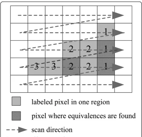
Classical label-equivalence-based algorithms set pixel as a scan unit, so redundant labels and label equivalence will be generated for stair-like connected components. As shown in Figure 1 (assuming four-connectivity), the pixels belonging to the same region are labeled with different numbers, and more label equivalence will be encountered while the image is being scanned (the shadowed squares represent the pixels at which label equivalence is encountered). It also means that more
resources are needed for equivalence resolving. Run-based algorithms can solve the problem, and runs ex-traction is necessary in such algorithm. When a run is extracted, connectivity of runs between adjacent rows is detected, and label equivalence is recorded and re-solved. In other words, few operations are needed be-fore a run is extracted, and most operations are gathered at the end of a run. Centralized operations be-come the bottleneck of hardware acceleration.
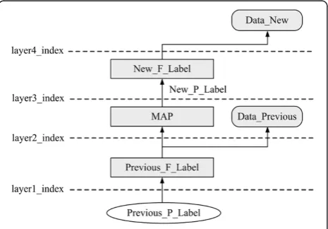
In this paper, we combine the advantages of pixel-based and run-pixel-based algorithms, adopt pixel as a scan unit and run as a labeling unit. That means we scan the image pixel by pixel without labeling, and the labels are assigned for the runs. Therefore, redundant labels and equivalence shown in Figure 1 are avoided, the opera-tions are distributed to each pixel, and only run labels assigned in the previous row are concerned in labeling and equivalence. In addition, a multi-layer-index struc-ture is designed to manage the correspondence between labels in the previous row and labels in the current row. The structure of multi-layer-index is shown in Figure 2.
As shown in Figure 2, Previous_P_Label and New_P_
Label are provisional labels assigned in the previous row and the current row;Previous_F_Labeland New_F_Label
are label-index tables, which indicate the representative
labels corresponding to Previous_P_Label and New_P_
Label. For instance, ifPrevious_F_Label(p)= n, it indicates that the representative label for pis n, in which pand n
are labels assigned in the previous row; ifPrevious_F_Label
(p) = 0, it indicates that the representative label for pis
itself, and New_F_Label has the same meaning in the
current row. MAP is the translation table, which denotes the correspondence between the representative labels in the previous row and the provisional labels in the current
row. If MAP(i) = k, it indicates that i which is a repre-sentative label in the previous row has been translated to labelkin the current row; if MAP(i)=0, it indicates that representative label i in the previous row does not have a translated label in the current row. The feature data ta-bles which store the accumulated features are presented as Data_Previous and Data_New and the four layer in-dexes (shown aslayer1_index,layer2_index,layer3_index, and layer4_index in Figure 2) form a pipeline when a provisional label in the previous row is indexed.
In our method, the key point is to keep the consistency of multi-layer-index between adjacent rows, which means the correctness of correspondence(such as correspondence between labels in adjacent rows, corres-pondence between feature data in adjacent rows, and correspondence between feature data and labels in the same row) must be kept in the scanning. By setting the run as labeling unit, only the labels in the previous row are concerned in the scanning. Thus, the assignment of provisional labels in the current row is simplified, and only in some special cases (such as overlapping between runs in adjacent rows, label equivalence and tail of runs) does the multi-layer-index structure need to be updated. Furthermore, the updating can be distributed into each layer of multi-layer-index (fromlayer1_index
to layer4_index), and the operations in each layer can be accomplished independently while the pixel is in scanning. By doing this, all the special cases can be re-solved in the scanning, eliminating the need for hori-zontal blanking periods. In the scanning of pixels, the feature data are accumulated and labels are assigned to the runs, the multi-layer-index is updated in some spe-cial cases to keep the consistency, and the features of completed connected components are passed to subse-quent processing unit. In this study, the proposed algo-rithm is divided into two blocks for introduction: (1) special case detection and feature accumulation and (2) multi-layer-index update.
2.1 Special case detection and feature accumulation In the pixel-based scan process, the run is set as label-ing unit, which means we must detect the beginnlabel-ing of the run at first and accumulate the features before the tail of the run. When the scanning pixel lies inside the run, overlapping between runs in adjacent rows and label equivalence in the previous row are detected, and some details (presented as overlapping modes and equivalence modes) about the special cases are pro-vided for the updating. When the scanning pixel is the tail of the run, the run which is just scanned will be la-beled by a provisional label, and some details about the run (such as run end modes) will be sent to the updat-ing module, too.
To detect the overlapping of runs in the pixel-based scan, the relations between scanned pixels and runs in the current row need to be detected first. For a binary image, suppose that the current scanning pixel isP(y,x),
y andxare row and column. The information of pixels in the previous row (y − 1) is stored as info(x) = {run_start,g,label}, in whichxis column;run_start= 1 indicates thatP(y−1,x) is the head of a run,g= 1 indi-cates thatP(y−1,x) is nonzero,labelis the provisional label of run which containsP(y − 1,x). WhenP(y,x) is scanned, the relation between P(y,x) and runs is ex-tracted as follows:
(1)IfP(y,x−1) = 0 andP(y,x)≠0, thenP(y,x) is the beginning of a run.
(2)IfP(y,x−1)≠0 and (y,x)≠0, thenP(y,x) exists inside a run.
(3)IfP(y,x−1)≠0 andP(y,x) = 0, thenP(y,x) is the first pixel behind the tail of a run.
(4)IfP(y,x−1) = 0 andP(y,x) = 0, thenP(y,x) does not exist inside the run.
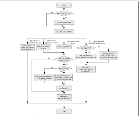
In this paper, we take four-connectivity as example to detect the connectivity between adjacent rows. The whole flow of special case detection and label assign-ment is shown in Figure 3, in which overlapped is the flag of overlapping between runs in adjacent rows; when
overlapped= 1, it indicates the run which containsP(y,x) is connected with the run labeled as last_label in the previous row; pfl1 = last_label if Previous_F_Label(last_
label) = 0, else pfl1 = Previous_F_Label(last_label);new_
cnt indicates the assigned new provisional label in the current row.
As shown in Figure 3, when the image is scanned, the label in the previous row is stored in last_label and equivalence decision is performed. When P(y,x) is the beginning of the run or inside a run, the connectivity is detected by judging info(x).g. If the connectivity is detected (overlapped= 1), the translated label (the label which corresponds topfl1 in the current row (i.e., MAP (pfl1)) when MAP(pfl1) ≠ 0, or new_cnt when MAP (pfl1) = 0) is stored inline_new_cnt, and it is used to as-sign provisional label for the run when the first pixel be-hind the tail of the run is encountered, theline_new_cnt
is also used for updating of the multi-layer-index struc-ture. The overlapping mode (overlapping_mode) and run end mode (run_end_mode) are also recorded for the updating of the multi-layer-index structure. In the scan-ning, updating of info(x).g and info(x).run_start is per-formed at each pixel, and assignment of info(x).label is performed at the tail of the run.
By setting the run as labeling unit, the equivalence is detected between two provisional labels which are assigned in the previous row. As shown in Figure 3, equivalence decision is performed when the beginning of the run in the previous row is found: whenP(y,x)≠0 and info(x).run_start = 1, if overlapped = 1, it indicates thatlast_labelandinfo(x).labelare equivalent. Suppose
Depending on the different results of layer2_index for
last_labelandinfo(x).label(i.e., different provisional labels in the current row which correspond to last_label and
info(x).label), two different equivalence modes (shown as
equ_mode= 1 andequ_mode= 2 in Figure 4) may exist, which are important for multi-layer-index updating.
For analysis of the features of the region, such as the area, center of gravity, bounding box, or perimeter, some features should be collected when each pixel is scanned. When position of P(y,x) is judged, the data can be accu-mulated from the beginning to the tail of the run, and the accumulated data can be used for updating of data table.
2.2 Multi-layer-index update
Depending on different modes of special cases (such as overlapping between runs in adjacent rows, equivalence and run end), the multi-layer-index structure should be updated during the scanning to maintain the correct-ness of index results in each layer.
2.2.1 Overlapping between runs in adjacent rows
To save the resources for labels storing, labels are reused between adjacent rows. When the scanning pixel P(y,x) connects with runLp in the previous row, it means that
the connected component which contains Lp is not
complete, label assigned forLpin the previous row should
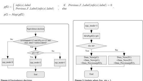
pfl2¼ info xð Þ:label
Previous F Label info xð ð Þ:labelÞ
; if Previous F Label info xð ð Þ:labelÞ ¼0
; else :
pl2¼Mapðpfl2Þ
be translated to a new label, and the translation table MAP needs to be updated.
When it is the first time to setoverlapped= 1 and MAP (pfl1) = 0 (as shown in Figure 3) (which means Lp
con-nects with no pixels before, corresponding tooverlapping_
mode= 1), a new label in the current row is assigned and the translation table MAP is updated as MAP(pfl1) =
line_new_cnt;line_new_cntis the assigned new label which is recorded in Figure 3. The feature data is translated as
Data_New(line_new_cnt)= Previous(pfl1). If it is not the first time to findoverlapped= 1 (i.e., MAP(last_label)≠0 corre-sponding tooverlapping_mode= 0), no update is required.
2.2.2 Equivalence
As described before when P(y,x) ≠ 0 and info(x).
line_start= 1 and ifoverlap= 1, it indicates thatlast_label
and info(x).label are equivalent. Suppose thatpl1 = Map
(pfl1), fl1 = New_F_Label(pl1), and New_F_Label(pl2) =
fl2. As shown in Figure 4, there are two different equiva-lence modes depending onpl2. When the equivalence is encountered, the translation table, label-index table, and data table in the multi-layer-index should be updated to keep the consistency. When equ_mode= 1, the update is shown in Figure 5. When equ_mode = 2, the update is shown in Figure 6.
2.2.3 Run end
When P(y,x) is found at the first pixel behind the tail of the run, the data table needs to be updated with accumu-lated feature data of the run. Assume the accumuaccumu-lated fea-ture data are denoted asD_line, whenrun_end_mode= 1, that is, the run just scanned does not connect to any runs in the previous row, Data_new(new_cnt) = D_line. If
run_end_mode= 2, the updating is different according to
fl1, as it is shown in Figure 7.
After the above-mentioned update, the multi-layer-index and data table are kept up to date. The update is carried out as soon as the pixel is scanned, and no extra periods are required.
When the last pixel in the current row is scanned,
Previous_F_Label is replaced with New_F_Label, and the
Data_Previousis replaced withData_Newfor the updating in the next row. By analyzing the translation table MAP and the previous data table Data_Previous, connected components which are completed can be found so the fea-ture data can be passed to the next processing unit imme-diately, without waiting for the end of image scanning. At the end of image, a dummy row is needed for analyzing the last row in the image and initializing the memories.
3 Hardware acceleration design
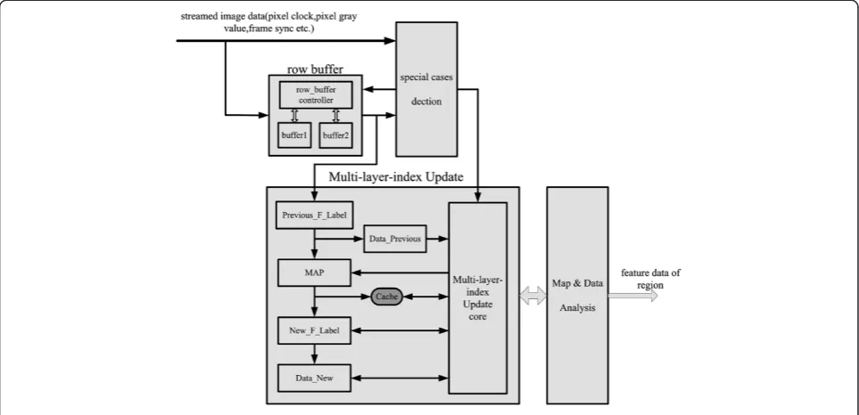
According to the principle of proposed algorithm, the algorithm can be divided into two main blocks: (1) spe-cial cases detection and data accumulation and (2) multi-layer-index update. In the first block, the opera-tions depending on the different posiopera-tions of the scan-ning pixel can be processed in parallel. Meanwhile, the index and update of multi-layer-index can be accom-plished by pipelining, and operations in each level of pipeline can be executed in parallel depending on the different modes (such as different equivalence modes, run end modes and overlapping modes). The proposed algorithm is implemented on Xilinx XC2V3000-6FG676
FPGA, and the architecture of hardware implementation is shown in Figure 8. As shown in Figure 8, the hardware implementation of proposed algorithm can be divided into four main blocks:
1. The row buffer block is used to store the pixel information in the previous row. It is implemented by dual-port block RAM (BRAM). Considering that the information updating of scanning pixel will conflict with the provisional label assignment at the tail of the run, two BRAMs are used alternately to store pixel information in each row.
2. The special cases detection and data accumulation block provide different flags for multi-layer-index updating; meanwhile, the feature data are also accumulated.
3. Multi-layer-index update block updates the translation table, label-index tables, and data tables, and
maintains the correctness of index results in each layer. In this block, the label-index tables (such as Previous_F_LabelandNew_F_Label) are implemented by register array; translation tableMAPand data tables (such asData_Previous,Data_New) are implemented by dual-port Block RAMs.
4. MAP and data analysis block analyze the translation table MAP and the data tableData_Previousin the scanning, then output the feature data of connected components if they are found complete.
In the implementation, three data tables, two transla-tion tables, and two label-index tables are used in turn to achieve real-time update and analysis. We assume d1, d2, and d3 are three identical data tables, m1 and m2 are two identical translation tables, and i1 and i2 are two identical label-index tables before the image is scanned, they are all initialized to 0. In the first row of image, d1 and d2 are used as Data_Previous and Data_New, m1 is used as MAP, i1 is used asPrevious_F_Label, and i2 is used as New_F_Label. At the end of the first row, d2 is used as Data_Previousand d3 is used asData_New, m2 is used as MAP, and m1 and d1 are replaced and used to extract the feature data of regions if the regions are found complete. Meanwhile, the i1 is initialized to 0 and exchanged for i2, so i2 becomes thePrevious_F_Labeland i1 becomes the New_F_Label in the second row. At the end of each row, the tables exchange alternately, and the analysis for completed connected components and updat-ing of multi-layer-index can be processed in parallel.
to the frequency of pixel clock and equals to the trans-mission period of images.
4 Experiment results
As aforementioned, the proposed algorithm not only runs on GPP platform, but also suits hardware acceleration in FPGA-based RTATR platform. Therefore, we verified the performance in both PC and RTATR platforms. The algo-rithm in [5], as an acknowledged fast connected compo-nents labeling algorithm, is selected for comparison; and running time is the key measurement in the experiment. For a more special purpose, the optimized single pass [12] algorithm which is designed for hardware implementation is also selected for comparison, and the resource utili-zation and processing ability are analyzed.
4.1 Experiment in different platforms
In the experiment, the two platforms are PC (2.5 GHz + 2.5 GHz, 2G memory, Windows XP OS, VC6) and our RTATR (digital signal processor, DSP: TMS320C67 13,200 MHz + FPGA: XC2V3000-4FG676) system. In the RTATR system, selection of processor (DSP) is limited because of the volume and power consumption constraints, the fre-quency of the processor is only 200 MHz, and the external bus bandwidth is ideally 400 MB/s. For processor-based algorithms (like algorithm in [5]), the image can only be processed after the transmission, and the access of image data from external memory becomes the bottleneck of processing. Algorithm in [5] is performed by adding an analysis step after the CCL in the experiment. By contrast, the proposed algorithm can be implemented by FPGA in the transmission of image.
Many images have been chosen for experiment. Some of the images were acquired by the long wave infrared (IR) detector (MARS LW K508; Sofradir Company, Chatenay, Malabry, France) and without loss of generality, the others are downloaded from SIPI Image Database [13]; all the ex-periment images are converted to 256 × 256 binary images in advance. In this paper, six representative images with different connectivity complexities are selected for discus-sion. They are illustrated in Figure 9, in which panels a, b, and c are acquired from the IR detector and panels d, e, and f are downloaded from the SIDBA. As shown in Figure 9, more and more connected components and equivalence occur in the Figure 9a,b,c,d,e,f. Therefore, dif-ferent processing resources (e.g., buffers and processing time) are required for these images. In the comparison be-tween the proposed algorithm and the algorithm in [5], we take these images as examples to verify the running time on different connectivity complexity condition. In the PC system, the images are loaded into the memory and then the two algorithms are performed. In RTATR system, a dedicated PCI card is used to send images to RTATR sys-tem, as same as the IR detector; the streamed data consist of image data, pixel clock, and frame synchronization sig-nal; the frequency of pixel clock is 15 MHz, and the frame rate is 100 Hz.
image is being transmitted in a raster-scan order; the pro-cessing time is a fixed value, and it is the transmission period 256256
15106 ≈4:37 ms
. By contrast, the algorithm in
[5] can only process the stored image by DSP when the
transmitting is over, so the time consumption is relevant to the complexity of image and exceeds the frame period (10 ms) in all the cases. This means that the algorithm is not suitable for such a RTATR platform. By accelerating the proposed algorithm on FPGA, about 5.6 ms is left for other algorithms after the transmission of streamed image, and real-time processing in RTATR platform is realizable.
4.2 Hardware acceleration comparison
In the implementation of proposed algorithm, the length of row buffers is the same size as the number of
col-umns; in the extreme situation, there will be M/2
provisional labels in a row, which means that the length of the data tables, translation tables, and label-index ta-bles is M/2. In this study, the hardware acceleration of proposed algorithm is used for analyzing the area, sum of columns, and sum of rows of pixels in each connected component and therefore, the center of each region will be obtained. Suppose the images are acquired by the aforementioned IR detector, the size of image is 256 × 256, and the streamed image data consist of 14 bits gray data, 1 bit frame synchronization, and 1 bit pixel clock, which are transmitted in raster-scan order without hori-zontal blanking periods. The resources and the best timing performance of pixel clock in FPGA XC2V3000-4FG676 are shown in Table 2, and the resources used in [12] is presented, too. The percentage of resources utilization of proposed algorithm is also shown in the bracket.
Comparing with existing single-pass CCA algorithm (such as hardware-implemented algorithm in [12]), our goal is to obtain the center of region, and implementation in [12] only aims at the area, therefore, the used BRAM is much more than [12]. Considering the image size is larger in [12], the occupied resource in our implementation is much more than in [12]. This is because the multi-layer-index structure and row buffer occupy more RAM and registers to store intermediate results, and more logical judgments in the indexing and updating of multi-layer-index cause more occupation of LUTs. However, the contribution of this paper is that the need of horizontal blanking periods has been eliminated for equivalence reso-lution. From this point of view, the consumption in our application is acceptable. By performing the CCA in the scanning, the center of each region is obtained when the
Table 1 Experiment results
Image CCa Time consumption of proposed algorithm (ms)
Time consumption of algorithm in [5] (ms)
PC RTATR PC RTATR
a 5 2.34 4.37 0.32 22.7
b 67 2.81 4.37 0.34 30.4
c 134 2.79 4.37 0.33 33.7
d 220 2.75 4.37 0.46 37.8
e 341 3.22 4.37 0.91 62.7
f 802 3.33 4.37 0.82 73.2
a
Number of connected components.
Table 2 Resource utilization
Resource Proposed
method
Algorithm in [12]
Used BRAMs 13 (14%) 4
Used slice flip-flops 3,154 (11%) 600
Used four-input LUTs 4,587 (16%) 1,757
Maximum clock frequency (MHz) 95.7 40.63
LUTs, look-up tables. Figure 9Experiment images.(a) Cone target, (b) two persons in
scanning is over. This is very important for real-time pro-cessing in systems without blanking periods (such as the IR detector in our system).
Furthermore, the maximum clock frequency of the de-sign exceeds 90 MHz which is more than twice the fre-quency which can be gotten in [12]. If the pixel clock frequency is higher (must lower than 90 MHz), the hard-ware implementation of the proposed algorithm will consume less time, and real-time CCA can be realized for larger size images.
5 Conclusions
In this study, a real-time single-pass connected compo-nents analysis algorithm is proposed. Compared with the existing single-pass CCA algorithms, the pixel is set as a scan unit, the run is set as a labeling unit, and the corres-pondence of labels in adjacent rows are managed by the multi-layer-index structure. By doing this, the equivalence can be resolved as soon as it is encountered, eliminating the need for waiting for the end of the row. Due to the preferable architecture, the algorithm can perform single-pass CCA on FPGA while the pixel is being transmitted. Experimental results indicated that the algorithm is suit-able for real-time processing in the RTATR system.
Competing interests
The authors declare that they have no competing interests.
Received: 20 March 2012 Accepted: 27 March 2013 Published: 22 April 2013
References
1. H Lifeng, C Yuyan, S Kenji, A run-based two-scan labelling algorithm. IEEE. Trans. Image. Process.17, 749–756 (2008)
2. H Lifeng, C Yuyan, S Kenji, An efficient first-scan method for label-equivalence-based labelling algorithms. Pattern. Recognit. Lett. 31, 28–35 (2010)
3. G Costantino, B Daniele, C Rita, Fast block based connected component labelling, inIEEE International Conference on Image Process (ICIP2009) (Grant Hyatt Cairo, Cairo, Grant Hyatt Cairo, Cairo, 7–10 November 2009), pp. 4061–4064
4. S Luigi Di, B Andrea, A simple and efficient connected components labelling algorithm, inInternational Conference on Image Analysis and Process (Venice, 27–29 September 1999), pp. 322–327
5. C Fu, C Chun-Jen, L Chi-Jen, A linear-time component-labelling algorithm using contour tracing technique. Comput. Vis. Image. Und.93, 206–220 (2004)
6. D Crookes, K Benkrid, FPGA implementation of image component labelling,
inProceedings SPIE 3844, Reconfigurable Technology: FPGAs for Computing
and Applications(Boston, 20–21 September 1999), pp. 17–23
7. M Jablonski, M Gorgon, Handel-C implementation of classical component labelling algorithm, inEuromicro Symposium on Digital System Design
(DSD 2004)(Rennes, 31 August to 3 September 2004), pp. 387–393
8. A Kofi, H Andrew, D Patrick, O Jonathan, A run-length based connected component algorithm for FPGA implementation, inInternational Conference
on Field-Programmable Technology(Taibei, 8–10 December 2008),
pp. 177–184
9. A Kofi, H Andrew, D Patrick, M Hongying, Accelerated hardware video object segmentation: from foreground detection to connected components labelling. Comput. Vision. Image. Und.114, 1282–1291 (2010)
10. DG Bailey, CT Johnston, Single pass connected components analysis, in
Proceedings of Image and Vision Computing(University of Waikato, Hamilton,
5–7 December 2007), pp. 282–287
11. CT Johnston, DG Bailey, FPGA implementation of a single pass connected components algorithm, inThe 4th IEEE International Symposium on Electronic Design, Test and Applications (DELTA 2008)(Hong Kong, 23–25 January 2008), pp. 228–231
12. M Ni, DG Bailey, CT Johnston, Optimised single pass connected components analysis, Taibei, inInternational Conference on
Field-Programmable Technology(Taibei, 8–10 December 2008), pp. 185–192
13. University of Southern California,SIPI Image Database. http://sipi.usc.edu/ database/database.php?volume=misc&image=11#top, Accessed June 2010
doi:10.1186/1687-5281-2013-21
Cite this article as:Zhaoet al.:Real-time single-pass connected components analysis algorithm.EURASIP Journal on Image and Video Processing20132013:21.
Submit your manuscript to a
journal and benefi t from:
7Convenient online submission
7Rigorous peer review
7Immediate publication on acceptance
7Open access: articles freely available online 7High visibility within the fi eld
7Retaining the copyright to your article