R E S E A R C H A R T I C L E
Open Access
Development of 3D viewer based
teleoperation interface for Human Support
Robot HSR
Hiroaki Yaguchi
1*, Kenji Sato
1, Mitsuharu Kojima
1, Kiyohiro Sogen
2, Yutaka Takaoka
2,
Masayoshi Tsuchinaga
2, Takashi Yamamoto
2and Masayuki Inaba
1Abstract
In this paper, we introduce 3D-viewer-based teleoperation system for manipulation task of Human Support Robot HSR. The system is integrated by three functions; 3D environment information visualization based on Manhattan-world assumption, known object recognition using LINE-MOD algorithm, and virtual teaching with 3D robot model using interactive marker. We show some experimental results of manipulation tasks using proposed system.
Keywords: Home robot; Service robot; Teleoperion
Background
In Japan, population aging of society is estimated to progress faster than foreign countries, corresponding to shortage of labor and caregiver is a very serious prob-lem. Also encouraging self-reliance support of elderly and handicapped persons is a very important problem to improve in a viewpoint of quality of life. To solve this prob-lem, we are developing safety, small, wide working area, high functional Human Support Robot: HSR for elderly or handicapped person and their family or caregiver.
We also take operation test in house environment of the handicapped person, and evaluate object pickup task using tablet-based HMI: Human Machine Interface to correspond to the needs of “object handling with teleop-eration” [1]. According to this operational test, we found problems of teleoperation HMI as follows;
I) It is difficult to estimate distance to target object or space between robot and environment.
II) The consumer needs to use not custom-made shelf for robots with visual marker but normal shelf. III) In object manipulation task, it is difficult to move a
hand to target position correctly.
*Correspondence: [email protected]
1Department of Information Science and Technology, The University of Tokyo, 7-3-1 Hongo Bunkyo-ku, Tokyo, Japan
Full list of author information is available at the end of the article
For teleoperation HMI, following functions are necessary;
I) Wide-view environment information representation around robot and grasp target object
II) Known object recognition without visual marker III) Robot operation HMI easy to understand robot
status and to operate.
To realize these functions, we developed about 3D face set representation of environment converting from point clouds obtained 3D camera, robust and markerless known object recognition using Improved LINE-MOD, and motion teaching method to 3D robot model using interactive markers.
In this paper, we developed a novel teleoperation inter-face showing robot status, surrounding environment, and detected known objects on 3D viewer. We also con-structed teleoperating/motion teaching system by operat-ing 3D robot model on developped 3D viewer.
HSR: Human Support Robot and teleoperation system
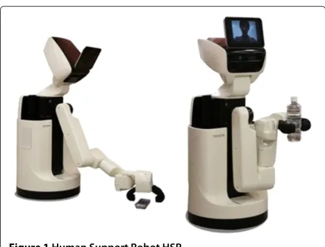
Human Support Robot HSR (Figure 1) is developed as small, light-weight, and safety mobile manipulator robot for the daily life environment, its footprint is 370 [mm] diameters, it has a retractable 7DoF single arm and an extensible body (having 1 DoF, slides by z axis), unholo-nomic differential 2 wheels base, and it also has a 3D
Figure 1Human Support Robot HSR.
camera and high resolution stereo cameras, and tablet on the Head. Head mounted tablet shows movie and audio of operator, like telepresens robot. High resolution camera is used to detect AR marker, the robot mainly measures external information from 3D camera as 640×480 colored point cloud.
In operation tests of object handling task is realized by combination of following 3 functions; Environment information representation using robot mounted camera image, Known object recognition using 2D visual marker, and Dialog based teleoperation user interface. Figure 2 shows a robot controller of dialog based HMI. This HMI supposes operation using the touch panel, surrounding environment of the robot is shown using head mounted camera image, robot action is selected from buttons on the right side of the screen, for each action different oper-ation interface is called. Object recognition is realized by putting 2D visual markers on the environment. Prob-lems of this system are following 3 points; 1) Using only 2D color image obtained from 3D camera, it is difficult to understand the environments around robot because it has a narrower viewing than human’s, and sometimes occlusion is occurred by the robot’s own body. 2) Object recognition using 2D visual marker limits usable objects from robots. It needs the initial cost to put markers on the environment, it also may be difficult to recognize mark-ers due to size of markmark-ers, and distance from the robot, and sometimes objects can not be put markers. 3) Dia-log based user interface can call only predefined tasks and cannot adjust detailed robot motions from the interface.
Especially, in unknown real environment, it is very dif-ficult to sense, plan, and act autonomously, so sometimes the direct operation of robot can be the most realis-tic and fastest way to achieve tasks. We also consider to operate structured object, such as furniture or doors, as a higher level task. In related works, Chitta et al. [2] achieved autonomous door opening task of PR2 using
pull, and revolve [4]. Operation type and amount are instructed directly on input image from camera. Azuma’s system can operate various structured objects with simple solution, however, this can not reuse instructed opera-tion. Yamazaki et al. [5] proposed a method which can add manipulable object through creating models from tex-ture and shape information measured by external sensors. Yamazaki defined the drawer opening task by the robot as combination of following sub tasks.
i) Teaching knowledge that is necessary to operate the object.
ii) Adding ID tags or artificial markers to target object. iii) Teaching how to operate via teleoperation or direct
teaching.
According to Yamazaki’s approach, robots can operate furniture when it has following 3 abilities;
i) Human can estimate necessary knowledge to operate from environment information.
ii) The robot can recognize a target object autonomously.
iii) The robot can be teleoperated.
These factors are consistent with problems of HMI described in the introduction.
We propose following 3 functions;
Light-weight and easy to understand environment information representation and storing.
Robust recognition and pose estimation of known objects.
Direct operating and motion teaching using 3D interactive robot model
In this paper, we develop the user interface that can show robot pose and surrounding environment simulta-neously by representing environment, object, and robot information on 3D viewer to teleoperate Human Support Robot HSR combining 3 functions.
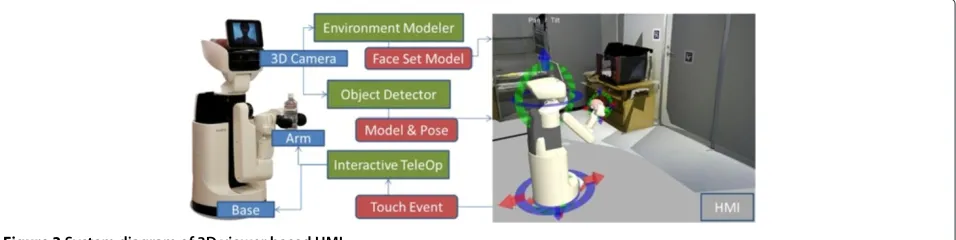
Figure 2Human interface using dialog-based HMI.
camera, and display 3D environment and object model information on 3D viewer. Interactive teleoperator can control robot via 3D model displayed on 3D viewer. We also achieve the door opening task and the object pick-up task by teleoperation using the system.
Methods
3D environment reconstruction and representation
To realize a useful human machine interface, we propose the method to translate from 3D point cloud to orthog-onal face set to show 3D environment information as lightweight and easy to understand representation on the 3D viewer.
We consider to employ 3D reconstruction method like Visual SLAM to show 3D environment information. RGBDSLAM [6] and KinectFusion [7] are popular visual SLAM method using 3D camera. In RGBDSLAM, envi-ronmental information is stored as dense point cloud using key frames of input images. KinectFusion [7] stores environment information as infinite 3d voxel. However these representation does not have enough shape features.
Indoor room environment has a feature that is con-structed combination of orthogonal planes each other, like floor, ceiling and walls. This assumption about struc-ture of indoor environment is called Manhattan-world assumption. Using this shape assumption, easy to under-stand environment information representation can be realized. Furukawa et al. [8] used this assumption to reconstruct and estimate structure of building using pho-tograph database. Yaguchi et al. [9] applied this assump-tion to 3D camera and proposed the fast and lightweight method to construct 3D environment model of the room. In this paper we represent environment information using [9].
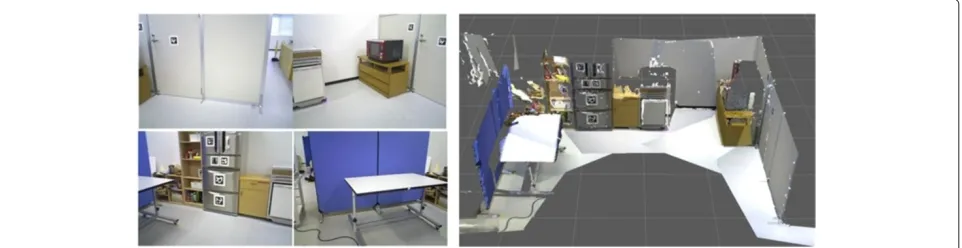
Figure 4 shows the face set model of room environ-ment reconstructed from plural 3D images. 4 images in the left column are part of the images used for reconstruction, and an image in the right column is a reconstructed 3D model. The proposed system can rep-resent a wide view 3D environment information with expanding viewing by combining face set of plural 3D images.
Figure 43D environment model based on Manhattan-world assumption.
Figure 5Sequence of 3D environment modeling.
Figure 6Image of face set and rest points.
Table 1 Results of plane detection; Comparison distance between 2 planes
Estimated [mm] Ground Truth [mm]
Microwave - Wall (1) 517 500
Dashboard - Floor (1) 439 430
Microwave - Wall (2) 511 500
Dashboard - Floor (2) 433 430
Figure 5 shows the sequence of the proposed method. At first, orthogonal 3 dominant axis are estimated from distribution of the normal vectors of input point cloud and all points are segmented to 3 groups associated with dominant axis. The next plane position is estimated from distribution of position of points by direction of the asso-ciated dominant axis applying peak estimation. Bar graphs in the right side of Figure 5 shows histograms of points distribution. In this situation, red points have 3 peaks i.e. there are 3 planes in the red dominant axes, and the green and the blue axis have 2 and 1 plane(s) respectively. At last, face shape is estimated from associated points for each plane. The proposed method can translate from point cloud to orthogonal face set.
On the other hand, points not assigned to any planes are obtained as a result. Each points are checked by normal vector direction and distance from the nearest plane. When a point hasdifferent directed normal from dominantaxis oris far from any planes, it is considered
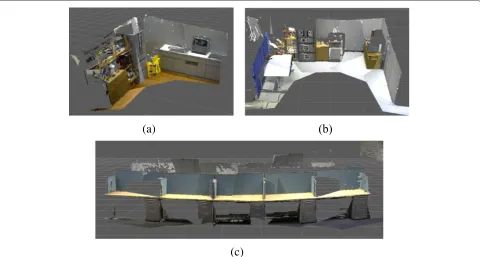
Table 2 Specification of 3d environment models
(a) (b) (c)
Input points size (ave.) [kB] 12800 12800 12800
Face set size (ave.) [kB] 934 349 519
Texture image size (ave.) [kB] 83.3 81.8 79.7
Rest points size (ave.) [kB] 1697 1462 881
compression rate [%] 21.2 14.8 11.6
Input points num 307200 307200 307200
Rest points num (ave.) 26115 22381 13631
Rejected rate [%] 8.50 7.29 4.44
to violates the assumption. These points considered to represent details violating the assumption, so added to the model as a point cloud, as shown in Figure 6. In this figure, a shelf is represented as face set because its shape ful-fills Manhattan-world assumption, on the other hand, a pot is represented as points because its shape violates the assumption.
Evaluation
We evaluated the proposed method in [9]. Firstly, we evaluate the accuracy of plane estimation with the input images shown in Figure 7. Table 1 shows the result. In this evaluation, we compared distances between pairs of planes. Errors in plane estimation are less than 20 [mm] at about 2 [m] distance for all planes. We also evalu-ated about amount of model files using dataset shown in
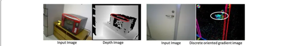
Figure 9Known object detection using LINE-MOD.
Figure 8. Table 2 shows the result. The proposed method can reduce the memory amount 10 – 20% from only using point cloud.
Object recognition and pose estimation of known objects
To detect and estimate pose of known objects robustly, we propose improved LINE-MOD [10]. LINE-MOD is fast algorithm of known object detection and pose estimation using discrete multimodal features from images and nor-mal vector distributions generated from 3D point cloud object model using virtual camera model in various view points as a template. LINE-MOD can recognize only with 3D shape feature without dense image texture than image-based recognition. Figure 9 shows the result of object detection. LINE-MOD also can detect plural objects and estimate its pose online by registering plural object mod-els to the database. In this paper, we apply the algorithm to detect objects with narrow texture, such as door lever or plain dish.
One of the problems of LINE-MOD is the result of pose estimation is unstable, so we improve robustness of pose estimation. Reasons of unstable pose estimation are, when
the object has metallic luster it causes lack of depth infor-mation, and shadow creates edges which is not on object contour, as shown in Figure 10. To reduce these effects, in shilouette image generation phase, contour of objects can be detected correctly using a combination of texture edge and continuity of normal vectors. Various weights of modality features also reduce false positive.
Figure 11 shows the algorithm of improved LINE-MOD. In learning phase, color and depth image set are gener-ated, and oriented gradient from color image and direc-tion of the normal vector from depth image are calcurated as templates from object model changing its pose respec-tively. In matching phase, oriented gradient and normal vector direction are also calcurated from input image, then model templates and input image are matched using these 2 features. It can detect and estimate pose of objects simultaneously from the pose of the model of matched template image.
Evaluation
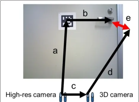
We evaluated these improvements with door lever shown in right image of Figure 10 as shown in Figure 12. In
Figure 11Improved LINE-MOD.
Figure 12, transformation a is estimated using AR marker recognition, b is measured using a scale, c is calculated as external parameters from camera calibration result, and d is estimated using LINE-MOD. Transformation e is defined as an error and we define the true positive as estimated error is less than 30 [mm] in translation and 3° in rotation. Table 3 shows the result. We used 353 frame video with various camera poses. Using original LINE-MOD, the number of true positive is 57 frames, and the number of false positive is 197 frames. Using improved LINE-MOD, the number of true positive is 60 frames, and the number of false positive is 91 frames. The proposed method can reduce false positive from 56% to 25% with no reduction of true positive.
Figure 12Image of evaluation of LINE-MOD.a: High-res camera to AR marker (estimated by marker detection and accurated enough),a: High-res camera to AR marker (estimated by marker detection and accurated enough),b: AR marker to handle (ground truth),c: High-res camera to 3D camera,d: 3D camera to handle (estimated by proposed method). Then error e is calcurated by comparisonabwithcd.
Robot teleoperation and motion teaching using 3D robot model
To achieve teleoperation and motion teaching by intuitive action generation, we develop the teleoperation system to 3D robot model using interactive marker [11]. Interactive marker is a framework adding interactive operation func-tions from users through mouse input to 3D models on rviz, 3D viewer of ROS. Using this framework, users can teach motions directly to the robot through operating 3D robot model.
In this paper, we define following 3 levels of robot action;
1) Robot centric action: operating robot’s own motion directly. Interactive markers are fixed on the robot body.
2) Environment centric action: operating built-in structures in environment. Interactive markers are fixed on the environment.
3) Object centric action: operating objects. Interactive markers are fixed on detected objects using LINE-MOD.
These 3 actions are used from our interface simultane-ously without changing modal, and robot task is realized as combination of these actions each other.
Motion teaching is also realized to record these action combination sequence and the robot can play back same task.
Table 3 Results of door lever recognition
Positive True positive False positive
Original LINE-MOD 254/353 (72%) 57/353 (16%) 197/353 (56%)
Figure 13Interactive markers for operation of HSR.Each row shows;Top: Initial state of interactive markers,Middle: Marker is operated by user interation,Bottom: Robot model is moved via operation of marker, respectively.
Robot centric action
In robot centric action, interactive markers for robot oper-ation is shown with the robot model in the 3D viewer. User can operate not only joint level action, such as base moving or head direction, but also arm reaching action with setting target hand pose using a motion planner and inverse kinematics solver.
Figure 13 shows the basic interactive operation sys-tem for HSR. In robot centric action, the robot can act following basic functions;
• Base move (Figure 13(a)) • Neck pan/tilt (Figure 13(b)) • Head up/down (Figure 13(b))
• Hand reaching to target pose (Figure 13(c)) • Gripper control
and system can also teach and play back motion combin-ing these basic functions.
To control these markers, user drags arrow or circu-lar handles arround each joints by mouse, arrow handle can set moving distance, and circular handle can instruct rotation angle such as joint angle. In case of hand reach-ing marker, user can set target hand pose usreach-ing 6 DoF arrow and circular handle directly, after setting target user click right button and select “go to target” from menu, then inverse kinematics is solved and motion is executed.
Figure 15Experimentation of pick and place.
Environment centric action
In environment centric action, to realize the operation of movable structures, interactive markers are put on environment to describe the structure of objects using parent-child relationship of interactive markers.
To put interactive markers on the environment, we construct 6 DoF interactive marker which is not associ-ated any parts but put onto the world coordinate. User can operate this marker freely and can copy anytime by right click and select “copy” from menu list. Parent-child
marker and select child marker one by one.
Focusing the door opening task as shown in Figure 14, motion of the hand pose in the door opening, it requires motions that revolving the door lever down, rotating around the pivot of the lever, and pulling the door rotat-ing around the pivot of the door. Then considerrotat-ing to put interactive markers on the door and the door lever, the door lever is fixed on the door, and the door is fixed the room. When the door is moved, the door lever is moved together with the door, however, revolving of the door lever does not effect to the door. In this case, the door lever is defined as child objects of the door. The door opening task can be described using parent-child relationship of the door pivot, the door lever pivot, and target hand poses as grasp position on the door lever.
Object centric action
In object centric action, interactive markers are put on the recognition result of known objects and achieve oper-ation teaching to object describing how to operate the object. Focusing the door structure in Figure 14 again, when recognizing the door lever as known object, rota-tional axis of the door are decided from estimated pose of the door lever, it can also adopt half-opened door or error of localization.
Results and discussion
Task operation using 3D viewer based teleoperation interface
We evaluate the proposed system with 2 teleopera-tion task experimentateleopera-tion, pick-and-place task and door opening task. In the experiments one operator achieved task.
Firstly, we achieved pick-and-place task to carry known objects from the table to the shelf. Figure 15 shows images of experimentation. In this case robot detects object on the table (1) and picks the object up which selected by the operator (2). Then the robot carries the object to the another place (3) and put it on the specified spot (4). We taught grasp pattern and target position to 3 objects which can be detected using LINE-MOD with following sequence.
1) Moving to the spot near the table (Environment centric).
2) Picking the object up (Object centric).
3) Moving to the spot near the shelf (Environment centric).
4) Putting the object on the shelf (Environment centric).
In this case, we taught a grasp pattern of objects as object centric, and spots associated the table and the shelf as environment centric. When the position of the table or the shelf is changed, the system can adopt by resetting spot’s position again by humans.
Door opening task
Secondly, we achieved door opening task. To open the door by the robot, human have to teach door axis and rotational direction, door lever axis and rotational direc-tion, the position of these parts, manipulation sequence and amount, respectively. In this experiment, door lever is defined as known object and can be detected using LINE-MOD, human teaches all remaining information.
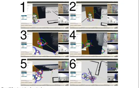
Figure 16 shows images of door opening operation. In this operation, firstly the robot stands on the front of the
door lever (1), then operator defines pivot of the door and position of the door lever putting interactive marker (2), and the door pivot and the door lever is connected by operator (3). Next the robot grasps the door lever (4), and pulls down the lever (5). Finally the robot pull the door with circular orbit, using the pivot as rotation center (6). Sequence of door opening operation is defined as;
1) Moving to the spot near the door. 2) Moving head to the door lever. 3) Grasping the door lever. 4) Revolving down the door lever.
5) Pulling the door lever rotating around pivot of the door.
6) Revolving up the door lever. 7) Holding the door lever off. 8) Leaving the door.
To achieve this sequence, we compared following 3 methods;
A) Teleoperating by human with putting interactive markers.
B) Teleoperating by human using already put interactive markers.
C) Playing back human’s teleoperation using already put interactive markers and manipulation amount.
Figure 17 shows images of the experiment. Method A) took over 600 [s], B) took 158 [s], and C) took 54 [s]. Door opening task achievements 10 times faster using taught operation sequence from human than simple teleopera-tion. Half-opened door also can be opened repeating same motion sequence using an object centric method with known object recognition using LINE-MOD as shown in Figure 18.
Note that in this experiment the door has not spring, so it does not close by itself, because the robot can-not open the door completely for its range of motion. However, this is the problem about motion planning and hardware specification, proposed method can be used in situation to open the door which has door closer.
Conclusion
In this paper, we developed 3D-viewer-based teleopera-tion user interface that is easy to use and understand for Human Support Robot HSR, and we also shew its usage example according to object pick-and-place task and door opening task. These 2 tasks can not be achieved using only dialog-based HMI because these require to move unresistered spot and to instruct phisical amount of oper-ation, proposed method can realized to achieve these diffi-cult tasks. Especially the proposed system that constructs a 3D map in unknown environments and has intuitive
teaching playback function using the virtual robot model can reduce time to achieve task drastically. When robots can construct object models in operation, the proposed task achievement method is completed in robot’s motion, it also can increase usability in real environment. In future work, we will apply operation test by the user to verify the usability of the proposed system and to derive more problems about teleoperation in the real environment.
Competing interests
This research was executed in collaborative research program of The Univ. of Tokyo and Toyota Motor Corp., and UTokyo was funded from Toyota. In this paper, atuhros include both members of UTokyo and Toyta, and there are no other organization having finantial relationship.
Authors’ contributions
HY took the lead in experimentation, implemented 3D reconstruction method, and write this paper as corresponding author. KS implemented teleoperation system and integrated all system. MK implemented and evaluated object recognition method. KS, YT and MT supervised research and support experimentation. TY and MI supervised research and presentation. All authors read and approved the final manuscript.
Author details
1Department of Information Science and Technology, The University of Tokyo, 7-3-1 Hongo Bunkyo-ku, Tokyo, Japan.2Advanced Technology Engineering Dept., Partner Robot Div., Toyota Motor Corporation, 543 Kirigahora Nishi-Hirose-cho Toyota, Aichi, Japan.
Received: 14 January 2014 Accepted: 4 July 2014
References
1. Hashimoto K, Saito F, Yamamoto T, Ikeda K (2013) A field study of the human support robot in the home environment. In: 2013 IEEE Workshop on Advanced Robotics and Its Social Impacts. IEEE Robotics and Automation Society, Tokyo, Japan, pp 143–150
2. Chitta S, Cohen B, Likhachev M (2010) Planning for autonomous door opening with a mobile manipulator. In: Robotics and Automation (ICRA), 2010 IEEE International Conference On. IEEE, Anchorage, Alaska, pp 1799–1806
3. Sturm J, Stachniss C, Burgard W (2011) A probabilistic framework for learning kinematic models of articulated objects. J Artif Intell Res (JAIR) 41:477–626
4. Azuma H, Kakiuchi Y, Saito M, Okada K, Inaba M (2011) View-base multi-touch gesture interface for furniture manipulation robots. In: IEEE Workshop on Advanced Robotics and Its Social Impacts. IEEE Robotics and Automation Society, California, USA
5. Yamazaki K, Tsubouchi T, Tomono M (2008) Furniture model creation through direct teaching to a mobile robot. J Robot Mechatronics 20(2):213–220
6. Engelhard N, Endres F, Hess J, Sturm J, Burgard W (2011) Real-time 3d visual slam with a hand-held rgb-d camera. In: Proc. of the RGB-D Workshop on 3D Perception in Robotics at the European Robotics Forum. Robotdalen, Vasteras, Sweden
7. Newcombe RA, Izadi S, Hilliges O, Molyneaux D, Kim D, Davison A. J, Kohli P, Shotton J, Hodges S, Fitzgibbon A (2011) Kinectfusion: Real-time dense surface mapping and tracking. In: IEEE ISMAR. IEEE, Basel, Switzerland
8. Furukawa Y, Curless B, Seitz SM, Szeliski R (2009) Reconstructing building interiors from images. In: Computer Vision, 2009 IEEE 12th International Conference On. IEEE, Kyoto, Japan, pp 80–87
Submit your manuscript to a
journal and benefi t from:
7 Convenient online submission
7 Rigorous peer review
7 Immediate publication on acceptance
7 Open access: articles freely available online
7 High visibility within the fi eld
7 Retaining the copyright to your article