RESEARCH ARTICLE
Real-time high-resolution video stabilization
using high-frame-rate jitter sensing
Sushil Raut
1, Kohei Shimasaki
1, Sanjay Singh
2, Takeshi Takaki
3and Idaku Ishii
3*Abstract
In this study, the novel approach of real-time video stabilization system using a high-frame-rate (HFR) jitter sensing device is demonstrated to realize the computationally efficient technique of digital video stabilization for high-res-olution image sequences. This system consists of a high-speed camera to extract and track feature points in gray-level 512×496 image sequences at 1000 fps and a high-resolution CMOS camera to capture 2048×2048 image
sequences considering their hybridization to achieve real-time stabilization. The high-speed camera functions as a real-time HFR jitter sensing device to measure an apparent jitter movement of the system by considering two ways of computational acceleration; (1) feature point extraction with a parallel processing circuit module of the Harris corner detection and (2) corresponding hundreds of feature points at the current frame to those in the neighbor ranges at the previous frame on the assumption of small frame-to-frame displacement in high-speed vision. The proposed hybrid-camera system can digitally stabilize the 2048×2048 images captured with the high-resolution CMOS camera by compensating the sensed jitter-displacement in real time for displaying to human eyes on a computer display. The experiments were conducted to demonstrate the effectiveness of hybrid-camera-based digital video stabiliza-tion such as (a) verificastabiliza-tion when the hybrid-camera system in the pan direcstabiliza-tion in front of a checkered pattern, (b) stabilization in video shooting a photographic pattern when the system moved with a mixed-displacement motion of jitter and constant low-velocity in the pan direction, and (c) stabilization in video shooting a real-world outdoor scene when an operator holding hand-held hybrid-camera module while walking on the stairs.
Keywords: Digital image stabilization, Feature point tracking, Motion estimation, High-speed real-time image stabilization
© The Author(s) 2019. This article is distributed under the terms of the Creative Commons Attribution 4.0 International License (http://creat iveco mmons .org/licen ses/by/4.0/), which permits unrestricted use, distribution, and reproduction in any medium, provided you give appropriate credit to the original author(s) and the source, provide a link to the Creative Commons license, and indicate if changes were made.
Introduction
Image stabilization [1–5] is a well-known process used to reduce undesired motion in image sequences which occur due to shaking or jiggling of a camera or rapidly moving objects while rolling the shutter. These motion anomalies are jitters, caused by various external sources responsible for the shaking of the camera, which leads to unpleasant visual effects in video sequences. Sources such as unsteady handling of the camera by an operator, rapidly moving sports camera, or camera-mounted vehi-cles or robots when maneuvering on uneven surfaces are responsible for jittery motion anomalies. The stabilization
techniques can be categorized as (1) optical image stabi-lization (OIS) and (2) digital image stabistabi-lization (DIS). The OIS systems have been designed to reduce appar-ent motion in image sequences by controlling the optical path sensed by sensors such as gyroscopes or accelerom-eters. The lens-shift OIS systems shift their optical path using optomechatronic devices such as a lens-barrel-shift mechanism [6, 7], a fluidic prism [8], a magnetic 3-DOF platform [9], a deformable mirror [10], sensor-shift OIS systems to shift their image sensors using voice coil actu-ators [11–15], and hand-held OIS systems with multi-DOF gimbal control systems [16–19] have been reported by researchers. Recent consumer digital cameras have the OIS stabilization functions to remove inevitable and undesired fluctuating motion while capturing video. These OIS systems can stabilize input images by reduc-ing the motion blur induced by camera shake. However,
Open Access
*Correspondence: [email protected] 3 Department of System Cybernetics, Hiroshima University, Higashi-Hiroshima, Japan
conventional systems have difficulty in perfectly reduc-ing large and quick apparent motion by controllreduc-ing the optical path with sensors that cannot detect any appar-ent motion in images, due to the physical limitations in the lens-shift or sensor-shift mechanisms. For frame-by-frame image stabilization in video sequence, the DIS systems can produce a compensated video sequence. The residual fluctuated motion in images can be reduced using various image processing techniques to estimate the local motion vectors, such as block matching [20– 23], bit-plane matching [24, 25], Kalman-filter-based prediction [26–30], DFT filtering [31], particle filter [32], scale-invariant feature [33, 34], feature point matching [35–39], and optical flow estimation [40–45]. These sys-tems do not require any additional mechanism or optical device for video stabilization, and they have been used as low-cost video stabilizers in various applications such as airborne shooting [46–52], off-road vehicles [53], and teleoperated applications [54–57], including commer-cial applications [58–62]. Researchers have been report-ing various approaches to achieve real-time DIS systems [63–69] for stabilizing a video sequence with simultane-ous video processing at conventional frame rate, whereas most of them have limited ability to reduce large and quick apparent motion observed in images due to heavy computation in the frame corresponding process.
With rapid advancements in computer vision technolo-gies, various real-time high-frame-rate (HFR) vision sys-tems operating at 1000 fps or more have been developed [70–73], and their effectiveness has been demonstrated in tracking applications such as robot manipulations [74–77], multi-copter tracking [78, 79], optical flow [80], camshift tracking [81], multi-object tracking [82], feature point tracking [83], and face tracking [84]. These systems were computationally accelerated by parallel-implemen-tation on field-programmable gate arrays (FPGAs) and graphics processing units (GPUs) to obtain real-time HFR video processing. If a real-time HFR vision system could simultaneously estimate the apparent motion in images at a high framerate in a manner similar to that of conventional sensors, it could made to function as an HFR jitter sensor for DIS-based video stabilization even when the camera or the targeted scene moves quickly.
In this paper, we introduced a concept of real-time digital video stabilization with HFR video processing, in which an HFR vision system can simultaneously esti-mate apparent translational motion in image sequences as an HFR jitter sensor and is hybridized to assist for compensating high-resolution image sequences. We developed a hybrid-camera system for real-time high-resolution video stabilization that can simultaneously stabilize 2048×2048 images captured at 80 fps by exe-cuting frame-by-frame feature point tracking in real time
at 1000 fps on a 512×512 HFR vision system. Its perfor-mance was demonstrated by the experimental results for several moving scenes.
Video stabilization using HFR jitter sensing Concept
Most of the feature-based DIS methods are realized by executing (1) feature extraction, (2) feature point match-ing, (3) frame-by-frame transform estimation, and (4) composition of jitter-compensated image sequences. Corresponding to steps (1)–(3), feature-based motion estimation at the frame rate of conventional cameras is not always stable and there are chances of inaccurate reduction of large apparent motions when a camera moves rapidly. This leads to heavy computation caused by large image displacements between frames. Narrow-ing the search range by assumNarrow-ing temporal redundancy in HFR image sequences can accelerate the process of frame-by-frame motion estimation, whereas video stabi-lization using HFR image sequences has a shortcoming in image-space resolution and brightness; the former is restricted by the specification of an image sensor as well as the processing power for motion estimation, and the latter depends on its short exposure time, which is less than the frame cycle time of the HFR camera. Thus, we introduce the concept of hybrid-camera-based digital video stabilization that can solve this trade-off between the tracking accuracy in real-time motion estimation and the space resolution in composing a compensated video sequence. The hybrid-camera-based system consists of a high-speed vision system that can extract and track the feature points in consecutive images in real time at thousands of frames for fast apparent motion estimation as an HFR jitter sensor in steps (1)–(3), and a reso-lution camera system for composing compensated high-resolution sequences at dozens of frames per seconds convenient for human eyes in step (4). It is assumed that these camera systems have overlapped views of scenes or objects in the view field. Our approach has the following advantages over conventional methods:
(a) Motion estimation accelerated by assuming HFR image sequences
frames. Assuming that one or a small number of feature points at the previous frame are detected in the narrowed neighborhood of each feature point at the current frame, this narrowed neighborhood search can reduce the computational complexity in feature point matching in the order of O(M). (b) Stabilization of high-resolution image sequences
Generally, real-time video stabilization aims to reduce fluctuated motions in image sequences to generate compensated videos convenient for human eyes on a computer display. Most displays are designed to operate at tens of frames per sec-ond, which is enough for human eyes to perceive it as a smooth movie. If a high-resolution camera of N′
x×Ny pixels can capture a tens of frames per ′ second video sequence for a view similar to that in the HFR image sequence when mounted on the same platform, both cameras can experience the same desired and undesired motion at the same time. Hence a jitter-compensated N′
x×Ny image ′ sequence can be composed in real time without heavy computational complexity for HFR image synthesis; the high-speed vision system works as an HFR jitter sensor to determine jitter-compensation parameters.
Algorithm for jitter sensing and stabilization
Our algorithm for hybrid-camera-based digital video stabilization consists of the following processes. In the steps of (1) feature point extraction and (2) feature point matching, we used the same algorithms as those used in real-time image mosaicking using an HFR video [83], considering the implementation of parallelized gradient-based feature extraction on an FPGA-gradient-based high-speed vision platform.
Feature point detection
The Harris corner feature [85],
(x,tk)= det C(x,tk)−κ(Tr C(x,tk))2 at time tk , is
computed using the following gradient matrix:
where Na(x) is the a×a adjacent area of pixel x=(x,y) .
tk =kt indicates when the input image I(x,t) at frame k is captured by a high-speed vision system operating at a frame cycle time of t . I′
x(x,t) and Iy′(x,t) indicate the positive values of x and y differentials of the input image I(x,t) at pixel x at time t, Ix(x,t) and Iy(x,t) , respectively.
κ is a tunable sensitive parameter, and values in the range 0.04–0.15 have been reported as feasible.
(1) C(x,tk)=
x∈Na(x)
I′2
x (x,tk) Ix′(x,tk)Iy′(x,tk) I′
x(x,tk)Iy′(x,tk) Iy′2(x,tk)
,
The number of feature points in the p×p adjacent area of x is computed as the density of feature points by
thresholding (x,tk) with a threshold T as follows:
where R(x,t) is a map of feature points.
Closely crowded feature points are excluded by count-ing the number of feature points in the neighbour-hood. The reduced set of feature points is calculated as R′(t
k)= {x|P(x,tk)≤P0} by thresholding P(tk) with
a threshold P0 . It is assumed that the number of feature
points is less than M.
Feature point matching
To enable correspondence between feature points at the current time tk and those at the previous time tk−1=(k−1)�t , template matching is conducted for all the selected feature points in an image.
To enable the correspondence of the i-th feature point at time tk−1 belonging to R′(tk−1) , xi(tk−1)(1≤i≤M) ,
to the i′-th feature point at time tk belonging to R′(t k) ,
xi′(tk)(1≤i′≤M) , the sum of squared differences is cal-culated in the window Wm of m×m pixels as follows:
To decrease the number of mismatched points,
ˆ
x(xi(tk−1);tk) and xˆ(xi′(t);tk−1) , which indicate the feature point at time tk corresponding to the i-th
fea-ture point xi(tk−1) at time tk−1 , and the feature point at
time tk−1 corresponding to the i′-th feature point xi′(tk) at time tk , respectively, are bidirectionally searched so that E(i′,i;t
k,tk−1) is minimal in their adjacent areas as
follows:
where i′(i) and i(i′) are the index numbers of the feature point at time tk corresponding to xi(tk−1) , and that at time tk−1 corresponding to xi′(tk) , respectively. Accord-ing to mutual selection of the correspondAccord-ing feature points, the pair of feature points between time tk and tk−1
are selected as follows:
(2) P(x,tk)=
x′∈Np(x)
R(x′,t k),
R(x,tk)=
1 ((x,tk) >T)
0 (otherwise) ,
(3)
E(i′,i
;t,tk−1)=
ξ=(ξ,η)∈Wm
�I(xi′(t)+ξ,t)
−I(xi(tk−1)+ξ,tk−1)
2 . (4) ˆ
x(xi(tk−1);tk)=xi′(i)(tk)= arg min xi′(tk)∈Nb(xi(tk−1))
E(i′,i
;tk,tk−1),
(5) ˆ
x(xi′(tk);tk−1)=xi(i′)(tk−1)
= arg min
xi(tk−1)∈Nb(xi′(tk)) E(i′,i
where fi(tk) indicates whether there are feature points
at time tk or not, corresponding to the i-th feature point
xi(tk
−1) at time tk−1.
On the assumption that the frame-by-frame image-dis-placement between time tk and tk−1 is small, the feature
point xi(tk) at time tk is matched with a feature point at time tk−1 in the b×b adjacent area of xi(tk) ; the compu-tational load of feature point matching is reduced in the order of O(M) by setting a narrowed search range. For all the feature points belonging to R′(t
k−1) and R′(tk) , the
processes described in Eqs. (4)–(7) are conducted, and M′(t
k)(≤M) pairs of feature points are selected for jitter sensing, where M′(t
k)=Mi=1fi(tk).
Jitter sensing
Assuming that the image-displacement between time tk
and tk−1 is translational motion, the velocity v(tk) at time
tk is estimated by averaging the positions of selected pairs of feature points as follows:
Jitter displacement d(tk) is computed at time tk by
accumulating the estimated velocity v(tk) as follows:
where the displacement at time t=t0=0 is initially set to d(t0)=d(0)=0 . The high-frequency component of
jitter displacement dcut(tk) , which is the camera jitter movement intended for removal is extracted using the following high-pass IIR filter,
where the order of the IIR filter is D; it is designed to exclude the low-frequency component of velocity lower than a cut-off frequency fcut.
Composition of jitter‑compensated image sequences
When the high-resolution input image I′(x′,t′
k′) at frame k′ is captured at time t′
k′ =k′t′ by a high-resolution camera operating at a frame cycle time of t′ , which is much larger than that of the high-speed vision sys-tem, t , the stabilized high-resolution image S(x′,t′
k′)
(6) ˜
xi(tk)=
ˆ
x(xi(tk−1);tk) (i=i(i′(i))) ∅ (otherwise) ,
(7) fi(tk)=
1 (i=i(i′(i))) 0 (otherwise) ,
(8) v(tk)=
1 �t ·
1
M′(t k)
M
i=1
fi(tk)(x˜i(tk)−xi(tk−1)),
(9)
d(tk)=d(tk−1)+v(vk−1)·�t,
(10) dcut(tk)= IIR(dk,dk−1,. . .,dk−D;fcut),
is composed by displacing I′(x′,t′
k′) with the high-fre-quency component of jitter displacement dcut(ˆt′
k′) as follows:
where x′
=lx indicates the image coordinate system of the high-resolution camera; its resolution is l times that of the high-speed vision system. ˆt′
k′ is the time when the
high-speed vision system captures its image at the near-est frame after time t′
k′ when the high-resolution camera captures its image as follows:
where ⌈a⌉ indicates the minimum integer, which is larger
than a.
In this way, video stabilization of high-resolution image sequences can be achieved in real time by image compo-sition using input sequences based on a high-frequency-displacement component sensed by executing the high-speed vision system as an HFR jitter sensor.
Real‑time video stabilization system System configuration
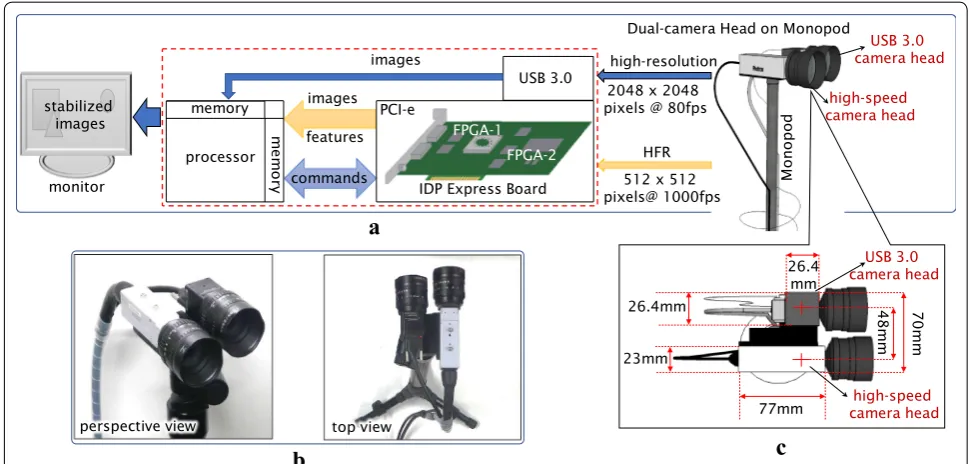
To realize real-time high-resolution video stabilization, we implemented our algorithm on a hybrid-camera sys-tem. It consists of an FPGA-based high-speed vision device, the IDP-Express [72], a high-resolution USB 3.0 camera (XIMEA, MQ042-CM), and a personal computer (PC). Figure 1 shows (a) the system configuration, (b) the overview of its dual-camera head when mounted on a monopod, and (c) its top-view geometric configuration. IDP Express consists of a camera head that can capture gray-level 8-bit 512×512 images at 2000 fps, and a dedi-cated FPGA board for hardware-implementation of the user-specific algorithms. The image sensor of the camera head is a 512×512 CMOS sensor of 5.12×5.12 mm-size at 10×10µm-pitch.
On the dedicated FPGA board, the 8-bit gray-level
512×512 images could be processed in real time with circuit logic on the FPGA (Xilinx XC3S5000); the captured images and processed results could be transferred to memory allocated in the PC. The high-resolution camera MQ042-CM can capture gray-level 8-bit 2048×2048 images, and these images can be transferred at 90 fps via a USB 3.0 interface to a PC; the sensor-size and pixel-pitch are 11.26×11.26 mm and 5.5×5.5µm , respectively. We used a Windows 7(64 bit)-OS installed PC (Hewlett Packard, Z440 work-station) with the following specifications: Intel Xeon E5-1603v4 at 2.8 GHz, 10 MB cache, 4 cores, 16 GB DDR4 RAM, two 16-lane PCI-e 3.0 buses, and four (11)
S(x′,t′
k′)=I′(x′−l·dcut(tˆk′′),tk′′),
(12) ˆ
t′
USB 3.0 ports. As illustrated in Fig. 1, the camera head of the IDP Express (camera 1) and the high-resolution camera MQ042-CM (camera 2) were installed in such a way that the optical axis of their lenses were paral-lel; the distance between the two axes was 48 mm. The hybrid-camera system was attached on a monopod of length variable from 55 to 161 cm for hand-held
operation. Identical CCTV lenses of f = 25 mm were
attached to both cameras 1 and 2. As shown in Fig. 2, when the hybrid-camera module was placed 5 m away from the patterned scene (a) the high-resolution image captured by camera 2 could observe 2.20×2.20 m-area and (b) camera 1 could observe 1.01×1.01 m-area. If we observe scenes when the measurement area of
Mo
no
po
d
Dual-camera Head on Monopod
a
512 x 512 pixels@ 1000fps
HFR high-resolution
2048 x 2048 pixels @ 80fps
IDP Express Board monitor
USB 3.0
PCI-e
commands processor
memory
me
mo
ry
images
features images
stabilized images
48
mm
70m
m
77mm 26.4
mm 26.4mm
23mm
c
b
perspective view top view
high-speed camera head
USB 3.0 camera head
high-speed camera head
USB 3.0 camera head
FPGA-1 FPGA-2
Fig. 1 Hybrid-camera system for real-time video stabilization a configuration, b dual-camera head, c top-view geometric configuration
1010 mm
1010
mm
2200 mm
2200
mm
a b
Fig. 2 Input images of patterned objects captured at a distance of 5 m a high-resolution camera (camera 2: 2048×2048 ), b high-speed camera
camera 1 is completely involved in that of camera 2, the high-speed vision system works as an HFR jitter sensor for stabilizing the 2048×2048 images of camera 2, as discussed earlier.
Specifications
The feature point extraction process in step (1) was accel-erated by hardware-based implementation of a feature extraction module [83] on the FPGA. The dedicated FPGA extracts feature points in a 512×512 image, and the xy coordinates of the feature points appended at the bottom 16 rows of an ROI input image of 512×496 pix-els. The implemented Harris corner feature extraction module is illustrated in Fig. 3. In step (1), the area size and the tunable sensitive parameter in computing the Harris corner features were set to a= 3 and κ= 0.0625,
respectively. The area size for extracting the number of feature points was set to p= 8. According to the
experi-mental scene, parameters T and P0 were determined
so that the number of feature points must be less than
M= 300.
Steps (2)–(4) were software-implemented on the PC. In step (2), we assumed that the number of selected feature points were less than M= 300, and that 5×5(m=5) template matching with bidirectional search in the 31×31(b=31) adjacent area was executed. In step (3),
the high-frequency component of the frame-by-frame image displacement is extracted as its jitter displacement to be compensated by executing a 5th-order Butterworth high-pass filter ( D=5).
The high-speed vision system captured and processed 512×496 ( Nx =512 , Ny=496 ) at 1000 fps, correspond-ing to t= 1 ms, whereas the high-resolution camera set
for capturing 2048×2048 ( Nx′ =Ny′=2048 ) at 80 fps in step (4), corresponding to t′
= 12.5 ms.
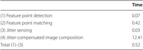
Table 1 summarizes the execution times of steps (1)–(4) when our algorithm was implemented on the
hybrid-camera system with the parameters stated above. The execution time of step (1) includes the image acquisi-tion time for a 512×512 image on the FPGA board of the high-speed vision system. The total execution time of steps (1)–(3) was less than the frame cycle time of the high-speed vision system, t= 1 ms. Due to the higher
synthesizing cost for 2048×2048 image sequences, the execution time of step (4) was much larger than that of the other steps, but it was less than the frame cycle time of the high-resolution camera t′= 12.5 ms. Here steps
(2)–(4) were software-implemented as multithreaded processes to achieve real-time jitter sensing at 1000 fps in parallel with real-time composition of jitter-compensated high-resolution images at 80 fps so as to simultaneously display it on a computer display.
We compared our algorithm with conventional meth-ods for feature-based video stabilization using SURF [5], SIFT [86], FAST [87], and Harris corner [88], which are distributed in the OpenCV standard library [89]. Table 2 shows the execution times for step (1) and steps (2)–(4) when conventional methods for 512×496 and 2048×2048 images on the same PC as that used in our hybrid-camera system. These methods involved the pro-cesses for steps (2)–(4) such as descriptor matching, aff-ine transformation for displacement estimation, Kalman
2
2
TrC
36bit x 4 detC
35bit x 4
feature
35bit x 4
16 parallel 20bit
x3x4 gray
image
I( , )
8bit x 4 input
image
F( , )
8bit x 4
4 parallel 4 parallel 4 parallel 4 parallel
feature point
E( , )
8bit x 4
Harris Corner Detection Submodule
feature point
map
B( , )
1bit x 4
4 parallel ′ ( , ) ba ye r-to -Gra y Co nv er te r mu ltip licati on & su mma ti on mu ltip licatio n & su bt ract io n HF R Camera fe at ur e po int co un te r th resh ol di ng su bm od ul e Pe rs on al Comp ut er tr ace & de te rm in an t
Fig. 3 Hardware circuit module for Harris corner feature extraction
Table 1 Execution times on our hybrid camera system (unit: ms)
Time
(1) Feature point detection 0.07
(2) Feature point matching 0.42
(3) Jitter sensing 0.03
(4) Jitter-compensated image composition 12.41
filtering for jitter removal, and stabilized image com-position. In the evaluation, we assume that the number of feature points to be selected in step (1) are less than
M=300 in both the cases of 512×496 and 2048×2048 images. As shown in Table 2, the computational cost for synthesizing 2048×2048 images is expressively higher than that for 512×496 images.
Our algorithm can accelerate the execution time of steps (2)–(4) for video stabilization of 2048×2048 images to 12.41 ms by hybridizing the hardware-implemented feature extraction of 512×496 images in step (1). We confirmed that our method could sense the jitter of several HFR videos, in which frame-by-frame image displacements are small, at the same accuracy level as those of conventional methods. The latter involve a matching process with predictions such as the Kalman filter to compensate certain image displacements between frames in a standard video at dozens of frames per second. Similarly, with the
feature point extraction process, such a matching pro-cess with prediction is time consuming to the extent that conventional methods cannot be executed for the real-time video stabilization of 2048×2048 images at dozens of frames per second. Thus, our hybridized algorithm for video stabilization of high-resolution images has computational advantages over conven-tional feature-based stabilization methods.
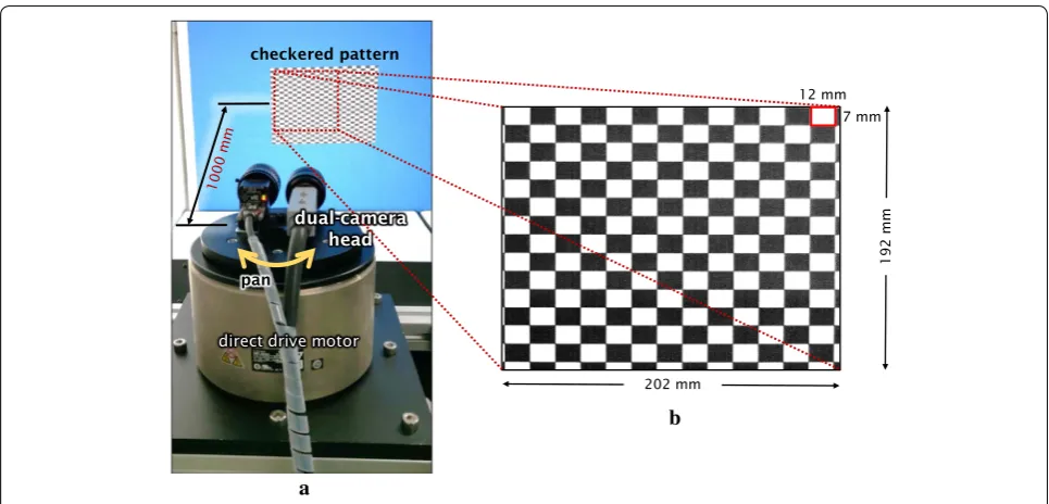
Experiments Checkered pattern
Firstly, we evaluated the performance of our system in video stabilization by observing a static checkered pat-tern when a hybrid-camera system vibrated mechanically in the pan direction, as illustrated in Fig. 4. The hybrid-camera system was mounted on a direct drive AC servo motor (Yaskawa, SGM7F-25C7A11) so as to mechani-cally change its pan angle, and a 12×7 mm-pitch Table 2 Comparison in execution time (unit: ms)
Methods 512×496 2048×2048
Step (1) Steps (2)–(4) Step (1) Steps (2)–(4)
SURF features [87] 84.03 20.47 742.64 107.59
SIFT features [86] 147.85 12.44 2194.79 131.19
FAST features [5] 0.56 11.44 3.19 88.91
Harris features (SW) [88] 19.56 18.41 219.33 174.82
Harris features (HW) [our method] 0.07 0.45 – 12.41
202 mm
7 mm 12 mm
b
192 mm
checkered pattern
a
pan
direct drive motor
dual-camera head
checkered pattern was installed 1000 mm in front of the camera system. The measurement area observed in the 512×496 image of camera 1 corresponded to 202×192 mm on the checkered pattern.
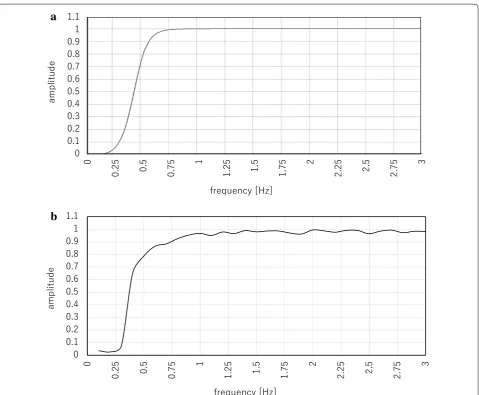
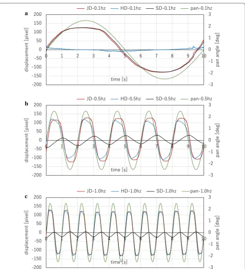
In the pan direction, the hybrid-camera system vibrated on the 2.5-degree-amplitude sinusoid trajectories at various frequencies ranging from 0.1 Hz to 3 Hz with increments of 0.1 Hz. This camera ego-motion exhib-ited 120-pixel displacement in the horizontal direc-tion in the camera 1 image. The threshold parameters in the feature extraction step were set to T = 5×10⁷ and P0= 15, and the cut-off frequency in the jitter sensing step was set to fcut = 0.5 Hz. Figure 5a the response of a
5th-order Butterworth high-pass filter, of which the cut-off frequency is 0.5 Hz, and (b) the relationship between the vibration frequencies and the damping ratios in the jitter cancellation on our system. The damping ratio was computed as the ratio of the standard deviation of the fil-tered high-frequency component to that of the jitter dis-placement in the horizontal direction for 10 s. Figure 6 shows the pan angles of the hybrid-camera system, the jitter displacements (JDs), their filtered high-frequency component displacements (HDs), and the stabilized dis-placements (SDs) in the horizontal direction in the cam-era 1 image for 10 s when the hybrid-camcam-era system was vibrated at 0.1, 0.5, and 1.0 Hz. The SDs were computed
a
b
a
b
c
Fig. 6 Pan angles, jitter displacements (JDs), filtered high-frequency components (HDs), and stabilized displacements (SDs) when a hybrid-camera
192m
m
m
m
0
4
4
440mm 202mm
camera 2 (2048x2048) camera 1 (512x496)
1200mm
900m
m
dual-camera head
pan-tilt motor head
1000 mm
pan
a
b
Fig. 7 Experimental setup for observation of a cityscape photographic pattern a overview, b scenes observed by camera 1 and camera 2
by canceling the HDs from the JDs. According to the cut-off frequency at 0.5 Hz, it can be observed that the SD was almost matched with the JD when the vibration was done at 0.1 Hz, whereas the SD tended toward zero with 1.0 Hz vibration. This tendency can be confirmed in Fig. 5 where it can be observed that our system detected and canceled a specified high-frequency camera jitter displacement and that the damping ratio was largely varied from 1 to 0 around the cut-off frequency fcut = 0.5 Hz.
Photographic pattern
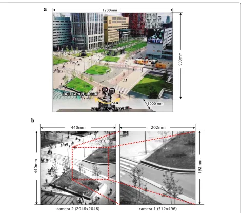
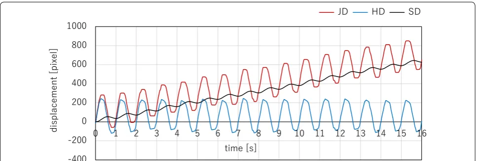
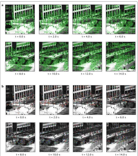
Next, we evaluated the video stabilization performance by observing a printed photographic pattern when the hybrid-camera system moved with drifting at a cer-tain frequency in the pan direction. Figure 7a shows the experimental setup, which was set up in the same way as that in the previous subsection. A printed cityscape photographic pattern of dimensions 1200×900 mm was placed 1000 mm in front of the hybrid-camera system mounted on a pan-tilt motor head. On the pattern, the 440×440 mm area observed by camera 2 involved and the 202×192 mm area observed by camera 1 are illus-trated in Fig. 7b. In the experiment, the pan angle varied with 1 Hz vibration as illustrated in Fig. 8. The param-eters in the feature extraction step and the cut-off fre-quency in the jitter sensing step were set to the same values as those in the previous subsection. Figure 9 shows the JD, the HD, and the SD in the horizontal direction in the camera 1 image for 16 s when the hybrid-camera sys-tem drifted with 1 Hz vibration in the pan direction. In Fig. 10a the extracted feature points (green ‘+’) and (b) the pairs of the matched feature points between previous and current frames (blue and red dots) were plotted in the 512×496 input images of camera 1. Figure 11a the
2048×2048 input images and (b) the stabilized images of camera 2. The images in Figs. 10 and 11 were taken for t= 0–14 s with an interval of 2 s. Figure 12 a the
2048×2048 input images and (b) their stabilized images of camera 2 from t= 0 to 0.7 s, taken at intervals of 0.1
s. In Fig. 9, the SD was obtained as the DC component by reducing the 1 Hz vibration in the camera drift, which is higher than the cut-off frequency of 0.5 Hz. The stabi-lized images of camera 2 for 0.7 s in Fig. 12b were com-pensated so as to cancel the 1 Hz vibration, whereas the apparent left-to-right motion of the cityscape scene for 14 s in the stabilized images of camera 2, which corre-sponded to the DC component in the camera drift, were not canceled, as illustrated in Fig. 11b. These experimen-tal results show that our hybrid-camera system can auto-matically stabilize 2048×2048 images of complex scenes so as to cancel high-frequency components in the camera ego-motion.
Outdoor scene
To demonstrate the performance of our proposed system in a real-world scenario, we conducted an experiment when an operator was holding a hand-held dual-camera head of our hybrid-camera system while walking on out-door stairs where undesired camera ego-motion usually induces unpleasant jitter displacements in video shoot-ing. Figure 13 shows the experimental scene when walk-ing down on outdoor stairs holdwalk-ing a dual-camera head. It was mounted on a 70 cm-long monopod. In the experi-ment, we captured an outdoor scene of walking multiple persons with background trees; they were walking on the stairs at a distance of 2 to 4 m from the operator. Induced by left-and-right hand-arm movement and up-and-down body movement while walking, the dual camera head was
t = 12.0 s
t = 0.0 s t = 2.0 s t = 4.0 s t = 6.0 s
t = 8.0 s t = 10.0 s t = 14.0 s
t = 12.0 s
t = 0.0 s t = 2.0 s t = 4.0 s t = 6.0 s
t = 8.0 s t = 10.0 s t = 14.0 s
a
b
Fig. 10 Feature points plotted on 512×496 input images of camera 1 when observing a photographic pattern a extracted feature points, b pairs
t = 12.0 s
t = 0.0 s t = 2.0 s t = 4.0 s t = 6.0 s
t = 8.0 s t = 10.0 s t = 14.0 s
t = 12.0 s
t = 0.0 s t = 2.0 s t = 4.0 s t = 6.0 s
t = 8.0 s t = 10.0 s t = 14.0 s
a
b
t = 0.6 s
t = 0.0 s t = 0.1 s t = 0.2 s t = 0.3 s
t = 0.4 s t = 0.5 s t = 0.7 s
t = 0.6 s
t = 0.0 s t = 0.1 s t = 0.2 s t = 0.3 s
t = 0.4 s t = 0.5 s t = 0.7 s
a
b
repeatedly panned in the horizontal direction and moved in the vertical direction around 1 Hz. At a distance of 3 m from the operator, an area of 1.30×1.30 m corresponded to a 2048×2048 input image of camera 2, which involved an area of 0.60×0.55 m observed in a 512×496 image of camera 1. The threshold parameters in the feature extrac-tion step were set to T = 5×10⁷ and P0= 15, and M=
300 feature points or less were selected for feature point matching. The cut-off frequency in the jitter sensing step was set to fcut = 0.5 Hz. to reduce the 1 Hz camera jitter in the experiment.
Figure 14 shows the JDs, the HDs, and the SDs in (a) the vertical direction and (b) the horizontal direction in the camera 1 image for t= 0-7 s. Figure 15 shows (a) the extracted feature points and (b) the pairs of matched feature points, which are plotted in the 512×496 input images of camera 1. Figure 16 shows (a) the 2048×2048 input images and (b) the stabilized images of camera 2. Additionally, 2048×2048 images are stabilized in real time at an interval of 12.41 ms; the fastest rate of our sta-bilization is 80.6 fps. The images in Figs. 15 and 16 for t= 0–6.16 s with an interval of 0.88 s were used to monitor whether the camera ego-motion at approximately 1 Hz was reduced in the stabilized images. According to ras-ter scanning from the upper left to the lower right in the camera 1 image, feature points in its upper region were selected for feature point matching when their number was much larger than 300. Thus, as illustrated in Fig. 15b, only 300 feature points located on the background trees in the upper region of the camera 1 image were selected for feature point matching in all the frames and those around walking persons in the center and lower regions were ignored. Video stabilization was conducted based on the static background trees, ignoring the dynami-cally changing appearances of the walking persons in the center and lower regions of the camera 1 image. In Fig. 14, the JDs in both the horizontal and vertical direc-tions time-varied at approximately 1 Hz, correspond-ing to the frequency of the camera ego-motion, which was determined by the relative geometrical relationship between the dual-camera head and the static background trees. It can be observed that the SDs were obtained as the low-frequency component by reducing the high-frequency jitter component, and that the 2048×2048 images were stabilized so as to significantly reduce the apparent motion of the background objects such as trees and a handrail of stairs in the images, as illustrated in Fig. 16b. We confirmed that the camera jitter with the operator’s quick hand motion and the 1 Hz camera jitter in the experiment were correctly measured as the back-ground objects were always observed, with naked eyes in real time, as semi-stationary objects in the stabilized images when they were displayed on a computer display. By selecting the feature points in the static background for feature point matching, our hybrid-camera system can correctly stabilize 2048×2048 images in real time without disturbance from the dynamically changing appearances around the walking persons when assisted by feature-point-based HFR-jitter sensing at 1000 fps
18 stairs (~4m)
operator
scene to be observed
dual-camera head
monopod
Fig. 13 Experimental scene when walking on stairs with a
even when a walking operator moves the hand-held dual-camera head of our system quickly. Here, the frequency of the camera jitter may increase depending on the oper-ator’s motion, however, our system is capable of stabiliz-ing frequencies much higher than 1 Hz. The operator’s motion in the frequency range from 0.5 to 10 Hz can be compensated for video stabilization on our system.
Conclusions
In this study, we developed a hybrid-camera-based video stabilization system that can stabilize high-resolution images of 2048×2048 pixels in real time by estimating the jitter displacements of the camera assisted by an HFR vision system operating at 1000 fps. Several experiments were conducted with real scenes in which the hybrid-camera system had certain jitter displacements due to its mechanical movement, and the experimental results
verified its performance for real-time video stabilization with HFR video processing. For real-time video stabiliza-tion, our method was designed only for reducing transla-tional movements in images; it cannot perfectly reduce camera jitter with large rotational movements. Accuracy in jitter sensing using our method will decrease significantly when feature points around moving targets are selected for feature point matching. Based on these results, we aim to improve our video stabilization system for more robust usage in complicated Scenes with 3-D translational and rotational movements under time-varying illumination, with object recognition and motion segmentation to seg-regate the camera motion by intelligently ignoring feature points around moving objects such as persons and cars, and to extend it to create embedded and consumer cam-era systems for mobile robots and systems for a variety of applications.
a
b
Fig. 14 Jitter displacement (JD), filtered high-frequency component (HD), and stabilized displacement (SD) in outdoor stair experiment a
t = 5.28 s
t = 0.0 s t = 0.88 s t = 1.76 s t = 2.64 s
t = 3.52 s t = 4.40 s t = 6.16 s
t = 5.28 s
t = 0.0 s t = 0.88 s t = 1.76 s t = 2.64 s
t = 3.52 s t = 4.40 s t = 6.16 s
a
b
Fig. 15 Feature points plotted on 512×496 input images of camera 1 in outdoor stair experiment a extracted features points, b pairs of matched
t = 5.28 s
t = 0.0 s t = 0.88 s t = 1.76 s t = 2.64 s
t = 3.52 s t = 4.40 s t = 6.16 s
t = 5.28 s
t = 0.0 s t = 0.88 s t = 1.76 s t = 2.64 s
t = 3.52 s t = 4.40 s t = 6.16 s
a
b
Acknowledgements Not applicable.
Authors’ contributions
SR carried out the main part of this study and drafted the manuscript. SR and KS set up the experimental system of this study. SS, TT, and II contributed con-cepts for this study and revised the manuscript. All authors read and approved the final manuscript.
Funding Not applicable.
Availability of data and materials Not applicable.
Ethics approval and consent to participate Not applicable.
Consent for publication Not applicable.
Competing interests
The authors declare that they have no competing interests.
Author details
1 Digital Monozukuri (Manufacturing) Education Research Center, Hiroshima University, Higashi-Hiroshima, Japan. 2 Cognitive Computing Group, Cyber Physical Systems Area, CSIR-Central Electronics Engineering Research Institute, Pilani, India. 3 Department of System Cybernetics, Hiroshima University, Higashi-Hiroshima, Japan.
Received: 28 July 2019 Accepted: 2 November 2019
References
1. Morimoto C, Chellappa R (1996) Fast electronic digital image stabilization. IEEE Proc ICPR 3:284–288
2. Scott W, Sergio R (2006) Introduction to image stabilization. SPIE Press, Bellingham. https ://doi.org/10.1117/3.68501 1
3. Yang J, Schonfeld D, Mohamed M (2009) Robust video stabilization based on particle filter tracking of projected camera motion. IEEE Trans Circuits Syst Video Technol 19(7):945–954
4. Amanatiadis A, Gasteratos A, Papadakis S, Kaburlasos V, Ude A (2010) Image stabilization, ARVRV. IntechOpen, New York, pp 261–274 5. Xu J, Chang HW, Yang S, Wang D (2012) Fast feature-based video
stabiliza-tion without accumulative global mostabiliza-tion estimastabiliza-tion. IEEE Trans Consum Electron 58(3):993–999
6. Kusaka H, Tsuchida Y, Shimohata T (2012) Control technology for optical image stabilization. SMPTE Motion Imag J 111:609–615
7. Cardani B (2006) Optical image stabilization for digital cameras. IEEE Control Syst 26:21–22
8. Sato K, Ishizuka S, Nikami A, Sato M (1993) Control techniques for optical image stabilizing system. IEEE Trans Consum Electron 39:461–466 9. Pournazari P, Nagamune R, Chiao MA (2014) Concept of a magnetically
actuated optical image stabilizer for mobile applications. IEEE Trans Consum Electron 60:10–17
10. Hao Q, Cheng X, Kang J, Jiang Y (2015) An image stabilization optical system using deformable freeform mirrors. Sensors 15:1736–1749 11. Chiu CW, Chao PCP, Wu DY (2007) Optimal design of magnetically
actu-ated optical image stabilizer mechanism for cameras in mobile phones via genetic algorithm. IEEE Trans Magn 43:2582–2584
12. Moon J, Jung S (2008) Implementation of an image stabilization system for a small digital camera. IEEE Trans Consum Electron 54:206–212 13. Song M, Hur Y, Park N, Park K, Park Y, Lim S, Park J (2009) Design of a
voice-coil actuator for optical image stabilization based on genetic algorithm. IEEE Trans Magn 45:4558–4561
14. Song M, Baek H, Park N, Park K, Yoon T, Park Y, Lim S (2010) Development of small sized actuator with compliant mechanism for optical image stabilization. IEEE Trans Magn 46:2369–2372
15. Li TS, Chen C, Su Y (2012) Optical image stabilizing system using fuzzy sliding-mode controller for digital cameras. IEEE Trans Consum Electron 58(2):237–245. https ://doi.org/10.1109/TCE.2012.62274 18
16. Walrath CD (1984) Adaptive bearing friction compensation based on recent knowledge of dynamic friction. Automatica 20:717–727 17. Ekstrand B (2001) Equations of motion for a two-axes gimbal system. IEEE
Trans Aerosp Electron Syst 37:1083–1091
18. Kennedy PJ, Kennedy RL (2003) Direct versus indirect line of sight (LOS) stabilization. IEEE Trans Control Syst Technol 11:3–15
19. Zhou X, Jia Y, Zhao Q, Yu R (2016) Experimental validation of a compound control scheme for a two-axis inertially stabilized platform with multi-sensors in an unmanned helicopter-based airborne power line inspec-tion system. Sensors. https ://doi.org/10.3390/s1603 0366
20. Jang SW, Pomplun M, Kim GY, Choi HI (2005) Adaptive robust estima-tion of affine parameters from block moestima-tion vectors. Image Vis Comput 23:1250–1263
21. Xu L, Lin X (2006) Digital image stabilization based on circular block matching. IEEE Trans Consum Electron 52(2):566–574. https ://doi. org/10.1109/TCE.2006.16496 81
22. Moshe Y, Hel-Or H (2009) Video block motion estimation based on gray-code kernel. IEEE Trans Image Process 18(10):2243–2254. https ://doi. org/10.1109/TIP.2009.20255 59
23. Chantara W, Mun JH, Shin DW, Ho YS (2015) Object tracking using adap-tive template matching. IEIE SPC 4:1–9
24. Ko S, Lee S, Lee K (1998) Digital image stabilizing algorithms based on bit-plane matching. IEEE Trans Consum Electron 44:617–622 25. Ko S, Lee S, Jeon S, Kang E (1999) Fast digital image stabilizer based on
Gray-coded bit-plane matching. IEEE Trans Consum Electron 45:598–603 26. Litvin A, Konrad J, Karl WC (2003) Probabilistic video stabilization
using Kalman filtering and mosaicking. In: Proceedings SPIE 5022 image and video commununication process, pp 20–24. https ://doi. org/10.1117/12.47643 6
27. Rasheed KK, Zafar T, Mathavan S, Rahman M (2015) Stabilization of 3D pavement images for pothole metrology using the Kalman filter. In: IEEE 18th international conference on intelligent transportation systems. pp 2671–2676
28. Erturk S (2001) Image sequence stabilisation based on Kalman filtering of frame positions. Electron Lett 37(20):1217–1219
29. Erturk S (2002) Real-time digital image stabilization using Kalman filters. J Real-Time Imag 8(4):317–328
30. Wang C, Kim JH, Byun KY, Ni J, Ko SJ (2009) Robust digital image stabiliza-tion using the Kalman filter. IEEE Trans Consum Electron 55(1):6–14. https ://doi.org/10.1109/TCE.2009.48144 07
31. Erturk S, Dennis TJ (2000) Image sequence stabilisation based on DFT filtering. IEEE Proc Vis Imag Sig Process 147(2):95–102
32. Junlan Y, Schonfeld D, Mohamed M (2009) Robust video stabilization based on particle filter tracking of projected camera motion. IEEE Trans Circuits Syst Video Technol 19(7):945–954
33. Hong S, Atkins E (2008) Moving sensor video image processing enhanced with elimination of ego motion by global registration and SIFT. In: IEEE international tools artificial intelligence. pp 37–40
34. Hu R, Shi R, Shen IF, Chen W (2007) Video stabilization using scale-invariant features. In: 11th international conference on Zurich information visual. pp 871–877
35. Shen Y, Guturu P, Damarla T, Buckles BP, Namuduri KR (2009) Video stabilization using principal component analysis and scale invariant feature transform in particle filter framework. IEEE Trans Consum Electron 55:1714–1721
36. Liu S, Yuan L, Tan P, Sun J (2013) Bundled camera paths for video stabiliza-tion. ACM Trans Graphics 32(4):1–10. https ://doi.org/10.1145/24619 12.24619 95
38. Cheng X, Hao Q, Xie M (2016) A comprehensive motion estimation tech-nique for the improvement of EIS methods based on the SURF algorithm and Kalman filter. Sensors. https ://doi.org/10.3390/s1604 0486
39. Jeon S, Yoon I, Jang J, Yang S, Kim J, Paik J (2017) Robust video stabiliza-tion using particle keypoint update and l1-optimized camera path. Sensors. https ://doi.org/10.3390/s1702 0337
40. Chang J, Hu W, Cheng M, Chang B (2002) Digital image translational and rotational motion stabilization using optical ow technique. IEEE Trans Consum Electron 48:108–115
41. Matsushita Y, Ofek E, Ge W, Tang X, Shum HY (2006) Full-frame video stabilization with motion inpainting. IEEE Trans Pattern Anal Mach Intell 28:1150–1163
42. Cai J, Walker R (2009) Robust video stabilization algorithm using feature point selection and delta optical flow. IET Comput Vis 3(4):176–188 43. Ejaz N, Kim W, Kwon SI, Baik SW (2012) Video stabilization by detecting
intentional and unintentional camera motions. In: Third international conference on intelligent system modelling simulator. pp 312–316 44. Xu W, Lai X, Xu D, Tsoligkas NA (2013) An integrated new scheme for
digi-tal video stabilization. Adv Multimed. https ://doi.org/10.1155/2013/65165 0
45. Liu S, Yuan L, Tan P, Sun J (2014) Steady flow: spatially smooth optical flow for video stabilization. In: IEEE conference computer visual pattern recogi-tion. pp 4209–4216
46. Lu W, Hongying Z, Shiyi G, Ying M, Sijie L (2012) The adaptive compensa-tion algorithm for small UAV image stabilizacompensa-tion. In: IEEE internacompensa-tional geoscience and remote sensing symposium. pp 4391–4394
47. Mayen K, Espinoza C, Romero H, Salazar S, Lizarraga M, Lozano R (2015) Real-time video stabilization algorithm based on efficient block matching for UAVs, Works. In: Workshop on research, education and development of unmanned aerial systems. pp 78–83
48. Hong S, Hong T, Wu Y (2010) Multi-resolution unmanned aerial vehicle video stabilization. Proc IEEE Nat Aero Elect Conf 14(16):126–131 49. Oh PY, Green WE (2004) Mechatronic kite and camera rig to rapidly
acquire, process, and distribute aerial images. IEEE/ASME Trans Mech 9(4):671–678
50. Ramachandran M, Chellappa R (2006) Stabilization and mosaicing of air-borne videos. In: International conference imaging process. pp 345–348 51. Ax M, Thamke S, Kuhnert L, Schlemper J, Kuhnert, KD (2012) Optical
position stabilization of an UAV for autonomous landing. In: ROBOTIK 7th German conference robotics. pp 1–6
52. Ahlem W, Ali W, Adel MA (2013) Video stabilization for aerial video surveil-lance. AASRI Proc 4:72–77
53. Morimoto C, Chellappa R (1996) Fast electronic digital image stabilization for off-road navigation. J Real-Time Imag 2(5):285–296
54. Yao YS, Chellapa R (1997) Selective stabilization of images acquired by unmanned ground vehicles. IEEE Trans Robot Autom 13(5):693–708 55. Foresti GL (1999) Object recognition and tracking for remote video
surveillance. In: IEEE transformation circuits system video technology. pp 1045–1062
56. Ferreira A, Fontaine JG (2001) Coarse/fine motion control of a teleop-erated autonomous piezoelectric nanopositioner operating under a microscope. Proc IEEE/ASME Int Conf Adv Intell Mech 2:1313–1318 57. Zhu J, Li C, Xu J (2015) Digital image stabilization for cameras on moving
platform. In: International conference on intelligent information hiding and multimedia signal processing. pp 255–258
58. Guestrin C, Cozman F, Godoy SM (1998) Industrial applications of image mosaicing and stabilization, 1998 Sec. Int Conf Knowl Based Intell Elec-tron Syst 2:174–183. https ://doi.org/10.1109/KES.1998.72590 8 59. Lobo J, Ferreira JF, Dias J (2009) Robotic implementation of biological
bayesian models towards visuo-inertial image stabilization and gaze con-trol. In: IEEE international conference on intelligent robots and systems. pp 443–448
60. Smith BM, Zhang L, Jin H, Agarwala A (2009) Light field video stabiliza-tion. In: IEEE 12th international conference on computer visual. pp 341–348
61. Li Z, Pundlik S, Luo G (2013) Stabilization of magnified videos on a mobile device for visually impaired. In: IEEE computer vision and pattern recogni-tion workshop. pp 54–55
62. Roncone A, Pattacini U, Metta G, Natale L (2014) Gaze stabilization for humanoid robots: a comprehensive framework. In: IEEE-RAS international conference on human robotics. pp 259–264
63. Hansen M, Anandan P, Dana K, van der Wal G, Burt P (1994) Real-time scene stabilization and mosaic construction. Proc Sec IEEE Works Appl Comput Vis 5(7):54–62
64. Battiato S, Puglisi G, Bruna AR (2008) A robust video stabilization system by adaptive motion vectors filtering. In: IEEE international conference multiple exposure. pp 373–376
65. Shakoor MH, Dehghani AR (2010) Fast digital image stabilization by motion vector prediction. In: The 2nd international conference image analysis and recognition. pp 151–154
66. Araneda L, Figueroa M (2014) Real-time digital video stabilization on an FPGA, 2014. In: 17th Euromicro conference digital system design. pp 90–97. https ://doi.org/10.1109/DSD.2014.26
67. Chang S, Zhong Y, Quan Z, Hong Y, Zeng J, Du D (2016) A real-time object tracking and image stabilization system for photographing in vibration environment using OpenTLD algorithm. In: Conference: 2016 IEEE work-shop on advanced robotics and its social impacts. pp 141–145 68. Yang W, Zhang Z, Zhang Y, Lu X, Li J, Shi Z (2016) Real-time digital image
stabilization based on regional field image gray projection. J Syst Eng Electron 27(1):224–231
69. Dong J, Liu H (2017) Video stabilization for strict real-time applica-tions. IEEE Trans Circuits Syst Video Technol 27(4):716–724. https ://doi. org/10.1109/TCSVT .2016.25898 60
70. Watanabe Y, Komura T, Ishikawa M (2007) 955-fps real-time shape measurement of a moving/deforming object using high-speed vision for numerous-point analysis. In: Proceeding IEEE conference robotics and automation. pp 3192–3197
71. Ishii I, Taniguchi T, Sukenobe R, Yamamoto K (2009) Development of high-speed and real-time vision platform, H3 vision. In: Proceeding IEEE international conference on intelligent robots system. pp 3671–3678 72. Ishii I, Tatebe T, Gu Q, Moriue Y, Takaki T, Tajima K (2010) 2000 fps real-time
vision system with high-frame-rate video recording. In: Proceeding IEEE conference on robot automation. pp 1536–1541
73. Yamazaki T, Katayama H, Uehara S, Nose A, Kobayashi M, Shida S, Odahara M, Takamiya K, Hisamatsu Y, Matsumoto S, Miyashita L, Watanabe Y, Izawa T, Muramatsu Y, Ishikawa M (2017) A 1 ms high-speed vision chip with 3D-stacked 140GOPS column-parallel PEs for spatio-temporal image processing. In: Proceeding conference on solid-state circuits. pp 82–83 74. Namiki A, Hashimoto K, Ishikawa M (2003) Hierarchical control
architec-ture for high-speed visual servoing. IJRR 22:873–888
75. Senoo T, Namiki A, Ishikawa M (2006) Ball control in high-speed batting motion using hybrid trajectory generator. In: Proceeding IEEE conference on robot automation. pp 1762–1767
76. Namiki A, Ito N (2014) Ball catching in kendama game by estimating grasp conditions based on a high-speed vision system and tactile sen-sors. In: Proceeding IEEE conference on human robots. pp 634–639 77. Aoyama T, Takaki T, Miura T, Gu Q, Ishii I (2015) Realization of flower stick
rotation using robotic arm. In: Proceeding IEEE international conference on intelligent robots system. pp 5648–5653
78. Jiang M, Aoyama T, Takaki T, Ishii I (2016) Pixel-level and robust vibration source sensing in high-frame-rate video analysis. Sensors. https ://doi. org/10.3390/s1611 1842
79. Jiang M, Gu Q, Aoyama T, Takaki T, Ishii I (2017) Real-time vibration source tracking using high-speed vision. IEEE Sens J 17:1513–1527
80. Ishii I, Taniguchi T, Yamamoto K, Takaki T (2012) High-frame-rate optical flow system. IEEE Trans Circuit Syst Video Technol 22(1):105–112. https :// doi.org/10.1109/TCSVT .2011.21583 40
81. Ishii I, Tatebe T, Gu Q, Takaki T (2012) Color-histogram-based tracking at 2000 fps. J Electron Imaging 21(1):1–14. https ://doi.org/10.1117/1. JEI.21.1.01301 0
82. Gu Q, Takaki T, Ishii I (2013) Fast FPGA-based multi-object feature extrac-tion. IEEE Trans Circuits Syst Video Technol 23:30–45
83. Gu Q, Raut S, Okumura K, Aoyama T, Takaki T, Ishii I (2015) Real-time image mosaicing system using a high-frame-rate video sequence. JRM 27:12–23 84. Ishii I, Ichida T, Gu Q, Takaki T (2013) 500-fps face tracking system. JRTIP
85. Harris C, Stephens M (1988) A combined corner and edge detector. In: Proceeding the 4th Alvey visual conference. pp 147–151
86. Battiato S, Gallo G, Puglisi G, Scellato S (2007) SIFT features tracking for video stabilization. In: 14th international conference on image analysis and process. pp 825–830
87. Pinto B, Anurenjan PR (2011) Video stabilization using speeded up robust features. In: 2011 international conference communication and signal process. pp 527–531
88. Lim A, Ramesh B, Yang Y, Xiang C, Gao Z, Lin F (2017) Real-time optical flow-based video stabilization for unmanned aerial vehicles. J Real-Time Image Process. https ://doi.org/10.1007/s1155 4-017-0699-y
89. https ://openc v.org/
Publisher’s Note