https://doi.org/10.5194/ms-9-267-2018
© Author(s) 2018. This work is distributed under the Creative Commons Attribution 4.0 License.
Posture adjustment of workpiece based on stepwise
matching by self-adaptive differential evolution algorithm
Lei Jiang, Yong Li, Yisheng Zou, Kun Tang, Yulong Fu, and Shuwen Ma
Institute of Advanced Design and Manufacturing, Southwest Jiaotong University, Chengdu, 610031, China
Correspondence:Yisheng Zou ([email protected])
Received: 19 December 2017 – Revised: 24 June 2018 – Accepted: 6 August 2018 – Published: 20 August 2018
Abstract. The workpiece contour errors from previous process affect current and subsequent process. In or-der to improve the uniformity of workpiece allowance distribution, a stepwise workpiece matching adjustment method with contact inspection is developed. This method includes two stepwise registration processes. At first, some pairs of measured points on the theoretical and actual surfaces are selected to build the corresponding local coordinate systems, and then the rough matching matrixes are obtained by the coordinate systems alignment. During the fine matching process, the objective function based on the least square method is established by the measured point sets adjusted through the rough matching. The fine matching matrixes can be obtained by self-adaptive differential evolution algorithm. The posture adjustment can be realized by transforming coordinate systems of 5 axis machine tool, of which adjusted values can be calculated by the matching matrixes and the machine tool topology. At last, some experiments were presented to demonstrate the performance of the method.
1 Introduction
The uniform allowance distribution is very important for en-suring machining accuracy. In machining process, due to multi-clamping, machining distortion, the geometrical errors of machining tool and so on, these factors may lead to non-uniform allowance distribution (overcut or undercut) of some surfaces in current process even if the shape of the workpiece meets the design requirements. This will result in the ma-chining quality of the current and subsequent process being seriously affected.
Recently, with the development of inspection technologies and instruments, it is necessary to apply inspection technolo-gies and instruments, such as on-machine probing system, contact scanning system, non-touch 3-D scanning system, coordinate measuring machine (CMM), coordinate measur-ing arm (CMR), to inspect workpiece contour deviation be-tween processes.
After inspection, how to improve allowance uniformity for the current process is put forward. Some efforts have been made concerning workpiece posture adjustment method. The solutions include adjusting workpiece localization, relocat-ing workpiece by adaptive fixture, regeneratrelocat-ing NC program, etc. With the development of machine tool and NC control
technology, the swivel, frames and inclined plane machining functions of 5 axis machine tool can be used to control rotary axis and angle the tool (transform workpiece coordinate sys-tem) (HEIDENHAIN, 2011; SINUMERIK, 2009). Compar-ing with other methods, workpiece posture adjustment can be realized easily by workpiece matching and WCS transfor-mation.
means of 3-D scans. Most of the matching methods men-tioned above require the corresponding surface equations or surface properties which are very difficult to be obtained, especial irregular surfaces. These lead the non-contact in-spection and point set matching methods only to work with roughly pre-registered surfaces (Zhang et al., 2009; Evgeny et al., 2006; Sun et al., 2009; Tan et al., 2014).
Comparing with non-contact inspection, contact inspec-tion has more relainspec-tionship informainspec-tion: theoretical and ac-tual measured point pairs with definite detection directions, point sets, tolerances and corresponding surfaces. For con-tact inspection, some researchers modeled the matching as a constrained least squares optimization problem. Yan et al. (2004) applied genetic algorithms (GA) to solve the prob-lem of stock surface matching. Wang et al. (2015) improved the allowance distribution of blade by multivariate statisti-cal process control. Mehrad et al. (2014) realized the match-ing between point sets and design model through rough and fine localizations, which is based on similarities in curvatures and distances. A combination of the alternating optimization and successive linearization methods was proposed by Dai et al. (2010). However, the constrained optimization is diffi-cult to solve in view of the numerical stability, efficiency and accuracy (Tan et al., 2014).
In this paper, a new matching method is developed for the posture adjustment of workpiece with contact inspection. The method includes two stepwise matching processes, and the optimal rotation and translation adjustment of the actual measured point set relative to the theoretical measured point set can be obtained by the coordinate systems alignment and self-adaptive differential evolution (SADE) algorithm.
This paper is structured as follows: in Sect. 2, a proposed workpiece posture matching method is described in detail; in Sect. 3, a method for calculating adjustment values of ma-chine tool is introduced, and an application and comparison example is presented in Sect. 4; Sect. 5 is a conclusion of this paper.
2 The procedure of matching method
The workpiece posture adjustment is an effective and direct method to achieve the accurate localization and unify the al-lowance distribution. The most essential issue is to achieve the matching between the workpiece actual and theoretical location. Namely, it is necessary to search for the optimal Euclidean transformation through the measured data.
Set the inspection coordinate system (ICS) as the work-piece coordinate system (WCS). Define the actual measured point set asP= {Pi|i=1, . . ., n}, the corresponding
theoret-ical measured point set asQ= {Qi|i=1, . . ., n}, the number
of measured points asn, the tolerance of workpiece surface asε.
The proposed procedure including rough and fine match-ing, which can be expressed as following:
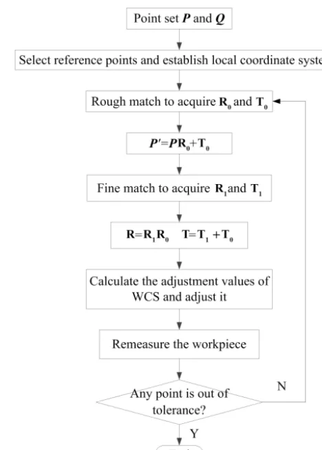
Figure 1.The procedure of stepwise matching process.
Step 1.Select 3 pairs of corresponding points as the ref-erence points in the P andQ point sets respectively, and establish actual and theoretical local coordinate systems;
Step 2.Rough matching is achieved by local coordinate systems alignment, and the rough matching matrixesR0and
T0are calculated by the coordinate systems alignment;
Step 3.Actual point setP is translated intoP0through the
rough matching matrixes;
P0=PR0+T0 (1)
Step 4.The SADE algorithm is adopted to search for the fine matching matrixesR1andT1ofP0relative toQ;
Step 5.Calculate the total transformation matrixesRand
TfromR0,R1,T0andT1;
R=R1R0
T=T0+T1 (2)
Step 6.Calculate the adjustment values of WCS and adjust it;
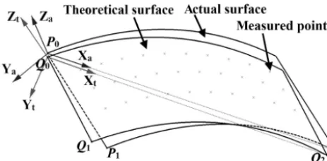
Figure 2.The local coordinate systems.
2.1 The construction of the local coordinate systems
As shown in Fig. 2, the posture errors exist between the the-oretical and the actual surfaces. In order to establish the local coordinate systems, 3 pairs of measured points on the the-oretical surface and the actual surface are respectively se-lected as the reference points. In general, the points are non-collinear, and they should be distributed on the measured sur-face as far as possible outside the other points, such as corner point and so on. According to the reference points, the unit axis vectors of the local coordinate systems can be calcu-lated.
The theoretical and actual local coordinate systems are de-fined asQ0−XtYtZtandP0−XaYaZarespectively. Define
the axial vectors of actual local coordinate systems asia,ja
andka,P0as the origin; define the axial vectors of theoretical
coordinate systems asit,jtandkt,Q0as the origin. Then
it=
Q2−Q0
Q2−Q0
, kt=
Q1−Q0
Q1−Q0
×it, jt=it×kt
ia=
P2−P0
|P2−P0|
, ka=
P1−P0
|P1−P0|
×ia, ja=ia×ka
(3)
2.2 The solution of the rough matching matrixes
The rough matching is completed through the alignment be-tween the local coordinate systems. After the rough match-ing,P0−XaYaZacan coincide withQ0−XtYtZtcompletely.
The relation between local coordinate systems and the rota-tion matrixR0is expressed as Eq. (4) (Yan et al., 2004).
it jt kt T = ia ja ka T R0 R0
=h cosγ0cosβ0 cosβ0sinγ0 −sinβ0
sinα0sinβ0cosγ0−cosα0sinγ0 sinα0sinβ0sinγ0−cosαcosγ0 sinα0cosβ0
cosα0sinβ0cosγ0+sinα0sinγ0 cosα0sinβ0cosγ0−sinαcosγ0 cosα0cosβ0
i
(4)
Where the α0, β0,γ0 represent the orientation angle from
P0−XaYaZa andQ0−XtYtZt respectively, which can be
expressed in Eq. (5).
α0=arctan
R0(2,3)
R0(3,3)
β0=arctan
−R0(1,3)
p
[R0(2,3)]2+[R0(3,3)]2
γ0=arctan
R0(1,2)
R0(1,1)
(5)
WhereR0(i, j) (i, j=1, 2, 3) represents the value of theith
row and thejth column of the matrixR0.
The points P0 and Q0 are the centroid of the point set
P andQrespectively, and the translation matrix can be ac-quired by Eq. (6).
T0=
1
n n
X
i=1
Qi−1 n
n
X
i=1
PiR0=
tx0 ty0 tz0 (6)
The rough posture errors between the theoretical and the ac-tual surfaces can be described by the rough posture error ma-trixPE0in Eq. (7).
PE0=
α0 β0 γ0
tx0 ty0 tz0
(7)
2.3 The solution of the fine matching matrixes
Define the fine matching rotation matrix asR1 (its form is
similar toR), and the translation matrix as T1 (its form is
similar to T). According to the similar definition, the fine matching matrixes parameters includes the orientation angles
α1,β1,γ1and the translation valuestx1,ty1,tz1.
2.3.1 The objective function
After the rough matching, actual measured point set P is converted toP0, which is denoted asP0= {Pi0|i=1, . . ., n}. The fine matching is to search for the optimal transformation
R1 andT1, and make the point setP0 be close toQin the
range of tolerance. Generally, the matching result is evalu-ated by the distance between the point setQandP0. So the
fine matching can be summed up as a minimization problem, and its objective function can be defined as Eq. (8).
f(R1,T1)=
1 n n X i=1
Qi− P0iR1+T1
2
2 (8)
From Eq. (8), it is obvious that the objective function belongs to nonlinear problem. In order to improve the computational efficiency, it is necessary to reduce the dimension of the ob-jective function. According to Eq. (6), the Eq. (8) can be ex-pressed as follows
f(R1)=
1
n n
X
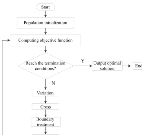
Figure 3.The procedure of the SADE algorithm.
Qi− P0iR1+
1
n n
X
i=1
Qi− 1 n
n
X
i=1
P0i ! R1 ! 2 2 (9)
Then the objective function can be defined to search the op-timal orientation angles to minimizef(R1).
2.3.2 Optimization operation
In this paper, the objective function can be solved by the SADE algorithm, which is developed based on the basic dif-ferential evolution algorithm. The difference between them is the self-adaptive variation operator and crossover operator can be designed in the SADE algorithm. Therefore, it can not only avoid low search efficiency and poor global optimal so-lutions caused by the overlarge variation rate, but also avoid the low population diversity and prematurity caused by the too small variation rate (Tasoulis et al., 2004). Figure 3 is the procedure of the SADE algorithm.
The self-adaptive variation operator F can be defined in Eq. (10), which controls the amplification of deviation vari-ables (Tasoulis et al., 2004; Storn and Price, 1997).
F =2e 1− Gm
Gm+1−G
F0 (10)
Where F0 is the initial variation operator,Gmis the
maxi-mum evolution generation, andGrepresents the current evo-lution generation.
At the start of computation process, set G=1 andF =
2F0.F is large which can keep the individuals diversity and
avoid the prematurity. As the process progresses,F is gradu-ally decreased which is close toF0at the end. It will increase
the probability of searching for the global optimal solutions.
The self-adaptive crossover operator CR can be defined in Eq. (11),
CR=CRmin+
G(CRmax−CRmin)
Gm
(11)
where CRminis the minimum crossover operator and CRmax
represents the maximum one.
Generally, the larger the value of CR is, the more prone cross. When CR is small, it can maintain the diversity of the population and global search. According to Eq. (11), CR gradually increases asGincreases. Therefore, at the begin-ning of the computation process, population diversity can be better guaranteed and global search can be performed. Then, the local search ability can be enhanced to improve the accu-racy of the algorithm.
Through the rough matching, the posture error between theoretical and actual surface is decreased greatly. Theoret-ically, the ranges ofα1, β1 andγ1 cannot exceed the
cor-responding value of α0, β0 andγ0, i.e., the rough
match-ing determines the boundary values of the subsequent opti-mization variables approximately. By taking into account the rough matching error, their ranges can be enlarged appropri-ately. Therefore, the ranges ofα1,β1andγ1can be defined
as [−α0−k1,α0+k1], [−β0−k2,β0+k2] and [−γ0−k3,
γ0+k3] respectively, whereki(i=1, 2, 3) are constants.
3 Adjustment values of the machine tool
Through the matrixesR and T, according to the structure type of the 5 axis machine tools, the adjustment values can be solved, including rotation angles and translation values of each axis. With swivel, frame or inclined plane machin-ing functions, the localization of WCS is defined by some specific feed axis movement (HEIDENHAIN, 2011; SINU-MERIK, 2009). They can be calculated by the matching ma-trixes and topology of machine tool.
The WCS translation can be realized by the movement val-uesSX,SY,SZ ofx,yandzaxis. In addition, the WCS
ori-entation can be defined by the rotation of rotary axis. Taking 5 axis machine tool of XFYZBA topology (which has two rotary axes in the head) as an example, the orientation can be defined by the rotation anglesSA,SBofaandbaxis.
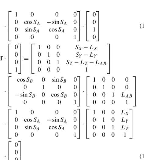
Taking worktable as reference, the WCS origin point and orientation can be described by integrated geometric model of 5 axis machine tools, registration matrixTandR. The ad-justment values can be deduced as following, which is based on the inverse kinematical transformation theory (Zhu et al., 2012): R· 0 0 1 0 =
cosSB 0 sinSB 0
0 1 0 0
−sinSB 0 cosSB 0
0 0 0 1
Figure 4.The model of S-shaped workpiece.
Figure 5.The initial posture of the workpiece.
·
1 0 0 0
0 cosSA −sinSA 0
0 sinSA cosSA 0
0 0 0 1
· 0 0 1 0 (12) T· 0 0 0 1 =
1 0 0 SX−LX
0 1 0 SY−LY
0 0 1 SZ−LZ−LAB
0 0 0 1
·
cosSB 0 sinSB 0
0 1 0 0
−sinSB 0 cosSB 0
0 0 0 1
·
1 0 0 0
0 1 0 0
0 0 1 LAB
0 0 0 1
·
1 0 0 0
0 cosSA −sinSA 0
0 sinSA cosSA 0
0 0 0 1
·
1 0 0 LX
0 1 0 LY
0 0 1 LZ
0 0 0 1
· 0 0 0 1 (13)
where (0, 0, LAB) are thea axis origin coordinates in the baxis coordinates system, (LX,LY,LZ) are the cutter
loca-tion point coordinates in theaaxis coordinates system.
4 The application and comparison experiment
Because the accuracy of aviation structural part is suscep-tible to the machining process complexity and error fac-tors, the need for machining localization adjustment is more urgent. As representative of typical aviation structure part, an S shape test piece from ISO test conditions for ma-chining centers was applied to verify the proposed method (ISO CD 10791-7, 2017). It includes one plane, two cylin-drical holes and two ruled surfaces, whose machining toler-ances are±0.035 mm, and the WCS is defined by reference planesA,B andC, as shown in Fig. 4. The initial posture of the machined surface is shown in Fig. 5. All the measured points (40 points) are overcut or undercut, and the average over tolerance is about 1.8797 mm.
4.1 The rough matching
Firstly, the machined surface of the workpiece is measured to acquire the theoretical measured point setQ. Then 3 pairs of reference points are selected to establish the local coordi-nate systems, as shown in Table 1, and the rough matching matrixes are shown in Table 2.
4.2 The fine matching
After the rough matching, the approximate boundary val-ues can be determined based onPE0asα1∈ [−5,5◦],β1∈
[−5.5,5.5◦],γ1∈ [−3,3◦].
According to the objective function and the optimization variables, relevant parameters of the SADE algorithm are de-termined. The reasonable value ofNPis selected between 5D
and 10D(NPis the population size andDis the dimension
of the variable), and a good initial value of variation operator
F is between 0.5 and 0.8 (Storn and Price, 1997).In this pa-per,Dis 3, andNP is 30, so the initial variation operatorF0
can be selected between 0.25 and 0.4.Gmis generally in the
Table 1.The local coordinate systems of the rough matching.
The coordinates of reference points The direction vectors of local coordinate systems
Q0 (278, 197.5, 40) it (−0.7847, 0.1537, 0.6005)
Q1 (284, 197.5, 0) jt (−0.6072, 0.0041,−0.7945)
Q2 (32, 2.5, 40) kt (−0.1246,−0.9881, 0.0901)
P0 (275.6396, 200.0118, 28.3149) ia (−0.7795, 0.1274, 0.6133)
P1 (278.4501, 202.1547,−11.9779) ja (−0.6159, 0.0231,−0.7875)
P2 (33.0333, 1.0147, 37.4418 ) ka (−0.1145,−0.9916, 0.0605)
Table 2.The rough matching matrixes.
R0
0.996765498 −0.013322882 0.079253025 0.017398606 0.998549102 −0.050960562 −0.0784591 0.052174622 0.995551093
T0 1.993530992 −0.02664576 0.158506049
PE0
−2.930315 −4.545631 −0.765776
1.993531 −0.026646 0.158506
Table 3.The fine matching matrixes of the SADE algorithm.
R1
0.999999987 4.47×10⁻⁵ −0.000153907 −4.48×10⁻⁵ 0.999999862 −0.000522559 0.000153883 0.000522566 0.999999852
T1 0.337889015 0.037944696 −0.072290709
PE1
0.030363 0.003006 −0.003109 −0.025868 −0.026018 0.032532
Table 4.Adjustment values of machine tool.
R
0.996778338 −0.013286276 0.079097524 0.017394967 0.998522297 −0.051484338 −0.07829661 0.052694372 0.995536511
T
2.331420007 0.011298935 0.086215339
Rotation angles SB SA Translation values SX SY SZ
4.543◦ 2.951◦ 43.163 mm −26.566 mm −2.218 mm
Figure 6 is the optimization curve of SADE algo-rithm. After 200 iterations, the global optimal solutions can be obtained (α1= −0.0299◦, β1=0.0088◦, γ1=0.0026◦,
f(R1)=0.1148 mm). The fine matching matrixesR1andT1
are shown in Table 3.
4.3 The adjustment of the machine tool
The final rotational and translational transformation matrixes
R andT can be solved by Eq. (2). The adjustment values of the machine tool are listed in Table 4. According to the values, the workpiece posture is adjusted with WCS.
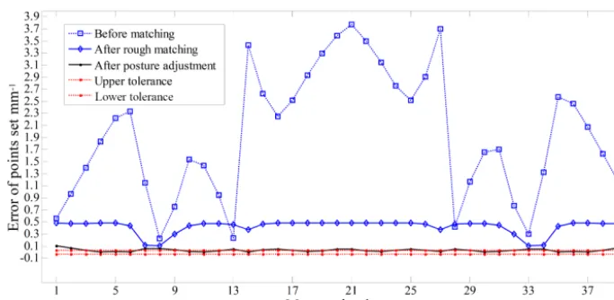
Figure 7 shows the error distribution of measured points which represent before the matching, after rough matching and posture adjustment. ComparingPE1withPE0, it is
ob-vious that the error between the theoretical and actual posture is decreased greatly. Through posture adjustment, none of the measured points is out of tolerance.
In order to verify the effectiveness of the method proposed, a comparison with other localization algorithm is conducted. The algorithm consists of rough surface matching and accu-racy surface matching, and genetic algorithm-simplex (GAs) are introduced in the step of accuracy surface matching (Yan et al., 2004).
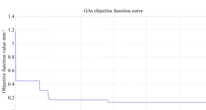
Figure 8 is the optimization curve of GAs. The global opti-mal solutions are obtained after 600 iterations (α1=0.0096◦,
β1=0.0074◦, γ1=0.0607◦, f(R1)=0.12812 mm).
Fig-ure 9 is the error distribution of measFig-ured points after postFig-ure adjustment by GAs, and there are 10 measured points which are still over tolerance.
Figure 6.Optimization curve of the SADE algorithm.
Figure 7.The errors of point set before and after posture adjustment by the SADE algorithm.
Figure 9.The errors of point set before and after posture adjustment by the GAs.
5 Conclusion
In order to solve the problem about non-uniform allowance distribution in precise machining process, this paper devel-ops a stepwise matching method based on contact measured point sets for workpiece posture adjustment. The stepwise matching includes the rough and fine matching processes. After matching, the spatial transformation matrixesR,Tand the adjustment values of machine tool can be obtained accu-rately. At last, some experiments were presented to demon-strate the performance of the method.
Appendix A
Q Theoretical point set
P Actual point set
ia,ja,ka Axial vectors of actual coordinate system
it,jt,kt Axial vectors of theoretical coordinate system
P0 Actual point set after rough matching P00 Actual point set after fine matching R0 Rough matching rotation matrix
T0 Rough matching rotation matrix
R1 Fine matching rotation matrix
T1 Fine matching translation matrix
R Final rotation matrix
T Final translation matrix
PE0 Rough posture error matrix
Author contributions. LJ and YL designed the experiments. KT and YF carried the experiments out. YL developed the model code and performed the simulations. LJ prepared the manuscript with contributions from all co-authors. YZ and SM revised the manuscript.
Competing interests. The authors declare that they have no con-flict of interest.
Acknowledgements. This work is supported by the Special Fund of High-end CNC Machine Tools and Basic Manufacturing Equipment (2015ZX04001002), China.
Edited by: Lotfi Romdhane
Reviewed by: two anonymous referees
References
Dai, Y., Chen, S., Kang, N., and Li, S.: Error calculation for correc-tive machining with allowance requirements, Int. J. Adv. Manuf. Tech., 49, 635–641, https://doi.org/10.1007/s00170-009-2437-5, 2010.
Du, S., Liu, J., Bi, B., Zhu, J., and Xue, J.: New iterative clos-est point algorithm for isotropic scaling registration of point sets with noise, J. Vis. Commun. Image R., 38, 207–216, https://doi.org/10.1016/j.jvcir.2016.02.019, 2016.
Evgeny, L., Dmitry, C., and Aniko, E.: Pre-registration of arbitrarily oriented 3D surfaces using a genetic algorithm, Pattern Recogn. Lett., 27, 1201–1208, https://doi.org/10.1016/j.patrec.2005.07.018, 2006.
Ge, X. M. and Thomas, W.: Surface-based matching of 3D point clouds with variable coordinates in source and target system, ISPRS J. Photogramm., 111, 1–12, https://doi.org/10.1016/j.isprsjprs.2015.11.001, 2016.
HEIDENHAIN: iTNC 530 operation Manual V6, vol. 12, HEI-DENHAIN, Traunreut, Germany, 2011.
ISO CD 10791-7: Test conditions for machining centres-Part 7: Accuracy of finished test piece, ISO CD 10791-7, International Organization for Standardization (ISO), Geneva, Switzerland, 2017.
Ma, Y., Guo, Y., Lei, Y., Lu, M., and Zhang, J.: Efficient ro-tation estimation for 3D registration and global localization in structured point clouds, Image Vision Comput., 67, 52–66, https://doi.org/10.1016/j.imavis.2017.09.003, 2017.
Maier-Hein, L., Franz, A. M., Santos, T. R. D., Schmidt, M., Fangerau, M., and Meinzer, H. P.: Convergent iterative closest-point algorithm to accommodate anisotropic and in homoge-nous localization error, IEEE T. Pattern Anal., 34, 1520–1532, https://doi.org/10.1109/tpami.2011.248, 2012.
Maiseli, B., Gu, Y., and Gao, H.: Recent developments and trends in point set registration methods, J. Vis. Commun. Image R., 46, 95–106, https://doi.org/10.1016/j.jvcir.2017.03.012, 2017. Mehrad, V., Xue, D., and Gu, P.: Robust localization to align
mea-sured points on the manufactured surface with design surface for freeform surface inspection, Comput. Aided Design, 53, 90–103, https://doi.org/10.1016/j.cad.2014.04.003, 2014.
SINUMERIK: 5-axis machining Manual, vol. 05, SINUMERIK, Erlangen, Germany, 2009.
Srinivasan, H., Harrysson, O. L. A., and Wysk, R. A.: Auto-matic part localization in a CNC machine coordinate system by means of 3D scans, Int. J. Adv. Manuf. Tech., 81, 1127–1138, https://doi.org/10.1007/s00170-015-7178-z, 2015.
Storn, R. and Price, K.: Differential Evolution-A Simple and Effi-cient Heuristic for Global Optimization over Continuous Spaces, J. Global Optim., 11, 341–359, 1997.
Sun, Y., Wang, X., Guo, D., and Jian, L.: Machining localiza-tion and quality evalualocaliza-tion of parts with sculptured surfaces us-ing SQP method, Int. J. Adv. Manuf. Tech., 42, 1131–1139, https://doi.org/10.1007/s00170-008-1673-4, 2009.
Tan, G., Zhang, L., Liu, S., and Ye, N.: An unconstrained ap-proach to blank localization with allowance assurance for ma-chining complex parts, Int. J. Adv. Manuf. Tech., 73, 647–658, https://doi.org/10.1007/s00170-014-5798-3, 2014.
Tang, W., Li, Y., Yu, J., Zhang, J., and Yu, L.: Locating error anal-ysis for workpieces with general fixture layouts and parame-terized tolerances, P. I. Mech. Eng. B-J. Eng., 230, 416–427, https://doi.org/10.1177/0954405414551075, 2016.
Tasoulis, D. K., Pavlidis, N. G., and Plagianakos, V. P., and Vrahatis, M. N.: Parallel Differential Evolution, Evol. Comput., 2, 2023– 2029, https://doi.org/10.1109/cec.2004.1331145, 2004. Wang, P., Li, S., Zhang, D., and Li, Y.: The machining error
control of blade shape based on multivariate statistical pro-cess control, P. I. Mech. Eng. B-J. Eng., 229, 1912–1924, https://doi.org/10.1177/0954405414540648, 2015.
Yan, S. J., Zhang, Y. F., Peng, F. Y., and Lei, X. D.: Research on the localization of the workpieces with large sculptured sur-faces in NC machining, Int. J. Adv. Manuf. Tech., 23, 429–435, https://doi.org/10.1007/s00170-003-1897-2, 2004.
Zhang, D. H., Zhang, Y., and Wu, B. H.: Research on the adaptive machining technology of blisk, Adv. Mat. Res., 69–70, 446–450, https://doi.org/10.4028/www.scientific.net/amr.69-70.446, 2009. Zhu, L. M., Xiong, Z. H., Ding, H., and Xiong, Y. L.: A distance function based approach for localization and profile error evalu-ation of complex surface, J. Manuf. Sci. E.-T. ASME, 126, 542– 554, https://doi.org/10.1115/1.1763186, 2014.