A Lightweight Routing Protocol for a Wireless Video
Surveillance Platform: Implementation,
Experiments and Perspectives
Saadi Boudjit
1,∗, Anis Harfouche
2, Azeddine Beghdadi
11Université Paris 13, Laboratoire L2TI, 99 Av J-Baptiste Clément, 93430 Villetaneuse, France 2ESI – Ecole nationale Supérieure d’Informatique, 16309 El Harrach Algiers, Algeria
Abstract
Recently, a new application of wireless sensor networks has emerged and it consists on Multimedia Surveillance Wireless Sensor Networks (MSWSNs). This application involves interconnected wireless video sensors capable of processing, sending, and receiving data. The first step in this work is to setup a efficient wireless video surveillance system to help elders who need assistance while they prefer still living in their houses. The objective is to early detect and transmit via Internet any abnormal behavior or domestic accident to assistance services. For this, small cameras embedded on wireless home deployed sensors have been considered. Moreover, a lightweight routing protocol for an optimized data transmission has been proposed. The whole system was implemented on an Arduino based platform on which a set of experiments were conducted. The second step in an ongoing work is to extend our experiments to a safety wireless video surveillance platform in an urban and public environments.
1. Introduction
Nowadays, the number of elderly people keeps growing and represents a non negligible part of the global population in the world. Indeed, 8.2% of global population in the world are beyond 65 years old [1] and number of them require more or less home intensive monitoring. On an other hand, receiving those ageing people who need assistance in dedicated infrastructures with qualified staffcosts a lot of money either for them and for governments. Also, a large number of elderly prefer continue to live in their own houses rather than joining those healthcare centers. In this last case, However, they could be subject to domestic accidents and the latters are often detected after a while. Hence, platforms for remote monitoring of elders may be of interest at different levels. First, it would allow ageing people to stay home which may have an important impact on their state of mind, a very important element in case of recovery or chronic diseases. Secondly, those platforms are cost effective and use either Bluetooth [2]
∗
Corresponding author. Email:[email protected]
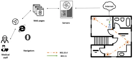
or ZigBee [3] based radio transmissions to exchange data. In most cases, however, ZigBee is preferred because of its low energy consumption due to the possibility to put the radio in the sleep mode. As depicted in Figure 1, such platforms are usually composed of sensors with embedded cameras and coordinators called sinks which collect pictures from the network and transmit them to remote databases servers. Sinks are generally linked to a computer or a smartphone/PDA that offer them different transmission technologies for Internet access (WiFi/3G/4G). Pictures on these databases servers can be accessed through simple browsers to allow monitoring staff to have a continuous view of elders environments.
This paper presents our platform details that can be deployed in a common house, permitting the monitoring of several areas (rooms, kitchen, garden, ...) at the same time, by using small non-intrusive devices which route collected data towards sinks. The paper is organized as follows. In section 2, we will present and discuss some previous works related to remote monitoring through WSNs in general and Wireless Multimedia Sensor Networks (WMSNs) in particular.
on
Ambient Systems
Research Article
Keywords: Social goods, healthcare, safety, communication
Copyright© 2017 Saadi Boudjit etal., licensedto EAI. Thisisanopen access articledistributedunderthetermsofthe Creative Commons Attribution license (http://creativecommons.org/licenses/by/3.0/), which permits unlimited use,
distribution and reproduction in any medium so long as the original work is properly cited. doi:10.4108/eai.17-5-2017.152548
In section 3, we will give more details about our own contribution and some of its key parts. The implementation details of the proposed architecture are presented in section 4. Section 5 highlights some improvements that can be brought to our contribution as long as future planned works and perspectives. Section6concludes the paper.
2. Related work
Several works on remote monitoring have been proposed in the literature either for health purposes or for safety checking especially for a specific category of persons as elders. The majority of them use scalar sensors embedded on those persons or setted in their environment to collect simple measures as temperature, heartbeat, blood sugar or brain activity. In Oslo University Hospital, researchers implemented and tested a Biomedical Wireless Sensor Network (BWSN) [4] where they integrated six different types of sensors; Wireless Pressure Transducer, DigiVent Pulmonary Air Leakage, CardioPatch ECG sensor, Medical UWB-IR radar, Heart Monitoring Accelerometer, SpO2 & Temperature sensors. Patients which got these sensors could keep a good mobility and met a shorter hospital stay period than usually with this procedure.
In [5] and [6], a system prototypes that provide distance healthcare at home have been proposed. These systems automatically measure and collect home and body parameters and transmit them to a central server through a public network. The central server analyses retrieved data to form reports about elder’s activity and health state, and in case of emergency, automatically sends an alarm to assistance services through voice phone calls, SMS or E-mails.
However, works where monitoring platforms use multimedia aspect are fewer. In [7], the architecture of a monitoring platform based on WMSN is proposed. The monitored persons are equipped with smartphones to be localized by a program agent and the latter sends the localisation to image, sound and depth based sensors deployed in the environment. The sensors start to track the persons and send data back to the agent. The agent uses machine learning techniques based on usual behavior of those persons to detect any abnormal behavior and launches alerts destined to monitoring staff. For the best of our knowledge no complete implementation of this platform has been made. Moreover, the use and processing of machine learning techniques need a non negligible period of time which will impact the real time aspect of the platform.
Another platform proposed in [8] allows to detect some basic events by making images processing at sensor level. Two consecutive images are compared in order to identify a simple behavior. For example, the
sensor is able to detect the event of leaving a room by first noticing nobody in front of the door in a picture followed by a picture with a person in door step and finally a last picture with nobody in front of the door. Obviously, these kind of platforms may be useful only for detecting simple events and would meet more difficulties with more complex events as human falls.
3. Our contribution
For our solution, we considered the scenario of ageing people living in a house with several areas. For this scenario, several sensors are deployed to maintain a good coverage of all the areas where these people can be and the deployed sensors meet low mobility during network’s lifetime. Moreover, we considered a multi-hop sink rooted tree topology for data transmission. Indeed, due to radio range restrictions imposed by ZigBee technology, some sensors may be too far from the sink for a direct data transmission. Therefore, we have proposed a multi-hop routing algorithm which gives the possibility to remote nodes without direct links with the sink to transmit their data to the latter through multi-hop. The general architecture of the proposed system is presented in Figure1. Sensor nodes exchange data with the sink which has in addition to its ZigBee interface, a WiFi interface for Internet access without the need for a PC or a PDA. Information about taken pictures are stored in a remote database server and the pictures themselves are stored in a remote file server. This allows the web application we developed, to answer requests coming from end users asking for last pictures related to a specific monitored person. The web application gets information about stored pictures from the database server and then, requests them from the file server. Due to sensor’s low calculating capabilities, we are not proposing any image processing made on sensors level. Any processing on pictures can be done at servers level which offer greater processing abilities.
Figure 1. General Platform Architecture
3.1. Data exchange within the network
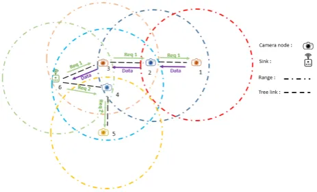
use generic ’Hello’ and ’Topology control’ packets to maintain the topology as it is the case in some known ad hoc routing algorithms for sensor networks: CTP [9], MintRoute [10] or MultiHopLQI [11]. The discovery of the whole topology is realized at the initialization phase made at the beginning of the platform deployment. This may help to save network bandwidth and reduce its energy consumption. We propose a sink driven routing protocol to build a sink-rooted tree topology of the network. The sink is the only node that identifies all camera nodes present in the network and it is responsible of sending requests periodically to each camera node in order to ask for a picture. Each camera node has only a local view of the topology which helps it to route data coming from neighborhood towards the sink and requests coming from the sink towards other camera nodes (Figure2).
Figure 2. Example of a tree topology
When camera nodes get launched for the first time, they start to broadcast signed signalisation packets to join the network. This first phase is called Signalisation Phase and it’s pseudo-code is given in Algorithm-1. When a camera node receives a signalisation packet from an unknown source, it records the source address of the packet and the one of the node the packet have been relayed from (next hop to the source), then it broadcasts the packet itself. If it receives, however, a signalisation packet generated by an already known source but relayed by a different next hop node, it stores the source address and the new next hop address in an alternate table that would be useful in case of old next hop node failure. Two modes may be used, the simplest one is to put the first received couple (camera node address, next hop towards it) in the routing table and to store other later discovered routes towards this camera node in the alternate table. A smarter mode, even if it requires more processing, would be to keep in the routing table the link which has the best RSSI (Radio Signal Strength Indicator) and classify other links according to this metric in the alternate table.
Algorithm 1: Camera node Signalisation Phase
1: While (Signalisation Timer) 2: Broadcast signalisation
3: if(Received signalisation packet)
4: # source node & relay node refer to the packet 5: if(Unknown source node)
6: Add_route(source node , relay node) 7: elseif(Unknown (source node , new relay node)) 8: Add_alternate(source node , new relay node) 9: relay node = me
10: Broadcast the packet
After a period of time, all camera nodes which are not isolated from the network (out of range of all other nodes) are listed at the sink level. The sink keeps the destination address of each known camera node in the network and the next hop to reach it. The next hop is the node address from which the signalisation packet of the destination address have been received. The sink signalisation phase is exactly the same as for camera nodes except that the sink doesn’t broadcast the signalisation packets it receives.
We use at each camera node a routing table to route requests and data packets. An entry of the table contains the address of a camera node, next hop to reach it and next hop to route its data towards the sink. For example, the tables of nodes 2 and 4 in Figure 2 are described in Figure3.
Figure 3. Routing tables
First and second fields of each entry of the table are filled during Signalisation Phase, third field is filled when a sink request is received. A similar table is used at the sink with only the first and second fields, the third being useless.
Algorithm 2: Sink Collection Phase
1: if(Cycle Timer Expires)
2: foreach:CN in RoutingTable 3: Send request to CN 4: Wait for data from CN 5: if(receiving data)
6: while(receiving data)
7: Concatenate in SD file 8: Upload file’s data to database 9: Upload file to FTP server 10: elseif(timer expires)
11: if(NbRetransmissions reached) 12: if(alternate route exists) 13: Swap it to routingTable
14: else
15: Retransmit request packet
16: Go to 5
At the reception of a request packet, a node verifies if it is addressed to it. If it isn’t, it records the address of the node from which it got the request, this one will be the next hop towards the sink for data packets coming from the camera node specified as destination address in the request packet. Then, this intermediate node forwards the request packet to the next hop it has recorded during Signalisation Phase towards the destination camera node. When receiving a request packet addressed to it, a camera node takes a picture and starts to send data packets to sink via the node it got the request packet from. This way, request packet and data packets follow the same route (in opposite directions) for each camera node.The pseudo-code of this process is given in Algorithm-3.
If the sink (respec. a camera node) generates (respec. forwards) a request without getting back data after a period of time, it retransmits the request packet. If after several attempts no data packet is received, it suspects a failure of the next hop. If a route towards the same destination camera node is found in the alternate table, it replaces the one in the routing table and get deleted from the alternate table. If no alternate route is found, the request packet is locally dropped. In Figure 4, we give an example of the backup scenario at sink level in case of failure of the node 3 in Figure2.
The packets transiting in the network have all the same structure, as in Figure-5. The field ID_PCK represents the type of the packet which might be a signalisation, request or data packet. Sender field contains the address of the node which sends the packet and this one may be different from the source node of the packet which is specified in the third field. The size field contains the number of bytes of the payload, it is equal to zero except for data and request packets. Indeed, for the request packets, payload field is used to specify the destination of the packet (camera node concerned by the request).
Algorithm 3: Packet Processing at Camera Node
1: if(Received packet via a relay node) 2: switch(packet type)
3: Request:
4: # Source & relay & destination refer to the packet 5: if(destination == me)
6: Take snapshot
7: Send fragments to the source via relay node 8: else
9: NHS = relay in routingTable where CN == destination 10: Forward request to NHC in routingTable where CN ==
destination
11: if(timer expires)
12: if(NbRetransmissions reached) 13: if(alternate route exists) 14: Swap it to routingTable
15: else
16: Retransmit request packet
17: Go to 11
18: Data:
19: Forward to NHS in routingTable where CN == source
Figure 4. Sink’s routing and alternate tables
Figure 5. Common structure of the packets
3.2. Picture’s remote display
Figure6. The second operation for the sink is to upload the picture to the FTP server.
Figure 6. Data conceptual model
When a user asks through a web application for pictures related to a specific person, a request is addressed to the database to get all file names of pictures related to this person. For each file name, the picture is retrieved from the FTP server and then displayed. The user can address more detailed requests by specifying an interval between two dates or by asking only for pictures of a specific area of the monitored structure.
4. Implementation
We have implemented the previously described archi-tecture and the obtained platform stands on two majors parts, the network environment deployed in monitored infrastructure and the servers environment reachable through Internet/LAN network.
4.1. Network environment
The sensors used in our platform are Arduinos Mega 2560 equipped with cameras. We used TTL Serial cameras and Wireless proto Shields with XBee S1 senders to handle ZigBee transmissions between camera nodes. It was possible for us to use a 32 bits long addresses for the nodes, however, due to the nature of the use case of our platform we opted for 16 bits addresses. The sink doesn’t integrate a camera but has a Wireless WiFi Shield to connect to an access point and upload collected data into servers. This shield contains a MicroSD slot which is used by the sink to store a picture while the fragments composing it are being received. When a picture is fully received, the sink transmits its information to remote database and then uploads it into remote FTP server.
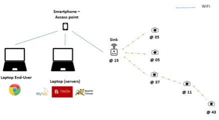
We tried several scenarios for our network topology to retrieve pictures from nodes up to three hops far from the sink as in Figure7. We used a WiFi LAN to access to remote servers which were running on a laptop. The web browser to access to the web application was used
on an end-user laptop. Finally, a smartphone was used as an access point.
Figure 7. 3-hop network topology
At the initialization phase, the sink connects to the LAN through the access point and creates a connexion with the remote database and FTP servers. After the signalisation phase which runs for 2 minutes, it starts to receive data from camera nodes and to upload it to the servers. We didn’t implement yet node’s failure detection scheme based on alternate tables. The sink detects a non responding node if it doesn’t receive data from it after a period of time following a request transmission, after what, a new request is then retransmitted.
Using NTP to keep a continuous correct time at Arduino level needs too frequent refresh and, hence, consumes more energy. In order to still be able to have the time and the date where pictures have been taken, we use a Python script at servers level to change the file name of a picture to insert time and date of its reception at the server. It also exchanges the ID of the sensor in the file name with an abbreviation of its location, which is more meaningful for the end-user.
4.2. Servers environment
Figure 8. End-user authentication form
After being authenticated, the end-user is redirected to a dashboard containing the whole list of the monitored persons for which he has the access rights (Figure-9).
Figure 9. Authenticated end-user list of monitored persons
When the image of an elderly is picked, last pictures referring to his profile are displayed as in Figure-10. The web page is automatically refreshed in order to continuously display most recent received pictures.
5. Future works and perspectives
By the time we are writing this paper we have identified several ideas for our future work which could improve the performances of our current platform. We also aim to adapt and extend this platform to another large scale deployment which is the video surveillance application in an urban environment.
Figure 10. Last received pictures of a monitored person
5.1. Deployed platform enhancement
As a first improvement for our current platform, it would be interesting to add processing capabilities at sensor level to compare two successive pictures and send only data which allows to construct the latest picture starting from the previous one. This would reduce the quantity of data transmitted over the network and, hence, reduces transmission error rate and energy consumption. Moreover, the implementation at server level of an automatic scheme for dangerous behavior detection such as elderly falls would simplify the monitoring task allowing monitors to handle bigger number of persons at the same time. The automatic program would be responsible of the creation of alerts in case of dangerous event detection. We will also be working on empirical studies to determine the best size of picture frames transmitted within the network to achieve the best delivery delay. It would also be interesting to consider the use of such multimedia sensors as long as scalar sensors; the two types being complementary for a global health and safety monitoring. Finally, it would be interesting for us to test our algorithm on a dedicated platform. Indeed, the use of Arduino sensors even if it simplified the implementation and proved the feasibility of the idea did not provide us with real information about energy consumption and QOS performances that could be reached by our algorithm.
5.2. Large scale deployment
sensors could either detect and record potentially relevant activities and make multimedia streams or reports available for future query or send it on real time to a control centre (Figure 11). In this project, we will propose and evaluate solutions to some of related problems that are crucial in an environment like multimedia surveillance wireless sensor networks. The objective here is to see how to adapt and apply the previously proposed solutions to the environment of large scale multimedia surveillance wireless sensor networks. The main issue of interest is data dissemination between deployed sensors and the control centre. The used routing protocols should enable sensor nodes to transmit the monitored information to the sink either directly or through a collaborative or ad-hoc manner among sensors. In addition, data should be relayed in an energy efficient manner by effectively using the transceiver. This is of utmost importance since transceiver is the biggest power-consuming component in a wireless sensor platform. This problem needs equal attention especially in large-scale applications, as battery replacement might not be possible due to terrain or security conditions as in surveillance applications. Many energy aware routing protocols for WSNs have been proposed in literature. They combine techniques like mobility of the sink, duty cycling, and data aggregation to equally distribute the energy consumption among sensors and hence, improve the network lifetime [12][13]. However, for some applications of multimedia sensor networks like urban video surveillance, a specific attention should be given to the design of the appropriate routing protocols. As depicted in Figure 11, multi-tier network architecture of heterogeneous multimedia sensor nodes could be needed for the purpose of video surveillance. The low-resolution tier can be used for object detection and recognition while sensors in the high-resolution tier can be used to track moving objects. Duty-cycling technique could be used inside a tier but also among tiers to save energy. In this project, we will consider hierarchical routing protocols with respect to the specifications of multimedia wireless sensor networks for video surveillance.
6. Conclusion
In this paper, we have first proposed a routing algorithm for images collection in a WMSN adapted to the specific use case of elders monitoring in domestic areas. Then we have implemented our algorithm in a generic platform based on Arduino Mega 2560 multimedia sensors. The presented solution may be seen as an alternative for regular monitoring platforms based on fixed cameras. It may offer some advantages in terms of mobility, simplicity of network expansion and thus covered area, and continuity of service in
Figure 11. Multimedia Surveillance heterogeneous WSN architecture
case of energy breakdown (power cut off) compared to regular platforms with fixed cameras. Finally, as detailed in section 5, we have identified several ideas for our future works to improve the performances of our current platform but also to extend it to the context of large scale urban wireless video surveillance.
Acknowledgements. This work was made possible by NPRP
grant number NPRP8-140-2-065 from the Qatar National Research Fund (a member of Qatar Foundation). The statements made herein are solely the responsibility of the authors.
References
[1] World population in 2013:
http://www.worldometers.info/fr/population-mondiale/#age, Consulted on June 2016.
[2] Bluetooth Technology - Bluetooth Special Interest Group (SIG), www.bluetooth.com.
[3] Zigbee Alliance - 802.15.4 Standard, www.zigbee.org. [4] Dag A. and Naess E. and Karl Ø. (2010)
Biomedical Wireless Sensor Network, Phase II, https://brage.bibsys.no/xmlui/handle/11250/2389799, Research report, Consulted on June 2016.
[5] Townsend K.A. Haslett J.W.andTsang T.K.K.and El-Gamal M.N.andIniewski K.(2005)Recent Advances and
Future Trends on Low Power Wireless Systems for Medical Applications, Proceedings of the Fifth International Work-shop on System-on-Chip for Real-Time Applications, pp. 476-478.
[6] Boudra H. (2014) Un prototype de système de
télésurveillance médicale basé sur les capteurs et les réseaux de capteurs sans fil, Research report, http://www.archipel.uqam.ca/id/eprint/6035.
[7] Sou-Young J. and Young-Seob J. and Chankyu P.
and KyoJoong O. and Ho-Jin C. (2012) An Intelligent
[8] Al-Marakeby A. (2013) Camera-Based Wireless Sensor
Networks for E-Health, Journal of Advanced Research in Computer and Communication Engineering, Vol. 2, Issue 12, pp. 4757-4761.
[9] Fonseca R.andOmprakash G.andKyle J.andSukun K.
and Philip L. and Alec W. (2009) The collection tree
protocol (CTP), TinyOS TEP 123: 2.
[10] Alec W. andTerence T. andDavid C. (2003) Taming
the underlying challenges of reliable multihop routing in sensor networks, Proceedings of the 1st ACM international conference on embedded networked sensor systems, pp. 14-27.
[11] Tolle G. andLevis P.andBuoadonna P.andAlec W.
and Polastre J. (2007) The MultiHopLQI protocol,
http://www.tinyos.net/tinyos- 2.x/tos/lib/net/lqi. [12] Faheem Y.andBoudjit S.andChen K.(2011)Dynamic
Sink Location Update Scope Control Mechanism for Mobile Sink Wireless Sensor Networks, Proceedings of IEEE WONS 2011 Conference, pp. 171-178.
[13] Faheem Y. andBoudjit S.(2015) Duty-Cycle