Research Article
Design and Analysis of Compact Triple Band Microstrip
Patch Antenna for Multiband Applications
Zaka
U
llah
1, M. Irfan Khattak
1, Qazi M. Ali
1, Ejazul Haq
2, Sheeraz Ahmed
3, Amjad Khattak1
1Department of Telecommunication Engineering,University of Engineering and Technology Peshawar, Pakistan 2 School of Electrical Engineering, Xiamen University of Technology, China
3Iqra National University, Peshawar, Pakistan
1[email protected],2[email protected],
[email protected],3[email protected],4[email protected] 5[email protected]
Abstract
In this article, a novel design of multiband microstrip patch antenna has been presented for multiband applications. The Shirt shape antenna is designed on FR-4 substrate and is fed through 50 ohm microstrip feed line. Two l-shape slots are introduced in antenna for size reduction and to provide multiband characteristics while DGS (defected ground structure) is used to achieve bandwidth enhancement. The simulated results show that the antenna operates in three different frequency bands having resonance frequencies at 4.4GHz, 6.2GHz and 8.5GHz. The antenna exhibits good return loss of -21.1dB @4.4Ghz, -15dB @6.2GHz and -30.5dB @8.5GHz. The proposed antenna has stable radiation patterns and gain values which are 5.3db at 4.4GHz, 5.03dB at 6.2GHz, 5.27 at 8.5GHz. The VSWR is also less than 2 and has good efficiency values at the operating bands 62%, 89% and 93% respectively. The Shirt shape antenna finds its applications in commercial WLAN, Wi-MAX and in Radar application.
Keywords: Shirt Shape, Triple Band Antenna, Micro-strip Patch, WLAN and WI-MAX, Radar Application.
Received on 16 November 2017, accepted on 22 February 2018, published on 22 March 2018
Copyright © 2018Zaka ullahet al., licensed to EAI. This is an open access article distributed under the terms of the Creative Commons Attribution licence (http://creativecommons.org/licenses/by/3.0/), which permits unlimited use, distribution and reproduction in any medium so long as the original work is properly cited.
doi: 10.4108/eai.22-3-2018.154383
1. Introduction
In modern era of wireless communication, the need of compact and miniaturized multi-band antenna is flourishing rapidly. To meet this requirement a microstrip patch antenna is the available possible solution. Microstrip patch antenna has patch mounted on substrate and ground plane on the other side. Microstrip patch antenna can be used in mobile and aerospace applications due to light weight and low power consumption during transmission and reception [1].Although microstrip patch antenna has some limitations like narrow bandwidth and low gain but it has several advantages [2] like low profile,
light weight, compact size, financial feasibility and characteristics of covering multi bands with single structure. To overcome these nominated problems various techniques like increasing height of dielectric substrate, decreasing dielectric constant [3] and using parasitic patches [4] have been used to enhance the BW of the planar antennas.
Antennas play a vital role in communication system design in terms of operational frequencies, cost, weight and size. Allocating a single antenna for every communication frequency band would make the whole design of mobile terminal bulky not only in terms of size but also in terms of its weight. This would also pose questions on the financial feasibility of the system design.The best possible solution to
2
this problem is to design a single microstrip antenna with compact size for various communication bands at the same time [5].
Categories of Multiband Antennas
The research study of multiband antenna can be categorized into: PIFAs, wire Antennas and defected patch and ground antennas [6].Authors of [7,8] have put forward few designs for PIFA with multi communication bands. Introduction of parasitic patches to the conventional microstrip patch antenna is also one of the technique for getting multiband characteristics, where in the main radiating patch works at lower frequency band while the parasitic patches are introduced to work at higher frequencies [9].Authors of [10] have achieved quadruple bands is single planer monopole radiator with low substrate height achieving four communication frequencies and that of [11] have proposed a loop structure mixed with monopole to achieve multi bands for communications.
1.2 Defected Ground Structure (DGS)
Defected Ground Structures (DGS) was introduced to microstrip patch antennas for bandwidth enhancement, multi-band features and size reduction. Many researchers have design microstrip patch antenna with DGS to achieve multiband applications such as slot, Double U-slot, E-Slot, H-slot and other structures [12].
1.3 Related work
Looking at simple microstrip patch antenna for single band operation, Numerous microstrip patch antennas have been proposed by various authors in this literature review. In [13] microstrip patch antenna has been presented which has a peak gain of 3.5db with return loss -30db while in [14] the proposed patch antenna has a gain value of 1.4dB and in return loss of -25dB and in [15] the peak achieved gain is 3.4db
In this article a novel design of triple band microstrip shirt-shape patch antenna has been presented in which the main radiating structure is mounted on FR-4 substrate having dielectric permittivity εr=4.3.Two L-shape slots are etched in the rectangular patch which increases the inductance of the patch, resultantly increasing the electrical length of the antenna which produces multi-band characteristic. So the intent behind this work is to produce a new shirt shape design for the patch antenna having the capabilities of covering multi bands of wireless and radar applications. The proposed shirt shape microstrip patch antenna in this work provides multiband characteristics with small size and wide bandwidth (VSWR < 2). The operating frequencies find its application in C and X Bands.
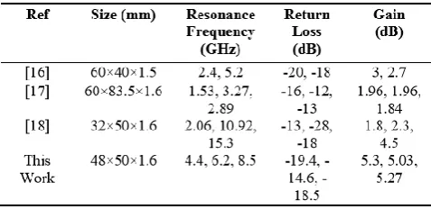
The presented antenna design is also compared with some other works in term if their sizes, frequency bands, return loss and gain values and the results are tabulated in Table 1.
Table 1. Comparison with literature
2 Antenna Design And Theory
As shown in Figure 1, the rectangular patch of dimensions Lp×Wp is mounted on FR-4 𝜀𝑟 = 4.3 and loss tangent of 0.025. Height of substrate is ℎ = 1.6𝑚𝑚. The length and width of substrate (Ls×Ws) is 48mm × 50mm. Dimensions of the truncated ground plane (Lg×Wg) is 48mm×25mm also Defected Ground Structure (DGS) that is circular slot is applied on the ground plane of radius R1=6mm. The shirt-shape antenna is excited using a 50Ω microstrip feed line.
The radiating patch has a dimensions of 31mm×38mm. Two L-shaped flipped slots are etched in both side of the patch. Adding slots increase the electrical length of the antenna by adding inductive elements and thereby produces multi-band characteristics.
The dimensions of antenna are calculated from well-known transmission line theory.
The equation used is the design of rectangular patch antenna is listed below:
Step 1st: Determining the width of patch using:
W= 𝑐𝑓0√ 2 𝜀𝑟+1 (1)
Step 2nd: Determining the length of the patch using:
L= 𝐿𝑒𝑓𝑓-2∆𝐿(2)
Where ‘Leff’ can determine by the formula:
L𝑒𝑓𝑓= 𝑐 2𝑓0√𝜀𝑟𝑒𝑓𝑓
(3) Where
C: velocity of light = 3×10⁸m/s εr:Dielectric constant of substrate
𝜀𝑟𝑒𝑓𝑓=𝜀𝑟+1 2 + 𝜀𝑟−1 2 × √(1+(12ℎ 𝑤
))(4)
EAI Endorsed Transactions on Mobile Communications and Applications
Step 3rd :Extension length of the ΔL can be determine by the equation:
a
b
c
Fig. 1. The proposed antenna design (a) Prospective view (b) Front view and (c) Back view
Methodology used for proposed work is depicted in Figure 2.
Fig. 2. Flowchart of presented work
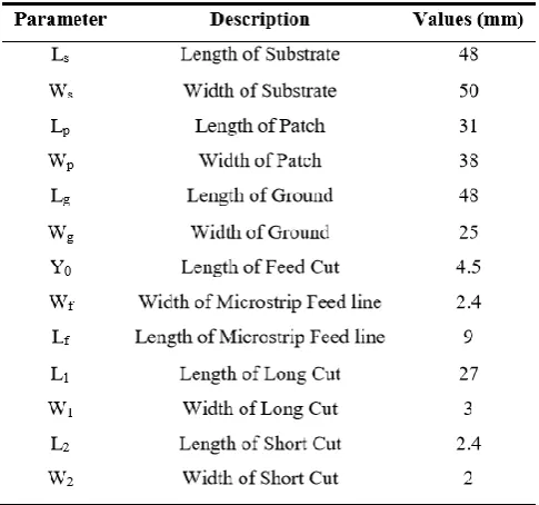
The parameters of the patch, substrate and truncated ground plane are given in Table II.
Table 2. Parameter Values of Proposed Antenna
3 Simulation Results
For performance evaluation purpose the investigated antenna is designed and simulated in CST a 3D simulation design tool. The performance of the proposed antenna is studied in terms of Return loss, impedance matching bandwidth, gain, efficiency, and radiation patterns.
3.1 Return Loss
The depiction in Figure 3 shows that the investigated antenna operates in triple band having resonance frequencies of4.4GHZ, 6.2GHz and 8.5GHz. The minimum achieved reflection coefficient is-30.5 dB at 8.5GHz, 4.4GHz has -21.1dB, while the minimum value is -15dB at 6.2GHz respectively.
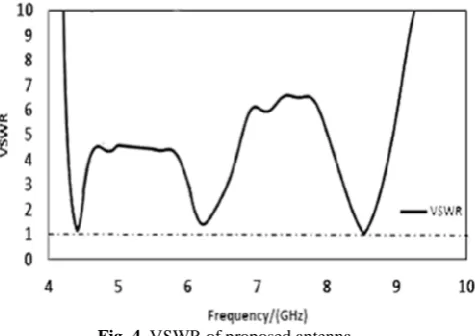
4 3.2 VSWR
The voltage standing wave ratio describe impedance matching of transmission line.In Figure 4, the VSWR <2 at resonance frequencies. At 4.4GHz frequency, the VSWR is 1.1, at 6.2GHzfrequency, VSWR is1.4 and at 8.5GHz frequency, theVSWR value is 1.06.
This is the body text with indent. This is the body text with indent. This is the body text with indent. This is the body text with indent. This is the body text with indent. This is the body text with indent. This is the body text with indent. This is the body text with indent. This is the body text with indent. This is the body text with indent. This is the body text with indent.
Fig. 4. VSWR of proposed antenna
The characteristic parameters of proposed antenna in terms of operating frequencies, return loss, gain,
directivity, bandwidth and efficiency is tabulated in Table 3.
Table 3. Characteristics Parameters of Proposed Antenna
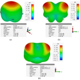
3.3 Gain Pots
a)
b)
c)
Fig. 5. Gain Polar Plot at (a) 4.4GHz (b) 6.2GHz and (c) 8.5GHz
At 4.4GHz, the surface current is dense at the bottom and side arms which mainly contribute to the radiation of the 4.4GHz of the antenna. Moreover, at 6.2GHz surface currents are dense at bottom and feed line and at 8.5GHz the surface currents are dense at the main radiating patch and side arm. The results of current distributions are given in Figure 6
a)
EAI Endorsed Transactions on Mobile Communications and Applications
b)
c)
Fig. 6. Surface Currents at (a) 4.4GHz, (b) 6.2GHz and (c) 8.5GHz
3.5 E-Fields Distribution
At 4.4GHz, E-Field is distributed around the corners and microstrip feed line. At 6.2 GHz E-Field distribution is dense at the arms of the patch while at 8.5GHz E-Field is relatively distributed around the arms and microstrip feed line. The results of E-Field distribution are given in Figure 7 and results of 3D radiations patterns are shown in Figure 8.
a)
b)
c)
Fig. 7. E-Field Distribution at (a) 4.4GHz, (b) 6.2GHz and (c) 8.5GHz
6 4. Conclusion
This article presents a novel shirt-shaped microstrip patch antenna using defected ground structure using single feed. The simulated results show that antenna operates in triple band having return loss < -10dB and better gain values. The return losses are -21.1dB, -15dB, -30.5dB at the frequency 4.4GHz, 6.2GHz and 8.5GHz
respectively. The gain of investigated antenna is 5.3dB, 5.02dB and 5.26dB at the operating resonance frequency. The proposed antenna finds its applications in commercial WLAN, WiMAX for wireless communications and X-band Radar applications.
References
1. Garg, Ramesh. Microstrip antenna design handbook. Artech house, 2001.
2. Targonski, S. D., and David M. Pozar. "Dual-band dual polarised printed antenna element." Electronics Letters 34.23 (1998): 2193-2194.
3. Manohar, Murli, S. K. Behera, and P. K. Sahu. "Bandwidh enhancement with multi-band &multi-polarized rectangular microstrip patch antenna." A Workshop on Advanced Antenna Technology, 2010 Indian Antenna Week. IEEE, 2010.
4. Pozar, David M. "Microstrip antenna aperture-coupled to a microstripline." Electronics letters 21.2 (1985): 4950. 5. Zhang, Ting, et al. "A novel multiband planar antenna for GSM/UMTS/LTE/Zigbee/RFID mobile devices." IEEE Transactions on Antennas and Propagation 59.11 (2011): 4209-4214.
6. Liao, Wen-Jiao, Shih-Hsun Chang, and Long-Kun Li. "A compact planar multiband antenna for integrated mobile devices." Progress In Electromagnetics Research 109 (2010): 1-16.
7. Falade, Oluyemi P., et al. "Single feed stacked patch circular polarized antenna for triple band GPS receivers." IEEE transactions on antennas and propagation 60.10 (2012): 4479-4484.
8. Ur-Rehman, Masood, and Ben Allen. "A compact multi-band slot-ring microstrip patch antenna for wireless applications." Antennas and Propagation Conference (LAPC), 2013 Loughborough. IEEE, 2013.
9. Rowell, Corbett R., and Ross David Murch. "A compact PIFA suitable for dual-frequency 900/1800-MHz operation." IEEE Transactions on Antennas and Propagation 46.4 (1998): 596-598.
10. Usman, M., Jan, M.A., He, X. and Nanda, P., 2016, August. Data Sharing in Secure Multimedia Wireless Sensor Networks. In Trustcom/BigDataSE/I SPA, 2016 IEEE (pp. 590-597). IEEE.
11. Wong, Kin-Lu, Gwo-Yun Lee, and Tzung-Wern Chiou. "A low-profile planar monopole antenna for multiband operation of mobile handsets." IEEE Transactions on Antennas and Propagation 51.1 (2003): 121-125.
12. Hsieh, Hsuan-Wei, et al. "Design of a multiband antenna for mobile handset operations." IEEE Antennas and Wireless Propagation Letters 8 (2009): 200-203. 13. Martinez-Vazquez, Marta, et al. "Integrated planar multiband antennas for personal communication handsets." IEEE Transactions on Antennas and Propagation 54.2 (2006): 384-391.
14. Mukandatimana, MARIE CHANTAL, and Tayeb A. Denidni. "A multi-resonator microstrip-fed patch antenna for broadband dual-band operation." Antennas and Propagation Society International Symposium, 2004. IEEE. Vol. 4. IEEE, 2004.
15. AbuTarboush, H. F., H. S. Al-Raweshidy, and R. Nilavalan. "Triple band double U-slots patch antenna for WiMAX mobile applications." Communications, 2008. APCC 2008. 14th Asia-Pacific Conference on. IEEE, 2008.
16. Werfelli, Houda, et al. "Design of rectangular microstrip patch antenna." Advanced Technologies for Signal and Image Processing (ATSIP), 2016 2nd International Conference on. IEEE, 2016.
17. Karade, Abha R., and P. L. Zade. "A miniaturized rectangular microstrip patch antenna using SSRR for WLAN applications." Communications and Signal Processing (ICCSP), 2015 International Conference on. IEEE, 2015.
18. Subahir, S., et al. "Rectangular spiral microstrip patch antenna integrated with LED for Wifi application." Telecommunication Technologies (ISTT), 2014 IEEE 2nd International Symposium on. IEEE, 2014.
19. Shanmuganatham, T., and Deepanshu Kaushal. "Design of multi utility multi band microstrip calculator shaped patch antenna using coaxial feed." Computer, Communication and Signal Processing (ICCCSP), 2017 International Conference on. IEEE, 2017.
EAI Endorsed Transactions on Mobile Communications and Applications