Dual Axis Sun Tracking Embedded System
Sushant M. Bhasme Prof. Mahendra M. Nayak
M. Tech. Scholar Associate Professor
Department of Electronics and Communication Engineering Department of Electrical and Electronics Engineering PES University, Bengaluru. India PES IT, Bangalore, India
Abstract
The tracking system which can track the sun’s path is necessary to harvest as much as sun’s energy throughout the day. As Sun’s energy is abundantly available free energy in earth, we can make maximum use of such energy. A PCB board for sun tracking system has been developed which suits the application for tracking mechanism. This paper stresses on a unique method used for tracking mechanism. A parabolic sun light collector is being placed in the research lab, which collects the sun light throughout the day to lighten a dark room where sun light is not available. The PCB board designed takes external power supply to power up motors and microcontroller. The PMDC (Permanent Magnet DC) motors are used for the operation. Atmega16 is the main controller for the PCB board designed.
Keywords: RTC, SPA, PMDC, HA_Motor, DEC_Motor
________________________________________________________________________________________________________
I. INTRODUCTION
Modern techniques which involve power generation using fossil fuels, nuclear energy, and coal power etc. are major drawbacks to keep Mother Nature safe. This is the reason behind where every researchers and students gets motivated to take interest in these areas so as to keep develop new ideas which can save nature. Sun light collecting system using solar panels and converting it to electricity was the system which was the best solution developed to make use of sun’s energy. This technology revolutionalised the industry world. The technique was first developed using fixed panels for collecting the sun’s energy. The sun light collecting methods lead the researchers to develop the sun tracking systems to collect maximum sun light by following the path of the sun throughout the day.
Coming to Literature survey, there are many IEEE papers, National and International conference papers, journals presented on Sun tracking systems. A unique technique to track the sun throughout the day to lighten up a dark room has been developed. This unique technique is different from the other sun tracking systems available in market. The tracking system is designed in such a manner that it can be used for solar panels and for lighting system using optical fibers. Paper [1] discusses about the low cost dual axis tracking system developed by researchers to improve the tracking position of the panels to follow the sun’s path. In this paper the sun’s positioning technique is explained. The error in measuring sun’s path with respect to the rotation of motor is demonstrated. Paper [2] discusses about the Mini-dish based solar light collector system. In this paper the researchers have developed the system, which collect the sun light through optical fiber. The structure used is parabolic light collecting system. The sun light is being captured via parabolic reflector and is made to pass through optical fibers. Paper [3] explains a microcontroller based sun tracking system which had two axis rotations. In this system, the researchers used solar panels to harvest the sun light and generate electricity. Microcontroller based automatic tracking was developed in this paper. Paper [4] demonstrates the motor rotation technique for sun tracking system achieving the degree of rotation up to 3.5 degree rotation. This paper illustrates the open loop configuration in which the inputs were RTC (Real Time Clock), SPA (Sun Position Algorithm). Solar panels were used for the operation.
Taking into consideration all the above papers, we have designed our own encoder system for the sun tracking system. The encoder system is explained in the further sections. The tracking mechanism has been developed such that the same mechanism can be used for other robotic purposes and electronic applications. Up to the date, the sun tracking devices available in the market are the automatic trackers, sun trackers using LDR’s (Light Dependent Resistors), Sun trackers using Microcontroller, Fuzzy logic etc. For the current sun tracking system, we are using Microcontroller as the main controller/CPU and the program is being loaded in the same.
The main objective of this paper is to design a PCB board and develop it assembling the required tools. A mechanical structure which is a parabolic sun light reflector is being placed in the research laboratory of PES University, Bengaluru. Since the mechanical structure was lagging with the tracking system, we had to develop the embedded system for the sun tracking purpose. After the completion of the embedded system for sun tracking, the same is being attached to the mechanical structure present for testing purpose and once the testing is being done successfully, the whole mechanical structure with the sun tracking embedded system will be placed on the top floor of the college building. The same will be used for different application purposes. The mechanical structure and the embedded system designed are explained in the further sections.
collector system increases the sun light collection by 40%. In tracking system the parabolic reflector or the solar panels always maintain the perpendicularity with the sun.
The sun tracking systems are divided into two types, open loop tracking system and closed loop tracking system. The following figure illustrates the types of tracking system used worldwide.
Fig. 1: Types of tracking system.
The tracking system used in this paper is open loop, two axis sun tracker system. There are three types of trackers available, which are Horizontal-Axis Tracker, Tilted-Axis Tracker and Vertical-Axis Tracker. The two axis sun tracker, North-South (Elevation), East-West (Azimuth) tracking systems tracks the sun in dual axis so the sun’s vector when normal to the aperture, obtains sun light percentage of 100.
II. BLOCK DIAGRAM
The block diagram depicts the pictorial representation of the sun tracking embedded system developed. In the block diagram, we have used encoder and decoder which are new to the system configurations. The encoder and decoder specification are explained in further sections. The block diagram shows how the power supply is being taken externally. Since we are not going for solar panel, we are taking power supply externally.
As shown in the above figure, two Atmega16 controllers are being used. One is master Atmega16 and other is slave Atmega16 controller. While designing PCB board, we had to consider many parameters which include the proximity sensors placed on mechanical structure and LED drivers and we were running out of ports in master Atmega16, we had to assemble a slave Atmega16 controller. An external 24V DC power supply is required to power up the PMDC motors used. It is controlled by 24V Relay drivers. Two separate PMDC motors are used for North-South (HA_motor) direction and East-West (DEC_motor) direction. There is 5V supply of voltage to Microcontroller and a ground connection. Two motor drivers LMD18245 IC’s have been used for PWM control and direction control. HCTL2022 Decoder is being used for the operation of sun tracking. The whole mechanism of the sun tracking system lies within Encoder and Decoder configuration. Encoder and decoder part is explained in further sections. Proximity sensors are placed on the parabolic mechanical structure. These proximity sensors detect the extreme North, South, East, West situations. LED drivers are used for LED lights; these LED lights will glow for different operations during the sun tracking operation.
Sun Position Algorithm (SPA) is used for the operation purpose. SPA is a sub program, programmed with sun tracking program. Inputs like current time, date, location co-ordinates’ helps to determine the current sun’s position. The mathematical formula includes the precession control of the sun’s movement throughout the day. A predefined time is given as to when the sun tracking program must start. Depending on the Encoder and Decoder values, the whole operation is carried out. The SPA is programmed in Master microcontroller. Slave controller controls the Relay’s and proximity sensors. The master and slave are connected parallel via ports. I2C bus is used for communication between Main controller and RTC (Real Time Control).
Earth rotates 360 degree per day on its axis. On day time earth rotates 180 degree from East in the morning to West in the night. Taking the concept of earth rotation, encoder is being designed. For the encoder to work properly, HCTL2022 decoder is being chosen. As earth rotates 180 degree in day time, for one minute earth rotates 0.25 degree. The sun tracking embedded system is programmed to follow the sun’s path throughout the day using the concept of 0.25 degree per minute movement/rotation programmed using ISR (Interrupt Service Routine) and SPA.
Timer1 is used for ISR, Timer0 and Timer2 are used for PWM signals.
III. ENCODER AND DECODER CONFIGURATION
The whole mechanism of the sun tracking system designed in this paper depends on the encoder and decoder configuration. The encoder designed in this paper is unique and can be used for other robotic applications. The Encoder is placed on the PMDC motors. Decoders are placed on the PCB board designed.
Decoder
The Decoder used for the operation is HCTL2022. HCTL2022 is a quadrature pulse decoder. Encoder is explained in next section. The decoder can accept up to two channels (CHA, CHB) from encoder part. This decoder acts as counter, which counts the pulses on every rising edge and falling edge of encoder pulses. This IC is often a good choice to use in digital closed loop motion system to improve system performance. Two HCTL2022 decoders are used for two separate set of encoders placed on two PMDC motors. The program for decoder is programmed in Atmega16 controller.
Encoder
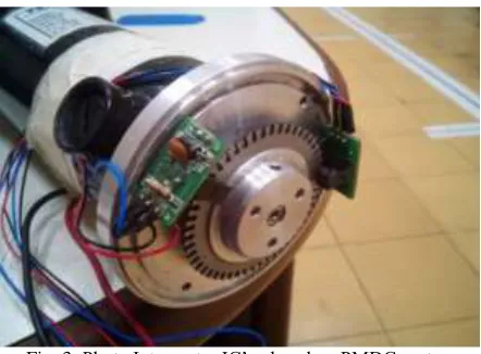
Fig. 3: Photo Interrupter IC’s placed on PMDC motor.
counts, hence we can easily find the number of counts required for 180 degree’s rotation, that will be 3000 counts. Hence for the full day time, the final target will be set as 3000 counts. In this case, target is given as 4 or SPA in our case, since there are two channels CHA and CHB placed 90 degree’s phase shift with each other. The 50 holes made on aluminum plate crosses the two photo interrupter IC’s. The IC detects low pulse as holes and high pulse without holes. The photo interrupter IC produces two pulses when one push is given in PMDC motor. These two pulses when read in decoder it counts four counts information which corresponds to one PWM pulse. The counts may vary according to the designer’s wish. If the target is set for 8 counts, then the PMDC motor rotates once in 2 minutes achieving 0.5 degrees. This technique has been successfully used in sun tracking embedded system.
IV. FLOWCHART AND METHODOLOGY
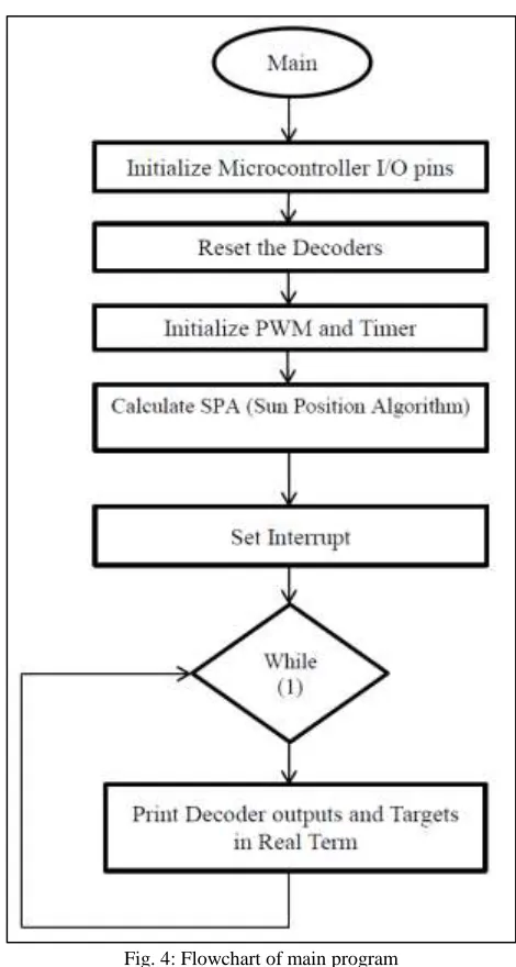
Main Program Flow
Fig. 4: Flowchart of main program
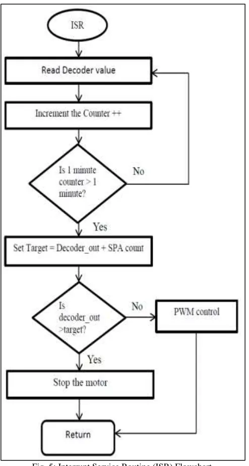
ISR (Interrupt Service Routine) program flow
Fig. 5: Interrupt Service Routine (ISR) Flowchart.
In the main program after the sun position is determined, the sun tracking operation starts. This sun tracking operation is programmed in ISR program. Depending on the frequency of the controller, we get the ISR time. In this case, ISR is called once in 10ms. To get 1 minute, counter variable is used in ISR program. 5999 counts correspond to 60 seconds or 1 minute, i.e., we set counter to count from 0 to 5999 which equals 6000 counts. Once counter crosses 5999 count, Target is set for the PMDC motors. Once the target is set, comparison is done between the decoder counts and target value. When the decoder counts exceed the target value, the motor stops and get activated on next ISR call. If the decoder count is less than the target value, PWM control is given to the motor. The operation of ISR is as shown below.
For DEC_motor target will be set as,
DEC_Motor_Target = DEC_decoder_counts + SPA count. HA_Motor_Target = HA_decoder_counts + SPA count.
V. PCB BOARD DESIGN
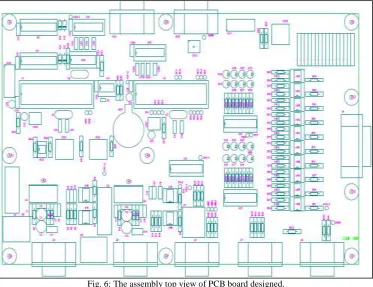
Fig. 6: The assembly top view of PCB board designed.
The RTC is Real Time Clock, which can be used to start the tracking mechanism at a particular time in morning and end up at the particular time set in the evening. The RTC is placed as an optional IC. Since the whole tracking mechanism depends on the encoder and decoder, RTC can be eliminated for the operation. In SPA sub program too, final target can be given. The final decoder count is known, once the final decoder count like 3000 count for a day is set, the tracker continues the operation till 3000 counts, once this count is achieved the parabolic reflector or solar panels is bought back to its original position where the operation was started at the morning. Hence we do not need RTC. The external power is taken via DB9 connectors and DB15 connector is connected to the encoders of PMDC motor.
VI. SOFTWARE AND MECHANICAL STRUCTURE
For the operation of the sun tracking system, Atmel’s AVR studio 4 has been used. The programming language used is Embedded C. To display the results on PC/Laptop, Real Term software is used with 2400 baud rate.
The mechanical structure used for the operation is parabolic sun light reflector. It is named as PSL (Passive Sun Light) collector system in the research laboratory. The mechanical structure is as shown below and its specification is,
Fig. 7: Parabolic Sun Light reflector placed in Research Lab.
Table – 1
Parabolic reflector specification
VII. RESULTS
PCB board was tested manually and then tested on the parabolic mechanical structure present in the research laboratory. First the manual mode program was tested using switches present on PCB board. There are 3 switches, in which one switch is used to start the operation. As second switch is pressed, the North-South (HA_motor) rotates 0.24 degree per switch press and the third switch for East-West (DEC_motor). Next the tracking program is tested. The results of the tracking system are as below.
Fig. 8: DEC_motor result.
As shown in the above result snapshot of Real Term software, the DEC_motor target is set as 12 counts and the DEC_Decoder_count is 8 counts. The motor moves extra 4 counts to achieve 12 counts.
For the testing purpose only the seasonal motor (HA_motor) is used. Target is set as 1 once in predefined ISR call for HA_motor. The result is displayed on Real Term software.
The sun light collected using the parabolic mechanical structure using optical fiber is as displayed below.
Fig. 10: Lights obtained via optical fiber.
The light obtained results is as below,
Table – 2
Results obtained with sun tracker installed on parabolic sun light collector system. Sun Light Obtained Display (Intensity of Light) in Luminance. Full sun light (Sunny day) 500 – 600 Lux.
Partial Sun Light (Cloudy) 200 – 300 Lux
Fig. 11: The sun light via optical fiber.
VIII. APPLICATIONS AND ADVANTAGES
Used as an alternative source of energy in Industries. Can be used domestically for house, office, etc.
Solar tracker is used for both solar panel and parabolic reflector sun light collector.
IX. CONCLUSION
All the testing and work was carried out in Crucible of Research and Innovation (CORI) laboratory, PES University. The PCB board designed has been handed over to the laboratory. The PCB board has the feature of RTC also, so one can make use of RTC and Sun Position Algorithm for continuous operation of sun tracking system even for seasonal movement. Further LDR’s (Light Dependent Resistors) sensors can be used using the same PCB board for the closed loop system to work.
REFERENCES
[2] Michael A. Soderstrand, Synapse International, Sung Baek Lee, Ireh Controls, Peter Chung, Solar Power Energy System, Inc.’s “Mini-Dish Based Hybrid Concentrated Solar Power(CSP) System for Home Use” pp 689-692, 2013, IEEE conference Invited papers.
[3] Salih FADIL, Ahmet Can ÇAPAR, Kerim ÇA_LAR’s “Two Axis Solar Tracker Design and Implementation”, pp 554-557, 2013, IEEE conference. [4] A.H. Yamin, M. N. Ibrahim, M. Idroas and A.R. Zin’s “Embedded Solar Tracking Instrumentation System” pp 223-227, 2013 IEEE 7th International
Power Engineering and Optimization Conference (PEOCO2013), Langkawi, Malaysia. 3-4 June 2013.
[5] Nur Mohammad, Tarequl Karim, “Design and Implementation of Hybrid Automatic Solar Tracking System”, Journal of Solar Energy Engineering 2012 by ASME February 2013, Vol. 135.
[6] Mohammed Mostefa, Ph.D., IEEE, and Abdul Al-Azzawi, Ph.D, Patrick Couture, IEEE, SMIEEE Algonquin College, Ottawa, Ontario, Canada. “Designs of Solar Collector for Hybrid Fiber Optic Lighting System”, 2010 IEEE Electrical Power & Energy Conference.