ISSN (Online): 2320-9364, ISSN (Print): 2320-9356
www.ijres.org Volume 3 Issue 3 ǁ March. 2015 ǁ PP.67-73
The Drill Geometry Influence on PCB Drilling Performance
Huang Lixin, He Xiangsheng
Mechanical Engineering College, Shanghai University of Engineering Science Shanghai, 201620, China
Abstract:
To adapt to the rapid development of PCBs, a high-property drill is desired. An applicable way is demonstrated by a design method based on analysis of drill structure, cutting force experiment , cutter wear observation to improve the drilling performance.Finally the drill wear is well improved by web thinning and chip dividing groove grinding.Keywords
: PCB; Drilling; Thrust force; WearI.
Introduction
As the electronics develops, the PCB is widely used. Very frequently drilling is a preliminary operation to PCB production. The common PCB drilling can be divided into two types: one is the microhole drilling. Microhole is the important part of the PCB. These holes, vias or blind vias, connect an internal copper layer to an outer layer, or opposite sides of the PCB . The microhole drill’s diameter is within 0.03~0.4mm range. The other type is the position hole process. The position hole’s diameter is usually above 2mm. Comparing with microhole, the position hole process is the big diameter process. There are unsmooth chip removal, drill wear, serious burn while using common drill to do the job. With the rotation speed increasing, these problems are much more serious. Although the number of position holes is less than the microholes, the drill consumption is still larger due to the more material removal of bigger hole.
PCB is quite different from common metal. It is multi-layer composite material combined by thin copper foil typically laminated together with epoxy resin prepreg. The PCB drilling process includes the stretching and crushing of plate, the shearing of glass fiber and the cutting and friction of the metal and resin. How to lengthen the drill life needs to consider all about these effects. The numerous researches indicate that the common drill is not fit for the PCB processing. There are many researches on the composite material drilling. Fu and his workers studied the effects of the drill structure and material on the hole quality. The paper shows that the bigger helix angle drill can get better quality while the drill helix angle varies from 25° to 45°. A.M.Abra studied the thrust force varying and post-process layer-split with different drill structure drilling glass fiber-strengthening composite material. The study shows that the grinded drill’s thrust force is smallest and the hole quality is best by comparing 4 types different drill’s thrust force and the hole quality after drilling composite material. And that the hole quality is related to machining conditions directly and the thrust force somewhat. Wang Xin studied the technique of fiber composite material vibrating drilling. The report indicates that the thrust force of vibrating drilling is lower than the common drilling. Meanwhile the thrust force of carbide tools is smaller than the high-speed steel tools’, and more suitable for fiber material processing.
This essay is aiming at studying the large diameter drill for position hole and at getting the appropriate drill geometry through the drill performance experiments.
II.
PCB drill structure’s analysis and improvement
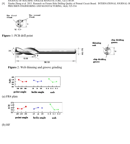
PCB drill structure is different from common twist drill for metal. Thediameter of PCB drill’s stock is all 3.175mm. The current standard PCB drill structure is similar to common twist drill where main parameters are point angle 2Φ, helix angle β, web thickness w. In addition to the different stock sizes, the main difference is that the PCB drill has two flanks, that is the first flank and the second flank, and the larger web thickness, as shown as Figure 1.
rake angle will also increase, but too much large helix angle will weak the drill strength, especially to the cutting edge. The point angle has an effect on the chip direction and cutting force. Different materials should choose appropriate point angles to adapt to the different material processing.
The geometry that an ordinarily provided on a drill represents a compromise of several conflicting requirements, which include the following:
(1). A small web to reduce thrust on the drill but a large web for greater resistance to chipping and greater torsion rigidity.
(2). Small point angle to provide sharper and better centering but larger point angle in the interest of the sooner full cutting action of lips and narrow ribbon.
(3) An increase in the helix angle to more quickly remove chips but a decrease in helix angle in the interest of greater strength of cutting edges.
Basing on the above analysis, the current common PCB drill structure must be redesigned for the cutting performance improvement, as shown in Figure 2. The main actions are following:
(1). Thinning the web of a drill properly.
(2). Adding chip dividing groove for better chip breaking. The detailed` grinding way shown as Figure 2: grinding two chip grooves at the rakes of the helix flutes of the drill, reducing the chip width and helpful to chip transport.
III.
Experiment process
In order to study the effect of different drill geometry on the drill cutting performance, this drilling experiment carry on the three different PCBs with different point angle 2Φ, helix angle β and web thickness w. By comparing the average cutting force and tools wear to analyze the effect of different drill geometry on the cutting force, the suitable parameters are found and used. The cutter wear is measured by the microscope. Standard drills and improved drills are used in the wear experiment and measure the drill flank wear after drilling 1000, 2000 and 3000 holes respectively.
The cutting experiment is carrying on the high speed drill-mill machine, whose highest speed is 80000 r/min. The drilling force is measured by the SDC-C4F strain drilling force dynameter. The cutter for test is the carbide 3.2mm drill.
IV.
Results and discussions
4.1. Analysis of cutting force
In order to verify the drill performance, 10 types of drills are used in this experiment. Among them, 9 pcs drills are designed by orthogonal experimental. The helix angle is 10°,15°,20°respectively, the point angle is 145°, 150°, 155°, common web and thinner web. In addition, to adopt a standard drill with point angle 165°, helix angle of 30°, web thickness of 0.3mm. The workpiece is the double copper layer PCB plates of different materials: FR4 plate, HF plate, PTFE plate. All the thickness is 1.6mm, the copper foil is 35μm. The cutting parameter is: main spindle
rotation speed of 20000 rpm, feed rate of 42 cm/min or 0.021 mm/rev, return rate of 500cm/min.
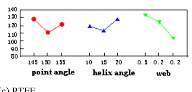
In the Figure 3, the thrust force of 3 types’ plate indicates that the web thickness have largest effect on the thrust force and the lesser one is the point angle and the helix angle is the smallest. Due to the different properties of three materials, the force varying is different while 3 geometry parameters changing. In drilling HF plate, it is biggest at the helix angle of 15°. For the other two plates, thrust force is smallest at the angle of 15°. From the above, the optimizational combination of the parameters is: point angle of 150°, helix angle of 15° and web thickness of 0.2 mm. The web should be grinded properly because the edge thickness affects the force most.
4.2 Drill wear
The Figure 4 is the typical graph of drill flank wear. The drill edge wear is uneven. It’s usually divided into the corner wear area and the main edge wear area. The corner wear area shows the abnormal triangle where the wear is serious due to its lower strength and higher temperature. The maximum width of wear belt is indicated by VC, and also called corner wear. The main edge and web wear area is more even and with smaller width VB and called avenge flank wear. Experiments indicate that no matter the rotation speed is high or low or any time, the width of corner wear band is widest and develops the most quickly. And this graph’s feature is kept unchangeable. The same drill is adopted in the experiment to drill the certain thickness’ PCB plate with different feed rate and study the effect of feed rate on the drill wear. The results are illustrated as Figure 5. With the feed rate increasing, the drill wear aggravate, even the edge collapse occurs.
wear VC are initially small when the tip is sharp, but as drilling continues the wear increased. When the numbers of hole arrived at about 4000, the drill wear intensified greatly. Figure 5 also shows that there is no big wear difference between different point angle drills. At the same time, the drill with web grinded and chip dividing grooves shows better anti-wear performance (shown as Figure 6).
The improved drill from wear test is made which geometry parameters are selected. The improved PCB drill proves better performance by measuring the flank wear. Its life is obviously longer than the standard drill from the wear test results in Figure 6. The improved drill’s wear is only half of the standard one after drilling 3000 holes. The improved drill’s flank and corner wear is obviously less the standard one by the figure. It is because the drill’s outer corner is grinded to reduce the friction between drill outer margin with the hole wall. In this way, the friction’s heat is reduced and improve the hole wall quality. The cutting heat is difficult to release for the drilling in the semi-hermetic processing. The chips in drilling PCB is mostly the continuous floccule which is different from the fragmented chip in drilling cast iron. Its main component is resin and combined with the breaking glass fiber. This type chip is easy to melt and stick to the cutter and block the flutes which lead the poor chip removing and high cutting temperature, so the cutter wear is intensified. The chip dividing groove’s effect is mainly the chip breaking and transporting. Grinding two V type grooves on the main cutting edge, the whole edge is broken into 4 shorter edges. The chips width reduces so that the chip is easy to break and the main edge loading is lower and chip is easy to bring out.
4.3 Selection of cutting conditions
Due to the different properties for each type of drilling machine, for different materials , its drilling parameters are also different. The better property spindle, its spindle speed is high, the feed rate and rising speed is faster equally.So, screening our experienced parameters by experiment, then obtain the best parameter combinaton under the certain type drill machine and the certain diameter drill. Figure 7 is the effect of the feed rate and cutting speed on thrust force.
The feed is the cutting rate per rotation. The commonly allowed maximum value is about 13% of drill diameter, get 5%-7% of drill diameter, 10%-12% at high speed drilling. The f value is from 0.02 mm/r to 0.2 mm/r. When f<0.02mm/r, cutting edge feed is so little that cause much friction heat at scraping and intensify the wear. When f>0.2mm/r, the cutter edge breaking may occur at the start of cutting. At this time, the cutting edges are seriously damaged and failed with the poor hole quality and the low effectiveness.
Based on the experiment result, the proper feed is 0.005—0.15mm/rev, that is, 100-300cm/min, and the optimum is around 0.1mm/rev (200cm/min) for 3.2mm PCB drill. The wear volume is seen to increase with feed. Thus, from the point of view of wear volume, a small feed is advantageous. However, if feed is too small, the wear will increase seriously instead. This conclusion conforms to the cutting theory.
It’s observed that while f<0.02mm/rev the chip deformation is big and the cutting is not light. The cutting is like scraping and the aluminum chip is like conical helical which take more space and probably to block and difficult to break which affect the drill cooling effect and cause serious wear. The aluminum chip is long continuous ribbon and wind on the drill as Figure 9 illustrated. This kind chip is not easy to break. While the feed rate is 0.1mm/rev (200cm/min), the chip is discontinuous and cutting light. The aluminum is short fragment and easy to break and exit.
When the feed amount is 0.1mm/r(200cm/min), the copper chips is chopped shape, cutting smoothly, naturally curly and disconnect. The cutting chips is easy to remove and clean. The ideal copper chips shape should be C-shape or helical shape with length 30mm approximately.( shown as Figure 10 ) .
Figure11 is the wear morphology photos in the wear process, the cutter wear mainly concentrate in the flank face and cutter tip. When the feed speed is 0.0013mm/r, the flank face will form long and wide wear belt, it indicates cutter wear severe, that because drill works in the hardening layer, accelerating cutter wear, meanwhile the cutting chips is ribbon shape and unfavorable for cutter wear. While feed rate 0.1 mm/r, the drill wear vestige is not obvious after drilling 500 holes, even after drilling 2000 holes the cutting edge wear is still not large. While the feed rate is increasing to 0.175 mm/r and 0.2 mm/r, edge breakage occurs. The cutter fails and edge breaks serious after drilling 500 holes.
V.
Conclusions
(1) PCB drilling has many problems, such as difficult chip breaking and removing and fast wear etc. The experiments verify that the improved geometry PCB drill has better performance.
(2) The cutting experiments verify that the effect of web thickness to the drill performance is biggest, the next is the point angle and the last is the helix angle. So thinning web to reduce the cutting force is necessary. (3) Based on the wear experiment, it concludes that the drill wearing capacity is well improved by thinning web
Acknowledgements
Project supported by the Key Program of NSFC-Guangdong Joint Fund, China(Grant No. U0734007 ), and by Shanghai Baoshan Science & Technology Innovation Fund (CXY-2012-18).
References
[1] Printed circuit board - Wikipedia, the free encyclopedia, http://en.wikipedia.org/wiki/Printed_circuit_board#Drilling
[2] Fu Lianyu etc. 2008. A solution for PCB drilling with strict requirement on hole wall quality. Circuit world, 34, 8-11
[3] A.M. Abrao etc. 2008. The effect of cutting tool geometry on thrust force and delamination when drilling glass fiber reinforced plastic
composite. Material & Design, 2008 (59):508-513
[4] Wang Xin etc. 2004. Investigation on thrust in vibration drilling of fiber-reinforced plastics. Materials Processing Technology, 148,
239-244
[5] W. H. Kao. 2009. Tribological properties and high-speed drilling performance of Zr–C:H:Nx% coatings with different amounts of
nitrogen addition. J Mater Sci (2009) 44:3488–3497 . DOI 10.1007/s10853-009-3467
[6] P.J. Arrazola, D. Ugarte, X. Domınguez. 2008. A new approach for the friction identification during machining through the use of finite
element modeling. International Journal of Machine Tools & Manufacture, 48 (2008) 173–183
[7] Milton C. Shaw. 1984. Metal Cutting. Clarendon Presss. Oxford, 1984,463
[8] Zheng, Lijuan et al. 2012.Characteristics of chip formation in the micro-drilling of multi-material sheets. INTERNATIONAL
JOURNAL OF MACHINE TOOLS & MANUFACTURE, 52(1): 40-49.
[9] Xiaohu Zheng et al. 2013. Research on Fixture Hole Drilling Quality of Printed Circuit Board. INTERNATIONAL JOURNAL OF
PRECISION ENGINEERING AND MANUFACTURING, 14(4): 525-534
Figure 1: PCB drill point
Figure 2: Web thinning and groove grinding
(a) FR4 plate
(c) PTFE
Figure 3: Effect of the drill geometry on thrust force (Drilling condition: 3.2 mm, 20000 rpm, 0.021 mm/rev)
Figure 4: typical graph of flank wear
0 0.01 0.02 0.03 0.04 0.05 0.06 0.07 0.08 0.09
200 500 1000 1500 2000 2500 3000 3500 4000 4500 Nunber of holes
T oo l w ea r ( V B ) 145° 125° 105° 0 0.05 0.1 0.15 0.2 0.25
1000 1500 2000 2500 3000 3500 4000 4500 Number of holes
T ool w ea r ( V C ) 145° 125° 105°
Figure 5: Drill wear vs time
(Drilling condition: FR-4,3.2 mm, 30000 rpm, 0.05 mm/rev)
Figure 6: Drill wears for different geometry
(Drilling condition: FR 4, 3.2 mm, 20000 rpm, 0.021 mm/rev)
0 10 20 30 40 50 60 70 80
100 300 500
f(cm/min)
s:20000rpm s:40000rpm s:60000rpm
(a)Average wear width (b)Corner wear
Figure 8: Feed vs drill wear
(Drilling condition: FR 4, 3.2 mm, 20000 rpm)
0.013 mm/rev 0.025 mm/rev 0.05 mm/rev 0.075 mm/rev
0.1 mm/rev 0.125 mm/rev 0.15 mm/rev 0.2 mm/rev
Figure 9: Aluminum chips for different feeds (Drilling condition: FR 4, 3.2 mm, 20000 rpm)
0.013 mm/rev 0.025 mm/rev 0.05 mm/rev 0.075 mm/rev
0.1 mm/rev 0.125 mm/rev 0.15 mm/rev 0.2 mm/rev
(Drilling condition: FR 4, 3.2 mm, 20000 rpm)