Customized Progressive Lens Based On Head
Frequency Movement From The Frequency Map
MaramReddy Divya, V. Punna Rao
M.Tech (Computer Science) Vasavi College Of Engineering, Osmania University, Hyderabad.
Assistant Professor, Department Of Computer Science, Vasavi College Of Engineering, Osmania University, Hyderabad Maramreddydivya@gmail.com, Punnarao.vuyyuru@gmail.com
ABSTRACT: The proposed system is for designing progressive lenses. This method permits generation of lens design based on the head and eye movements of an individual. For this a camera is used for imaging the head and eye of a person. It relies on tracking algorithms to robustly track a person’s head and eye movements. This system classifies rotation in all viewing directions, and detects head movements. Based on this information head frequency map is generated. Once the eye and head frequency map is generated they are combined to form a generalized frequency map. This map is then used to suggest the patient with the customized progressive lens.
Index Terms: Cascade Classifiers, Customized Progressive Lens, Head Movements, Head Tracking, Lens Design, Vision comfort.
1.
Introduction
Losing the normal vision is the common problem facing by human beings in the present world. These problems occur when the image is not properly focused on retina. These prob-lems are usually corrected by using spectacles or contact lens. To test the eye sight of the patient in the present system, we have manual testing and computerized or Tablet based eye testing. By using any of these techniques eye sight of the pa-tient is determined. This type of traditional method users are just choosing the spectacles that is of stylish and suits them, even if wearing of such spectacles is of no use to them. So once as it is found that if the patient is having the eye sight or not, even if there is no eye sight and patient is interested to wear the spectacles to protect his eyes while reading or watch-ing the screen then there should be an approach uswatch-ing which we can suggest the person with customized progressive lens by monitoring their observations whether a person is moving his/her head or eyes to see any object or screen.
Drawback of Conventional Method to design lens
There are many conventional methods for designing Spec-tacles lens in which they develop theoretical Target values by obtaining Subjective Patient feedback using objective testing methods to design lens.
They do not correlate patient feedback and objective testing to precise locations on lens.
Thus the point at which an individual’s line-of-sight ac-tually intersects with the len’s surface differs from the calculated by the len’s designer.
Therefore, a method for designing lenses that over-comes these disadvantages is needed.
1.1 Overview
The main objective of this project is to design algorithm for head movements tracking. Array of LED’s arranged in the semi-circle pattern on the screen. Same pattern on the upper screen and also on the lower screen with that it completes the circle. We capture the video of that person while observing the LED lights that are mounted on the screen and they are de-signed to glow in some specific pattern. The motion of the pa-tient’s head and eye while observing the LED pattern is conti-nuously monitored by camera and information is stored and processed. By giving this video as the input to our proposed system we are tracking the head movements of the person
and plotting the head frequency graph according to head movements in that video. Based on this frequency map we suggest customized progressive lens in order to provide visual comfort to the lens wearer.
1.2 Motivation
The motivation behind this project is to develop an application that can be used for vision analysis to suggest patient with customized progressive lens in order to provide vision comfort to the lens wearer.
1.3 Problem statement
Head movements of a person are tracked while the person is watching the glowing LED pattern to generate the head movement’s region map. Then we can suggest the Custo-mized progressive lens based on the shape of the head movements region map that has been generated.
1.4 Objective
The main objective of this project is to recommend customized progressive lens which are useful to the user while choosing lens and minimize user’s effort to choose the suitable glasses and provide the visual comfort to lens wearer.
1.5 Modules
This project is divided into two modules.
1. Method for designing spectacle lenses taking into account an individual’s head movements. 2. Method for designing spectacle lenses taking into
account an individual’s eye movements.
This paper mainly deals with the Head movements Tracking and Generation of Head Movement Region Map.
1.6 Required Specifications
1.6.1 Hardware Requirements are: LED’s
Camera
Sensor
Trial Frame
1.6.2 Software Requirement are:
Operating System : Windows
Simulation Tools : OpenCV
Coding Language : Java
IDE : NetBeans 8.0
2. Proposed System Design
The main objective of a head tracking system is to track the head movements of an individual. So we need to track the Head movements of an individual in a video. . For this a cam-era is used for imaging the head and eye of a person. It relies on tracking algorithms to robustly track a person’s head and eye movements. This system classifies rotation in all viewing directions, and detects head movements. Based on this infor-mation head frequency map is generated. Once the eye and head frequency map is generated they are combined to form a generalized frequency map. This map is then used to suggest the patient with the customized progressive lens in order to provide visual comfort to the lens wearer.This paper presents some background knowledge required for the creation of a head tracking system and will describe some tracking tech-niques used within the proposed system.
2.1. Head and Eye Tracking Device
Array of LED’s arranged in the semi circle pattern shown in the diagram below. Same pattern on the upper screen and also on the lower screen with that it completes the circle. Two sensors are arranged on both sides of the upper screen, they sense the motion of the head trail frame which has four led’s. Head and eye movements of a person are tracked while he/she is observing the light glowing along the LED’s line.
FIGURE 1: Screen Design Pattern
FIGURE 2: Upper Screen
FIGURE 3: Lower Screen
FIGURE 4: Bottom Screen
Initially after setting up the device we make the patient to sit infront of the device with a distance of 510mm away from the device. We capture a video of that person while observing the LED lights that are mounted on the screen and they are de-signed to glow in some specific pattern. The motion of the pa-tient’s head and eye while observing the LED pattern is conti-nuously monitored by camera and information is stored and processed. By giving this video as the input to our proposed system we are tracking the head movements of the person and plotting the head frequency graph according to head movements in that video. After generating the head frequency map we combine the eye frequency map to get a generalized frequency map. Based on this graph we can suggest the pa-tient with suitable customized glasses.
3. Experimental Results
By making use of card board and chart we have made a sample Head and Eye tracking device. We have fixed a pat-tern in which LED’s has to glow with minimum number of repe-titions. We made a person to sit infront of this device with a minimum distance apart of 50mm from the device. After mak-ing the person sit comfortably we asked him to watch the screen while the Laser Light is being passed through the screen holes in a specified fixed pattern. Then by making use of an HD camera we have captured different videos multiple persons while watching the set up screen to find whether the person is moving his head or eyes to follow the light pattern.
47 cm
FIGURE 5 : LED’s Design Pattern
FIGURE 6: Sample Model of Head and Eye Tracking Device
4. Proposed Algorithm Steps
Steps followed to achieve the required results are:
1. Make the patient to sit in front of head and eye movement device and ask patient to watch the screen.
2. Start the device where the LED lights glow in some specific pattern. Store the point at which LED is glow-ing and its correspondglow-ing time in an excel file known as static excel file.
3. Start capturing the video when the patient is watching the glowing LED’s during the experiment.
4. By giving the captured video as the input to our sys-tem we identify the head movements in that video. 5. Track the head movements from that video by using
Haar-classifier from openCV library.
6. Compute the frame difference using kalman filter al-gorithm by considering first frame in the video as the reference frame/image with sequence of frames in the video.
7. Store the frame difference separately for head move-ments and eye movemove-ments.
8. Where ever there is a frame difference found for head movements then it means that head is used to look at LED.
9. If there exists any movement related to head we store the co-ordinate points (x, y) of previous frame and the current frame. By making use of distance formulae identify the exact movement in pixels and also the angle by using tan function in which direction head is moved.
10. Based on the movement field where the movement is greater than or equal to threshold we plot the co-ordinate points as a graph.
11. Based on the frequency and time factors we distin-guish the map with three different colors.
12. This map is referred as head movement region map. 13. The same procedure is followed to generate Eye
movement frequency map.
14. Combine both head and eye movement maps to get a generalized map referred as head and eye move-ment’s region map.
15. If the shape of the map is horizontal we suggest pa-tient with wider glasses horizontally if map looks verti-cally we sucggest with more width vertiverti-cally.
16. Based on the shape of this map suggest the patient with customized progressive lens to provide visual comfort.
4.1 LED Position and Direction of Glowing pattern
LED’s arrangement pattern is drawn on the Graph sheet and we have fixed the pattern in which the LED should glow based on minimum repetition of the line segments. The gap between each LED is specified as 2mm. After ar-ranging all the LED’s on to a graph we noted the co-ordinate points of each and every LED glowing in a static Excel sheet.
4.2 Video Capturing
We made different persons to sit comfortably on chair infront of this setup (i.e Head and Eye Tracking Device) at a distance of 50mm and asked the person to watch the screen while the Laser Light is being passed through the screen holes in a specified fixed pattern. Then we have captured the videos of multiple persons while watching the set up screen to find that whether the person is moving his head/eye to follow the light pattern.
FIGURE 8 : Videos Captured During Experiment
4.3 Tracking Head Movements In a Video
To track head movements in a video initially we need to identi-fy the face from the video for this we made use of Haar-Classifier class from openCV library then Kalman Filter algo-rithm is used to identify the movements in the video.
Haar Classifier
The proposed algorithm depends heavily on the open-source library OpenCV. Object Detection using Haar feature-based cascade classifiers is an effective object detection method proposed by Paul Viola and Michael Jones in their paper, “Rapid Object Detection using a Boosted Cascade of Simple Features”. It is a machine learning based approach where a cascade function is trained from a lot of positive and negative images. It is then used to detect objects in other images.
Internal working of Haar-Classifier
• Initially, the algorithm needs a lot of positive images (images of faces) and negative images (images with-out faces) to train the classifier.
• Then we need to extract features from it such as nose, eyes, mouth…etc
• If an image is given as the input to the classifier it compares with the positive images and if a match founds then it returns the face from the given image.
• In our proposed system Cascade Classifier class is used to detect objects in a video stream.
4.4 Head movements graph generation
From the input video identify the face part by using cascade and mark it using a rectangle bounding box to highlight only
the face part from the video. According to our head move-ments the line graph is plotted as below.
FIGURE 9 : Head movements Trace Graph generation
5. Frame Difference
By giving the video as an input to our method we are going to track the head movements using kalman filter algorithm in that video.
5.1 Kalman Filter
This describes a method for the computation of the optical flow in a sequence of images acquired by a moving camera. This is an optical flow estimator.The motion is estimated using a line-based scanning of the image.In order to use this model, three main hypotheses must be satisfied:
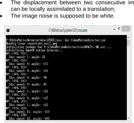
The illumination is supposed to be constant between two consecutive images of the sequence;
The displacement between two consecutive images can be locally assimilated to a translation;
The image noise is supposed to be white.
FIGURE 10 : Distance and Angle.
By using kalman filter algorithm we obtained the frame differ-ence in pixels for each and every frame in a video. After get-ting all the values we are storing these values in an excel sheet.
5.2 Fields in the Excel Sheet
Frame ID: This is the first field in our Excel sheet. Video is nothing but sequence of frames. For each and every frame in a video we are going to give numbering in sequence manner. This field is added to identify at which frame there is a move-ment.
this we are initially fixing the position of the cross symbol at one place. This point is stored and from this point the ment is traced the cross moves according to the head move-ments based on the cross position we are noting the X and Y values for the next frame.
Movement: This field consists of only two values such as 0 and 1. By finding the frame difference between the frames we are going to decide the value as 0 or 1. If there exists frame difference between two frames we conclude that there is a movement from previous frame to next frame we store the value as 1 at this frame ID. If there is no movement we just simple give a value as 0 at corresponding frame.
Distance Calculation: In this we are going to calculate the distance between two points by making use of the basic dis-tance formulae as follows:
Ex: int xStep = cogPoint.x - prevCogPoint.x;
int yStep = -1 * (cogPoint.y - prevCogPoint.y); int distMoved = (int) Math.round(Math.sqrt((xStep *
xStep) + (yStep * yStep)));
Angle calculation: To identify in which direction face has been moved we need to calculate the angle. To calculate the angle we need three points here we are considering initial fixed point, previous point and current point based on this we are going to get a triangle by making use of tan function we can determine the angle in which the head moved.
Syntax: int angle = (int) Math.round(Math.toDegrees( Math .a tan2(y, x)));
Direction:
If the angle is between -23& 23 we give direction as 1.
If the angle is between 23& 68 we give direction as 2.
If the angle is between 68& 113 we give direction as 3.
If the angle is between 113& 158 we give direction as 4.
If the angle is between 158& 180 or -157 we give di-rection as 5.
If the angle is between -157& -112 we give direction as 6.
If the angle is between -112& -67 we give direction as 7.
If the angle is between -67& -22 we give direction as 8
If the angle is 0 we give 0 in direction field also.
Frequency: This field is calculated based on movement field if the value in movement field is 1 then the same will be re-flected in frequency field too. if the value in movement field is 0 then the value in frequency field depends upon the count of 0’s. if we have single zero we place 1 in the frequency field, if
we have of sequence of 0’s consequently then the count of that 0’s is placed in the frequency field at the respective frame. This field shows how frequently we are looking at one position. This field is mainly used to plot the graph.
Elapsed Time: This field is calculated based on the video playing time w.r.t system time. Initially at previous frame we consider the system time and store and then the system time at current frame.by subtracting time at previous frame and current frame we are going to get the elapsed time between those frames.
Ex:
movedTimeP=System.currentTimeMillis();
movedTimeC=System.currentTimeMillis();
eTime=movedTimeC-movedTimeP;
movedTimeP=movedTimeC;
CSV: A comma separated values (CSV) file contains different values separated by a delimiter, which acts as a database ta-ble or an intermediate form of a database tata-ble. By making use of CSV we save all the values to an Excel sheet as fol-lows:
FIGURE 11 : Data In Excel Sheet
By making use of JFree Charts we finally plot the graph. The graph looks like this when no colour is given. Here all points are just plotted where there is a movement with single colour.
5.2. Color Graph
Based on the the frequency or time factors we can differentiate the graph with three different colors as follows:
Colour1 represents maximum density,
Colour 2 represents medium density and
Colour 3 represents lower density.
FIGURE 13 : Head Movements Region Map
Once after getting the head frequency map we combine with eye frequency map to generate a generalized frequency map.If the graph looks like an horizontal graph we suggest the patient with more horizontal shaped glasses if it is more vertic-al we suggest vertiacvertic-ally wide glasses.
6. Conclusion
The main objective of this project is to generate the Head Movement Region Map based on the head movements made by the person while observing the glowing LED pattern. This map information is then used to suggest the person with the customized progressive lens and provide vision comfort to the lens wearer.
Future Work
This Experimental idea or proposed system can be imple-mented in the design of real time Eye and Head Movement Tracking Device which can be used in the Eye sight testing centers to prescribe the patient with the appropriate design of the lens which best fits the patient according to his/her head and eye movements made to look at particular object.
References
[1] J. Ahlberg and R. Forchheimer. Face tracking for model-based coding and face animation. International journal of imaging systems and technology, 2003.
[2] A. Azerbayejani and A. Pentland. Recursive estima-tion of moestima-tion, structure, and focal length. IEEE PAMI, 1995.
[3] S. Basu, I. Essa, and A. Pentland, ªMotion Regulari-zation for Model- Based Head Tracking,º Proc. Int'l Conf. Pattern Recognition, 1996.
[4] S. Birchfield, ªAn Elliptical Head Tracker,º Proc. 31st Asilomar Conf. Signals, Systems, and Computers,
[5] M.J. Black and A. Jepson, ªEigentracking: Robust Matching and Tracking of Articulated Objects Using a View-Based Representa- tion,º Int'l J. Computer Vi-sion, vol. 26, no. 1, pp. 63-84, 1998.
[6] M.J. Black and Y. Yacoob, ªTracking and recognizing rigid and Nonrigid Facial Motions Using Local Para-metric Models of Image Motions,º Proc. Fifth Int'l Conf. Computer Vision, 1995.
[7] M.J. Black and Y. Yacoob, ªRecognizing Facial Ex-pressions in Image Sequences Using Local Parame-terized Models of Image Motion,º Int'l J. Computer Vi-sion, vol. 25, no. 1, pp. 23-48, 1997.
[8] T.F. Cootes, G.J. Edwards, and C.J. Taylor, ªActive Appearance Models,º Proc. Fifth European Conf. Computer Vision, 1998.
[9] J.L. Crowley and F. Berard, ªMulti-Modal Tracking of Faces for Video Communications,º Proc. Conf. Com-puter Vision and Pattern Recognition, 1997.
[10]D. DeCarlo and D. Metaxas, ªThe Integration of Opti-cal Flow and Deformable Models with Applications to Human Face Shape and Motion Estimation,º Proc. Conf. Computer Vision and Pattern Recognition, 1996.
[11]Santa Birchfield. Elliptical head tracking using intensi-ty gradients and color histograms. In Proc. of Interna-tional Conference on Computer Vision and Pattern Recognition, pages 232– 237, 1998.
[12]Thierry Chateau, Vincent Gay-Belille, Frederic Chausse, and Jean-Thierry Lapreste. Realtime track-ing with classifiers. In Proc. of International Workshop on Dynamical Vision in conjunction with ECCV, 2006.
[13]Michael Isard and Andrew Blake. Condensation - conditional density propagation for visual tracking. In-ternational Journal of Computer Vision, 29(1):5–28, 1998.
[14]Ronald Azuma and Mark Ward. 1991. “Space-Resection by Collinearity: Mathematics Behind the Optical Ceiling Head-Tracker,” UNC Chapel Hill De-partment of Computer Science technical report TR 91-048 (November 1991).