Energy Efficient Variable Speed High Power
Factor Three Phase Induction Motor Drive using
Combined PWM and Extinction Angle Control
Mrs. S.H. Deshmukh Ms. Medha R. Giri
Student Student
Department of Electrical Engineering Department of Electrical Engineering
SRCoEM SRCoEM
Afsana Shaik Dr. D.R. Tutakne
Student Professor
Department of Electrical Engineering Department of Electrical Engineering
SRCoEM SRCoEM
Abstract
Paper presents a new energy efficient technique of three phase AC to AC voltage control using medium frequency pulse width modulation and extinction angle control. This technique is deployed to obtain independent control on speed and power factor of the three phase induction motor, using four semiconductor controllable switches. The technique has been realized using AC freewheeling switch. Power factor (PF) of induction motor reduces as it depends on the load parameters, thus induction motor draws more current, increase stator copper losses. Increased stator copper losses of induction motor causes depreciation of power factor and efficiency. Proposed drive maintains power factor of induction motor at unity for controllable speed of the motor. Thus reduces current consumption of the motor at low speeds. Stator copper losses also reduce and efficiency of the motor is improved. Advantage of proposed drive is its higher efficiency and unity power factor with simplicity of control. .If number of motors are driven using the proposed drive, plenty of power conservation is possible.
Keywords: Extinction Angle Control (EAC), Pulse Width Modulation Control (PWM), Extinction Angle (β), Power Factor (PF), Induction Motor (IM)
_______________________________________________________________________________________________________
I. INTRODUCTION
Energy saving is energy generation. Now-a-days power conservation is an issue across the globe.Three phase induction motor is most widely used in industries than other machines due to their advantages such as simplicity in construction, reliability in operation, and cheapness. The speed control of such motors can be achieved by controlling the applied voltage on the motor by the use of power electronic devices [1]. AC voltage controllers as power converters are also used as induction motor soft starter .But this suffers from several disadvantages such as retardation of firing angle, poor input power factor, complex control techniques and large number of switches [2]. Three phase induction motors (IM) for fans and blowers applications in industries are mostly driven through variable voltage variable frequency (VVVF) drive that provides speed control of induction motor. With VVVF drive, power factor (PF) of induction motor reduces as it depends on the load parameters thus induction motor draws more current, increase stator copper losses. The proposed drive can operate induction motor with unity PF for any speed. Thus improves PF of an industry, using this drive. In addition, it offers free wheeling in AC load. Even for the operation where VVVF is not required with IM this drive can be installed to improve the overall PF of an industry.
II. CONTROL TECHNIQUE
Combined Extinction Angle and PWM Control
losses are reduced efficiency of motor is improved. In this technique only four semiconductor switches are used instead of six as in phase angle control. So, complexity of circuit is also reduced.
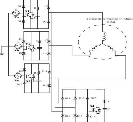
III. POWER CIRCUIT
The power circuit of the proposed technique is shown in Fig.1. In this diagram 3-phase supply is connected to stator winding of 3-phase induction motor through single phase diode bridge along with semiconductor switch(IGBT,GTO etc.) in each phase, whereas instead of three more switches for providing freewheeling path to each phase current only one switch with three phase diode bridge is used. This switch is connected in parallel to the 3-phase stator winding of induction motor.
Hence only four switches are used instead of six. Snubber (R-C) circuit across each of the four switch are connected to provide dead time in between the operation of the main and freewheeling switches.
AC D1 D3 D4 D10 D11 D16 Va AC D5 D6 D7 D8 Vb AC D9 D12 Vc D13
3 phase stator winding of induction motor S2 D2 S1 S3 D15 D17 D18 D14 S4 R C R R C C C R
Fig. 1: Power circuit of combined extinction angle and PWM controlled three phase induction motor drive
IV. MODES OF OPERATION
The operating modes of proposed drive are divided into four modes
Active mode
Dead time-I mode
Freewheeling mode
Dead time-II mode
Active Mode (Mode-I)
AC D1 D3 D4 D10 D11 D16 Va AC D5 D6 D7 D8 Vb AC D9 D12 Vc D13
3 phase stator winding of induction motor S2 D2 S1 S3 D15 D17 D18 D14 S4 R R R R C C C C
The active mode corresponds to the ON-state period of the main switches S1 S2 S3 and during this mode of operation switch S4 remains OFF. When switches S1 S2 S3 are made ON, the current flows from the three phase supply to the three phase stator winding through the switches S1 S2 S3 simultaneously along with forward biased diagonally opposite diodes of the bridge as shown in Fig.2. The supply voltage appears across the terminals of star connected stator winding during mode-I.
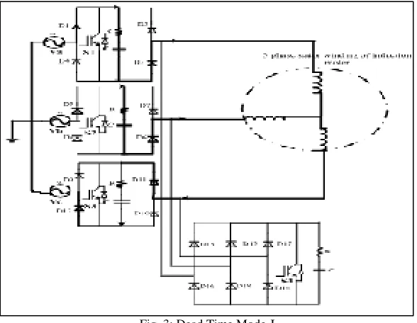
Dead Time-I Mode (Mode-II)
When switch S1 S2 S3 are turned OFF, the stator terminals gets isolated from the AC supply .The stator current flows through parallel snubber circuit (R-C circuit) connected across each switch (S1 S2 S3) for very short time. This short time when three main switches S1 ,S2, S3 are turned OFF and auxiliary switch S4 is about to turn ON is known as dead time-I (mode-II) as shown in Fig.3.
Fig. 3: Dead Time Mode-I
Freewheeling Mode (Mode-III)
The freewheeling auxiliary switch S4 is turned ON during mode-III. In this mode the three phase stator currents will decay and circulates through three phase diode bridge rectifier. The parallel connected freewheeling switch S4 as shown in Fig.4.In this mode, three phase load current discharges its stored energy.
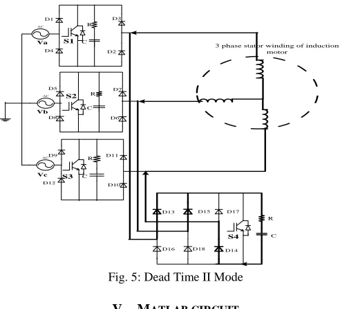
Dead Time-II Mode (Mode-VI)
At the end of mode-III, switch S4 gets turned OFF and main switches S1 S2 S3 are about to turn ON. This short time interval when all the switches are OFF is called Dead time-II (mode-IV) as shown in Fig.5. The input line current during mode-II and mode-IV will be zero, but motor current continues to flow during all the four modes and hence circulates continuously during all the modes. In this mode, snubber across switch S4 completes the path for the current and dead time is provided before switching on the main switches.
AC
D1 D3
D4
D10 D11
D16
Va
AC
D5
D6 D7
D8
Vb AC
D9
D12
Vc
D13
3 phase stator winding of induction motor
S2
D2
S1
S3
D15 D17
D18 D14
S4 C
C C C
R
R
R
R
Fig. 5: Dead Time II Mode
V. MATLAB CIRCUIT
This section presents the performance evaluation of the proposed scheme with the high frequency PWM technique by simulation using MATLAB Simulink. The complete simulation model for soft starting and speed control of 3 phase induction motor using IGBT is shown in Fig.6.
Fig. 6: MATLAB circuit of proposed drive
Table - 1 Simulation Parameter
Sr. No Parameter Value
1 Maximum Supply Voltage 400V 2 Supply Frequency 50Hz 3 Switching Frequency 3kHz
4 Duty Cycle 0.4
5 Load Resistance 50Ω
6 Load Inductance 10mH
different extinction angle (10 degree and 25 degree). Table.1. represents the values of parameters used for simulation and following results are obtained.
VI. SIMULATION RESULTS
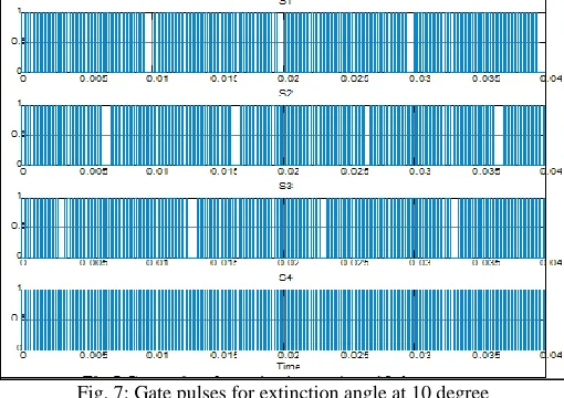
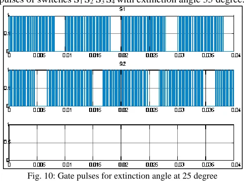
The simulation result in fig.7. are the gate pulses for all the switches (S1 S2 S3 S4) at extinction angle 10 degree obtained by comparing triangular wave of 3khz with dc value of 0.4. PWM pulses obtained for switches S2 and S3 are phase shifted by the pulses of switch S1 by 120 degree and 240 degree respectively. Switch S4 operates in complementary to all the three switches, so the pulses obtained for it are complementary to the pulses obtained for the three main switches.
Fig. 7: Gate pulses for extinction angle at 10 degree
Result obtained in fig.8.are the waveform for the three phase load voltage with an extinction angle 10 degree and PWM of 3khz frequency.
Fig. 8: Load voltage waveform for three phases at extinction angle 10 degree
The result obtained in fig.9. shows the waveform of instantaneous load current for phase A, from which fundamental value of load current can be derived and it can be seen that current is leading supply voltage of phase A by a minimum value of phase angle. Thus the obtained power factor will be near to unity.
Results in the Fig.10 Show the pulses of switches S1 S2 S3 S4 with extinction angle 35 degree.
Fig. 10: Gate pulses for extinction angle at 25 degree
Results obtained in fig.11.are the waveform for the three phase load voltage with an extinction angle 25 degree and PWM of 3KHz frequency.
Fig. 11: Load voltage waveform for three phases at extinction angle 25 degree
The result obtained in fig.12. shows the waveform of instantaneous load current for phase A, from which fundamental value of load current can be derived and it can be seen that current is leading supply voltage of phase A by a some value of phase angle. Thus the obtained power factor will be leading.
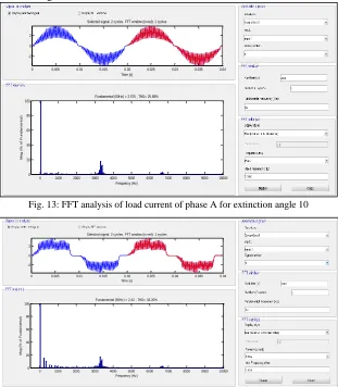
VII.FFT ANALYSIS OF LOAD CURRENT OF PHASE A FOR EXTINCTION ANGLE 10 DEGREE
Figure 13 shows FFT analysis of load current of phase A for extinction angle of 10 10 degree and figure 14 shows the FFT analysis of load current of phase A for for extinction angle of 25 degree. It has been observed that THD for 10 degree is 25.8% and THD for 25 degree extinction angle is 33.3%.
Fig. 13: FFT analysis of load current of phase A for extinction angle 10
Fig.14 FFT analysis of load current of phase A for extinction angle for 25
VIII. CONCLUSION
In the proposed drive desired range of voltage and highpower factor control are obtainable by controlling the extinction angle and PWM control simultaneously. Best results are obtained for extinction angle for 10 degree. In the proposed scheme induction motor is expected to draw comparatively lesser current than VVVF and conventional phase angle controlled drive. The stator copper losses are expected to reduce due to increase in power factor and reduction in magnitude of stator current.
REFERENCES
[1] Nabil A. Ahmed and Emad H. El-Zohri, “Power Factor Improvement Of Single Phase Ac Voltage Controller Employing Extinction Angle Control Technique,” IEEE transaction on Circuits and Systems, vol.3, pp.1075-1080, Dec. 2003.
[2] Nabil A. Ahmed, Masafumi Miyatake, Hyun Woo Lee and Mutsuo Nakaoka “ A Novel Circuit Topology of Three-Phase Direct AC-AC PWM Voltage
Regulator” IEEE transaction on Industry Applications Conference, vol.4, pp.2076-2081, Oct. 2006.
[3] Bilal Saraçoğlu “Supply power factor and load current harmonic performance improvement of three phase AC voltage Controller,” Scientific Research and Essays, Vol. 5 (9), 4 May, 2010
[4] Ju-Sung Kang, Nabil A. Ahmed, Kwang-Joo Choi, Hyun Woo Lee and Mutsuo Nakaoka, “Pulse Modulated AC Voltage Regulator Using Bidirectional Active Switches with Different Control Strategies, ” IEEE transaction Electrical Machines and Systems (ICEMS) , vol.2, pp.1107-1111, Sept. 2005 [5] A.M. Eltamaly ,A.I. Alolah and R.M. Hamouda “ Performance Evaluation of Three-Phase Induction Motor under Different AC Voltage Control Strategies
Part I,” IEEE transaction on Electrical Machines and Power Electronics, pp.770-774, Sept. 2007
[6] Dong-Choon Lee, Member, IEEE, and Young-Sin Kim, “Control of Single Phase-to-Three-Phase AC/DC/AC PWM Converters for Induction Motor Drives,” IEEE transactions on industrial electronics, vol. 54, no. 2, april 2007.
[7] Upama Bose, K. Divya, Vallathur Jyothi, and Sreejith., “ Performance Analysis of Four-switch Three-phase Inverter-fed Induction Motor drive,” IEEE transaction on Power and Energy Systems Conference: Towards Sustainable Energy, pp.1-6, March 2014.
[8] Kushal Dhawad, R.D. Patane and Vittesh Naphade, “Efficient Speed Control of 3-ph Induction Motor with Two Stage IPFC Using 1-ph Supply,” International Journal of Emerging Science and Engineering (IJESE), Volume-2, Issue-4 February 2014.
0 0.005 0.01 0.015 0.02 0.025 0.03 0.035 0.04 -2
0 2
Selected signal: 2 cycles. FFT window (in red): 1 cycles
Time (s)
0 1000 2000 3000 4000 5000 6000 7000 8000 9000 10000 0 20 40 60 80 100 Frequency (Hz) Fundamental (50Hz) = 2.575 , THD= 25.85%
M a g ( % o f F u n d a m e n ta l)
0 0.005 0.01 0.015 0.02 0.025 0.03 0.035 0.04 -2
0 2
Selected signal: 2 cycles. FFT window (in red): 1 cycles
Time (s)
0 1000 2000 3000 4000 5000 6000 7000 8000 9000 10000 0 20 40 60 80 100 Frequency (Hz) Fundamental (50Hz) = 2.42 , THD= 33.20%