Flexural Behavior of Hollow RC beam using Glass
Fiber
Satheesh V.S Bomrik Nyodu
Assistant Professor P.G Student
Department of Civil Engineering Department of Structural Engineering Adhiyamaan College of Engineering, Hosur Adhiyamaan College of Engineering, Hosur
Abstract
In this paper, the details studies carried out on Flexural Behavior of Hollow Square Beam Using Fiber Reinforced Concrete at various depths. As concrete is weak in tension, steel reinforcements are provided in this zone. The concrete below the neutral axis act as a stress transfer medium between the compression and tension zone. Partial replacement of the concrete below the neutral axis is an idea that can create reduction in weight and savings in materials. This research focuses on structural material optimization by introducing hollow core using PVC pipe in tension zone of RC beams. By material optimization, we can reduce the dead loads which contribute to seismic effect in high rise structures. The Glass Fiber is added into the concrete mix M20 grade with respect to the water ratio. The strength and durability of the concrete structure is depending upon the different ratio of glass fiber in the concrete. The experimental programs consists of casting and testing of RC Beams of size 1000mm x 150mm x 150mm provided with 50mm circular PVC pipe at various depths along lateral direction. To determine the flexural behavior, the test conducted on RC Beams are three point loading.
Keywords: Hollow Square Beams, Circular PVC pipe, Glass Fiber, Flexural Strength
________________________________________________________________________________________________________
I. INTRODUCTION
The properties of the normal concrete can be improved regarding workability, strength characteristics and durability performa nce from reducing porosity by compaction, improved paste characteristics and aggregate matrix bond, thus resulting in high performance concrete. The improvements in strength characteristics of HPC can be made by inclusion of fiber which in the concrete mix. The concrete which are fibrous in materials in it are called fiber reinforced concrete. Fiber reinforced concrete gain their strength largely from the fibers which are usually glass, carbon, or Aramid fiber. Currently, a large number of admixtures which are waste products of other industries are being beneficially used in making quality concrete.
The advantage of reinforcing and pre-stressing technology utilizing steel reinforcement as high tensile steel wires have helped in overcoming the incapacity of concrete in tension but the durability and resistance to cracking is not improved. These properties can be improved by the use of fibers in the concrete. It has been revealed that reinforced concrete with a permissible amount of fiber acquires better performance in compression, flexure, toughness etc. in which the degree of improvement relies on the types of fiber used. Glass fiber reinforced concrete is one of the most versatile building materials available to architects and engineers.
Glass Fiber
Glass Fiber is a fibrous materials which increases structural integrity of the concrete. It is a 12mm cut length and diameter Varies from 0.005 to 0.015mm. Fibers are usually used in concrete to control cracking due to plastic shrinkage and to drying shrinkage. They also reduce the permeability of concrete and thus reduce bleeding of water. Some types of fibers produce greater impact–, abrasion–, and shatter–resistance in concrete. Generally fibers do not increase the flexural strength of concrete, and so cannot replace moment–resisting or structural steel reinforcement. Indeed, some fibers actually reduce the strength of concrete.
The amount of fibers added to a concrete mix is expressed as a percentage of the total volume of the composite (concrete and fibers), termed "volume fraction" (Vf). Vf typically ranges from 0.1 to 3%. The aspect ratio (l/d) is calculated by dividing fiber length (l) by its diameter (d).
II. OBJECTIVE OF THE STUDY
III. LITERATURE REVIEW
A.Upendra Varmal et al. (Sep-Oct-2013):
In this paper, the experimental investigation on the alkali resistance Glass Fibers has been used to study the effect on compressive, split tensile and flexural strength in order to improve the concrete properties. The selected dimension of the beam size is 500mm length with depth and width are 100 and 100mm. An ordinary Portland cement of 53 grade were used with a mix design of M20, M40 and M60 grades of concrete. The glass fibers used are of Cem-fil-anti- crack with modulus of elasticity 72Gpa, filament diameter-14 microns length 12 mm. It shows that the percentage increase of compressive strength of various grades of glass fiber concrete mixes compared with 28 days compressive strength is observed from 10 to 20% and the percentage increase of flexural and split tensile strength of various grades of glass fiber concrete mixes compared with 28 days is observed from 10 to 20%. A reduction in bleeding improves the surface integrity of concrete, improves its homogeneity and reduces the probability of cracks.
V.R.Rathi et al. (March 2014):
In this study, they did an experiment on moderate deep beam using glass fiber reinforced concrete and the test is carried out on six tee beams which is simply supported on constant effective span of 600mm and width of 150mm under two point concentrated symmetrical loading and depth 150mm, 200mm, 250mm, 300mm with span to depth (L/D) ratios of 4, 3, 2.4, & 2. The mix design of M25 grade of concrete with 43 grade of Ordinary Portland Cement. The material properties of cement, fine aggregate (It passes through 4.175 mm IS sieve) and coarse aggregate (Maximum size of 20 mm is used) would be found out. The concrete mix was in proportion of 1: 1.272: 2.766 by weight and water cement ratio of 0.43 kept constant for all beam. Glass fibers of 12mm cut length and diameter 0.0125mm added at volume fraction of 0%, 0.25%, 0.50%, 0.75% & 1 %. For each series of beams, three cubes (150X150X150) mm and three cylinders (150mm diameter, 300mm high) as control specimen were casted. Cubes were tested for crushing strength at 28 days and cylinder were tested for splitting tensile strength at 28 days. The results showed that the addition of glass fiber significantly improved the compressive strength, split tensile strength, flexural strength, shear stress and ductility of reinforced moderate deep beam without stirrups. Overall observation of this study shows that it advantageous to use 0.75% of Glass fibers which gives satisfactory results in all conducted tests for concrete Grade M25.
Md.Abid Alaml et al. (June 2015):
This paper investigate the experimental study on properties of glass fiber reinforced concrete to determine the compressive strength, split tensile strength of the beam by adding glass fiber.A total of 8 mixes were prepared by varying the percentages of glass fibers and grade of concrete mixes. Glass fibers of 12mm cut length and diameter from 0.005 mm to 0.015 mm are used with a mix design of M20 & M30 grade of concrete and mix proportion of 1.0 : 2.2 : 3.6 & 1.0 : 1.35 : 2.28 respectively. Ba sed on the laboratory results the compressive and tensile strength was reported to increase up to 26.19% and 25.4%. However the workability of concrete mixes is not much affected by the addition of fibers. The tensile strength of concrete is improved which shows the use of glass fibers in concrete mixes may reduce its shortcoming of low tensile strength without affecting its workability and compressive strength. It was shown that for M 20 & M 30 grade of concrete increased compressive strength were observed to be 26.6 % and 25.78% and M 20 & M 30 grade of concrete increased tensile strength were observed to be 24.7% and 26.10%.
IV. METHODOLOGY
The following work methodology are consist of 1) Selection of the beam
2) Design of the beam 3) Find the neutral axis 4) Arriving no shear zone
5) Implement the hollow section inside the beam 6) Casting, Curing and Testing
7) Result and Discussion.
V. MATERIAL AND EXPERIMENTAL PROGRAM
diameter ranges from 0.005 mm to 0.015 mm added at volume fraction of 1.5%. Three cubes (150X150X150) mm and three cylinders (150mm diameter, 300mm high) as control specimen were casted. Cubes were tested for crushing strength at 28 days and cylinder were tested for splitting tensile strength at 28 days. The results showed that the addition of glass fiber significantly improved the compressive strength, split tensile strength, flexural strength. The beams designed as under reinforced section according to IS 456-2000.It is reinforced with 2-8Dia at bottom, 2- 8Dia at top and shear reinforcement using 6mm dia. stirrups @ 150mm c/c casting process is performed according to the basic standards and concrete treatment process is performed for 28 day. All the beam specimens were subjected to a single point bending test. Three main aspects were examined; flexural strength, center span deformation and strain behavior of beam.
The depth of neutral axis is calculated by considering M20 grade concrete and Fe415 steel with an effective cover of 25mm. The section is designed as a balanced or under reinforced one, the steel also reaches yield as concrete fails. According to IS 456-2000
Area of steel Provided =2*(π*82 /4) =100.57 mm2
Depth of Neutral axis Xu = 0.87*fy*Ast/0.36*fck*b…(1)
Xu = =
Xu = 34 mm
Limiting Value of the Depth of Neutral axis Xumax = 0.48 *121 = 58 mm
(Xu < Xumax)
Hence section is under reinforced.
The zone below the neutral axis is divided into three zones and each zone is replaced with voids created by placing circular PVC pipes of diameter 50mm.
Control Specimen
Concrete used for the beam specimens was normal concrete (M20) using Portland pozzolanic cement, fine aggregates, coarse aggregates and potable water. Portland pozzolana cement conforming to IS 1489 (part 1):1991 was used obtained. Locally available river sand was used as fine aggregate. They were tested as per IS 2386.crushed aggregate with maximum grain size 20mm and down was used as coarse aggregate and characterization tests were carried out as per IS 2386. Fresh potable water, which is free from acid and organic substance, was used for mixing concrete. The detail the properties of concrete are presented in Table 1.
Table – 1 Characteristics of Concrete
Concrete Strength Parametric Value(N/mm2) Compressive Strength 23.76 Spilt Tensile Strength 1.52
Reinforcing Steel
The longitudinal steel reinforcement was provided using Fe415 steel rods and shear stirrups were provided using Fe 415 grade steel rods. The proof stresses of the reinforcement are 0.2 %. Steel reinforcement tensile strength was determine according to IS code. Two tensile tests were made for each bar diameter longitudinal tensile reinforcement (8mm), longitudinal compression reinforcement (8mm) and stirrups bars (6mm).
Fig. 2: reinforcement details
VI. MIX PROPORTION AND MIX DETAILS
Concrete mix design was designed as per IS 10262:2009 for M-20 grade concrete. Table – 2
M20 Mix proportion Cement (kg/m3) 492.5
Water (lit/m3) 197 Fine Aggregate(kg/m3) 673.65 Coarse Aggregate(kg/m3) 1099.12
Water Cement Ratio 0.40 Mix Ratio: 1:0.4:1.37:2.23
Casting
Test Procedure
The test specimens were (1000mmx150mmx150mm size) tested as was fitted in center of the beam specimens. A set of “demec” points was placed on the side of the specimen to allow measuring the strain versus load during the test. Demec points were centered on the centerline of the specimens. The specimen is mounted on beam testing frame of 50 ton capacity. The beams are simply supported over a span 1000mm, and subjected to single loads placed symmetrically on the span. A Linear Variable Data Transformers (LVDT) was placed under the specimen at the center to measure the deflection versus load. Load was applied by a Hydraulic Power pack system attached with jacks. The strains are recorded demec point by using demec gauge. An Automatic Data Acquisition system with PC Interface is used to collect the data from load cell and LVDT during test. At the time of testing, the specimen was painted with white cement to facilitate the visual crack detection during testing process. Cracks were traced throughout the sides of the specimen and then marked with color markers. The first cracking load of each specimen was recorded. The load was increases until complete failure of the specimen was reached.
Concrete Saving
Total Volume beam V1= 1x0.15x0.15 = 0.0225 m3
Volume of pipe V2= π x 0.0252x0.15 = 0.000294 m3
In 1 beam, 6 pipe are used,
Therefore, V3= 6 x 0.000294 = 1.764 x 10⁻³ % of reduction in concrete = (V1 /V3)*100 = 12.732%
Since we have assumed a small beam, the percentage reduction is also small. When we assume this for a larger section, the percentage reduction will be larger.
VII. EXPERIMENTAL RESULTS AND DISCUSSION
Load Carrying Capacity
Ultimate strength of beams under four point tests was confirmed through recording the maximum load indicated by LVDT, but the cracking load was specified with developing the first crack on the concrete. It was found that the load carrying capacity is all partially replaced beams are more than that of solid control beam section. The result of the beam with replacement at the neutral axis. The beams with hollow core at depth 34mm near from the compression zone, beam with hollow core at depth 75mm near from the centroid axis, beam with hollow core at depth 116mm near from the tension zone.
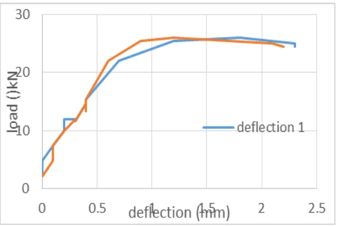
Load vs Deflection Graph
As the load increases the deflection of the beam begins. Load will be directly proportional to deflection. The load values and corresponding deflection beam with replacement at the neutral axis is given in Table 3, 4 & 5.
Table – 3 Compression Beam Load Deflection 1 Deflection 2
1.1 0.1 0.1
1.4 0.1 0.1
1.6 0.1 0.1
1.9 0.1 0.2
1.9 0.2 0.2
2.1 0.2 0.2
2.1 0.5 0.3
2.6 0.5 0.3
2.7 0.6 0.3
2.9 0.9 0.5
3.2 0.9 0.7
3.4 1.2 0.7
3.4 1.2 0.9
3.5 1.2 0.9
3.5 1.3 0.9
4.8 1.1 1.2
10.7 1.1 1.2
15.7 1.3 1.4
15.4 1.3 1.4
21.6 1.5 1.7
26.6 1.8 1.7
25.9 1.8 1.9
25.6 1.9 1.9
26.6 2.1 2
27.5 2.1 2
25.3 2.1 2
24.6 2.2 2.2
24.5 2.3 2.2
24.5 2.4 2.3
Fig: 3: Load vs Deflection Graph
Table – 4 Centroid Beam
Load Deflection 1 Deflection 2
2.7 0.1 0.2
6.2 0.3 0.3
5.3 0.3 0.3
4.8 0.3 0.4
4.6 0.4 0.4
4.6 0.4 0.4
10.4 0.5 0.5
15 0.7 0.7
15.8 0.8 1
15.5 0.8 1
18.4 0.9 1
18.9 1 1.1
18.6 1 1.1
18.2 1 1.1
18.2 1 1.1
18.1 1 1.2
17.8 1 1.1
17.8 1 1.2
21.3 1 1.2
25.4 1.2 1.4
25.4 1.3 1.5
27.2 1.3 1.5
32.6 1.6 1.8
32.3 1.8 2.1
31.8 1.8 2.1
31.5 1.8 2.1
31.2 1.8 2.1
31 1.8 2.1
30.6 1.8 2.1
30.4 1.8 2.1
Fig. 4: Load vs Deflection Graph
Table – 5 Tension Beam
Load Deflection 1 Deflection 2
2.1 0 0
4.8 0 0.1
7.4 0.1 0.1
9.9 0.2 0.2
12 0.2 0.3
12 0.3 0.3
11.7 0.3 0.3
14.7 0.4 0.4
14.2 0.4 0.4
13.6 0.4 0.4
13.6 0.4 0.4
13.3 0.4 0.4
15.4 0.4 0.4
22.1 0.7 0.6
25.4 1.2 0.9
26.1 1.8 1.2
25 2.3 2.1
Fig: 5: Load vs Deflection Graph
Ultimate Load vs Depth of Hollow Core
Table – 6 Ultimate Load
Zone Load
Compression 27.5 Centroid 33.3 Tension 26.1
Fig. 6: Ultimate Load vs Depth of hollow core
Crack Pattern
Fig. 7: crack pattern
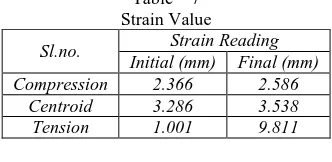
Strain Behavior
Strain value of the beams is shown in table 7. The strain distribution over the cross section is tabulated for the initial and final strain. The highest strain value occur at the centroid zone of the beam. The strain measure in demec gauge in two points the center of the beam along the length side.
Table – 7 Strain Value
Sl.no. Strain Reading Initial (mm) Final (mm) Compression 2.366 2.586
Centroid 3.286 3.538
Tension 1.001 9.811
VIII. CONCLUSIONS
Behavior of reinforced concrete beams with region below the neutral axis with voids created using PVC pipes. Presence of voids instead of concrete in the low stressed zone has not caused significant reduction in strength of reinforced concrete beams. It has been observed that the replacement of concrete by voids in reinforced concrete beams does not require any extra labor or time. Economy and reduction of weight in beam depends on the percentage replacement of concrete. Replaced reinforced concrete beams can be used for sustainable and environment friendly construction as it saves concrete which reduces the emission of carbon dioxide during the production of cement. This work can be further investigated by using different diameter PVC pipe. Several other parameters can also be tested like impact resistance, abrasion, fatigue resistance, etc. The work can be extended in other mixes and also by introducing other weightless inert materials.
It is found that by the use of Glass fiber in the concrete mix increases the load carrying capacity of the beam against normal concrete.
The ultimate load carrying capacity of the beam is high in centroid zone of hollow core when compared to other zones of hollow core.
The compressive strength and split tensile strength of M20 grades of glass fiber concrete mixes compared with 28 days is observed from 10 to 20%.
The highest strain value is also occur in the centroid zone of the beam.
REFERENCES
[1] A.S.Almuaimi and P.Bhatt, “Idealisation of Hollow Reinforced Concrete Beams Subjected To Combined Torsion, Bending and Shear” (Sep-2014), the Journal of Engineering Research, Vol. 2, No. 1.
[2] A.Upendra Varmal and A.D.Kumar, “Experimental Study On The Glass Fibre Reinforced Concrete” (Sep-2013), Int. Journal Of Engineering Research And Applications,Vol.-3,Issue-5,Pg.1914-1918.
[3] Ahmad Jabbar Hussain Alshimmeri, Hadi Nasir Ghadhban Al-Maliki, “Structural Behavior of Reinforced Concrete Hollow Beams under Partial uniformly distribution load” (july-2014), International Journal of Engineering, Vol.20, Pg: 130-145.
[4] Ali Said Alnuaimi Khalifa and S.Aljabri Abdelwahid Hago, “Comparison between Solid and Hollow Reinforced Concrete Beams” (April-2007), Research Gate in Material and Structure, Vol.41, Pg: 269-289.
[5] M.A.A. Saafan, “Behaviour Of Singly Reinforced Concrete Hollow Beams With Gfrp” (2006), International Journal For Research In Applied Science & Engineering Technology, Vol-110, Issue-6, Pg-677-686.
[7] Nibin Varghese and Anup Joy, “Flexural Behavior of Reinforced Concrete Beam with Hollow Core at Various Depth” (May-2016).International Journal Of Science And Research, Vol.5, No.5, Pg-741-746.
[8] R.Elanchezhiyan1, K.Thiyagu and C.Hema, “An Experimental Investigation on Strengthening of Reinforced Concrete Beam Using Glass Fiber reinforced” (Jan-2016), International Journal Of Innovative Research In Science, Engineering And Technology, Vol-5, Issue-1, Pg-453-457.
[9] Sandeep Kumar, L.S,Dr.H.N.Jagannatha Reddy and Rumia Nizar, “Retrofitting of RC Beams using FRP Wrapping” (Sep-2013), International journal of emerging trends in engineering and development, vol-5, issue-3, pg-168-178.