method based on interim state stiffness of
machining features for NC programming of
structural parts
Sen Jiang, Yingguang Li
*and Changqing Liu
Abstract
For thin-walled parts, uniform allowance to each machining surface is allocated by the traditional machining method. Considering the sequence of the adjacent machining features, it may cause poor stiffness for some side walls due to a minor wall thickness, which may cause the deformation of the final formed parts to be large, or deduce machining efficiency for some machining features due to too thick remains. In order to address this issue, a non-uniform allowance allocation method based on interim state stiffness of machining features for the finishing of thin-walled structural parts is proposed in this paper. In this method, the interim state model of machining features is constructed according to the machining sequence of the parts, and the stiffness of the side wall is taken as the evaluation index to allocate reasonable allowance value to the corresponding machining surface to ensure the stiffness requirement of the parts in the machining process. According to the finite element simulation results, the non-uniform allowance
allocation method proposed in this paper can effectively improve the stiffness of the parts and reduce the deformation of the parts, when compared with the traditional uniform allowance machining method.
Keywords:Machining features, NC programming, Interim state, Non-uniform allowance, Stiffness
Background
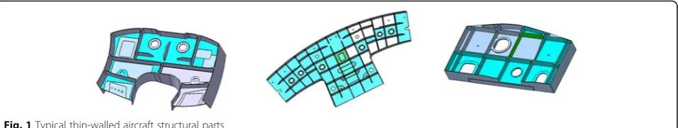
Thin-wall structure is widely used in aircraft structural parts, as shown in Fig. 1. For this kind of parts, the structure is complex and the machining accuracy re-quirement is high. In order to ensure that the final de-formation of thin-walled parts is within machining tolerance, it is necessary to meet the specific require-ment of the part stiffness in the process of machining, especially in the finishing stage of the parts. According to the traditional uniform allowance programming method, all machining surfaces will be allocated the same allowance when finishing, and the effect of pro-cessing sequence among the propro-cessing features is not considered in this process. In fact, the wall thickness of the adjacent machining surface of the adjacent machin-ing features is different when it is processed successively due to the machining sequence difference, and the
stiffness of the post-processing feature may be insuffi-cient when it is processed. Consequently, the deform-ation of the parts may be out of specificdeform-ation, or even the final parts may be scrapped.
Literature review
When thin-walled parts being machined by NC machin-ing, it is difficult to meet the design requirements be-cause of poor stiffness and the deformation be-caused by various machining factors. Therefore, NC machining of thin-walled parts is a bottleneck problem in the machin-ing field. Aimmachin-ing at this problem, many scholars and technicians all over the world have tried and studied the corresponding methods, which can be roughly divided into the following four categories.
Optimization of processing technology route
This kind of method is trying to eliminate the machining stress caused by cutting, clamping and the residual stress of the material itself by setting one or more * Correspondence:[email protected]
College of Mechanical and Electrical Engineering, Nanjing University of Aeronautics and Astronautics, Nanjing, China
semi-finishing and aging processes between rough ma-chining and finishing. It is expected that the deformation of the material only occurs in the final finishing stage. Ren et al. [1] presented an efficient rough machining process for engine blade. In order to prevent the large cutting stress and deformation in rough machining, they carried out the method of dispersing the working processes, exe-cuting aging treatment and benchmark repairing several times to reduce the deformation caused by stress.
Optimization of clamping process: This kind of method attempts to ensure the stiffness of parts in ma-chining process by changing the clamping forms, fixture tools and clamping force, so as to ensure the quality of parts. Wang et al. [2] presented a special fixture for thin-wall parts machining clamping by using low shrink-age and low melting point alloy. The experimental re-sults show that high material removal rate and machining accuracy can be obtained by using this special fixture during the machining process. Considering the influence of clamping sequence on machining accuracy, Qin et al. [3] established a model for analyzing and opti-mizing clamping sequence of parts. This method can re-duce the machining deformation and positioning error by establishing the relation between the distribution of contact force and the machining accuracy of the parts, and finally improve the machining rigidity of the system. Pan et al. [4] constructed the relationship model be-tween clamping point contact force and contact deform-ation by finite element method, meanwhile, the nonlinear relationship between contact force, deform-ation and contact region is quantitatively analyzed, which provides a basis for the analysis of machining de-formation and assembly error of thin-walled parts. Vol [5] proposed an optimization method of the clamping position and clamping point number based on genetic algorithm. The experimental results show that the method can improve the size and shape accuracy of ma-chining parts. Xue et al. [6] put forward a synchronous optimization method of clamping force and cutting pa-rameters based on genetic algorithm and finite element analysis to reduce machining deformation of parts. Sel-vakumar et al. [7] proposed an experimental design method based on artificial neural network. This method can reduce the clamping force and maximize the elastic
deformation in the machining process by optimizing the clamping layout.
Optimization of cutting force and error compensation
This kind of method is trying to reduce the deformation and vibration in the machining process by optimizing the cutting force and error compensation to ensure the form-ing quality of the final part. Qu et al. [8] proposed a multi-objective optimization method to minimize cutting force and maximize machining efficiency. Yang et al. [9] established the mathematical model of cutting force for thin-walled parts of titanium alloy by means of multiple regression and orthogonal test. Moreover, the influence of cutting force on machining deformation has been ana-lyzed, which provides a reference for optimization of cut-ting parameters of difficult-to-machine materials. Zhou et al. [10] studied the nonlinear dynamic behavior of cut-ting force during the machining process of thin plate parts, and the results indicate that the cutting force can develop complicated dynamic behavior due to the time-delay effect. Huang et al. [11] used spectrum analysis and wavelet analysis to analyze and compare the cutting force and spindle acceleration signal between thin-walled and non-thin-walled titanium alloy parts to determine the influence of tool wear on cutting parts. Liu et al. [12] pro-posed a finite-element-based milling error prediction method. This method establishes the dynamic model of the tool in the whole continuous cutting process to obtain the moving state of the tool at any point. Then, the ma-chining error of the parts surface can be obtained. Chen et al. [13] presented a method of active compensation for machining error of thin-walled parts. The method estab-lishes a multi-layer cutting deformation model of thin-walled parts and realizes the compensation of ma-chining error by layer-by-layer iterative calculation. Cui et al. [14] proposed a software error compensation method by reconstructing NC program. The experimental results indicate that the reconstruction of NC program can effectively improve the motion accuracy of NC ma-chine tools. Liu et al. [15] proposed a comprehensive com-pensation method for machining errors of aircraft thin-walled parts. The method acquires the contour infor-mation of parts by mechanical scanning method and then establishes a unified target for model reconstruction. The Fig. 1Typical thin-walled aircraft structural parts
experimental results show that the dimension feedback technique can effectively improve the machining quality and efficiency. Zhang et al. [16] proposed an adaptive compensation method for blade machining accuracy based on machine measurement. Simultaneously, an adap-tive geometric model of machining parts was established by analyzing and comparing the calibration model with
the real measurement data. It is used to accurately de-scribe the machining accuracy of thin-walled blade with compound error compensation.
Introduction of non-traditional processes
With the development of machining technology, some non-traditional machining techniques have been applied Fig. 2Basic idea of the proposed method
to the numerical control machining of thin-walled parts, among which ultrasonic vibration cutting and high-speed cutting are the most representative. Jiao et al. [17] have studied ultrasonic vibration machining. The results show that elliptical vibration cutting has many advantages: when the vibration frequency and amplitude increase, the cutting force and cutting temperature will decrease, and the surface quality of the parts can be improved accord-ingly, at the same time, the burrs caused by machining are limited to specific regions, which is suitable for thin-walled parts. Shamoto et al. [18] has developed a kind of TDF
(Three Degree of Freedom) ultrasonic vibration equip-ment, which can produce arbitrary ultrasonic elliptical vi-bration in three-dimensional space, and it is very suitable for NC machining of 3D complex thin-walled parts. Nath et al. [19] put forward the concept of contact rate in ultra-sonic vibration machining by studying parameters vibra-tion frequency, vibravibra-tion amplitude and cutting speed. The experimental results show that contact rate has an import-ant influence on cutting force and tool wear. Yin et al. [20] designed a kind of single-drive ultrasonic elliptical vibra-tion cutting equipment. The experimental results show Fig. 4Diagram of machining feature interim state construction
Fig. 5Wall thickness calculation process of machining surface
that the device can reduce the cutting force and the sur-face roughness of the parts. By modifying the Cook model and simulating the cutting force, cutting shape, effective stress and cutting temperature of thin-walled parts, Tang et al. [21] established a finite element simulation model for high-speed milling, which provides a new idea for the deformation control of thin-walled parts.
The above methods can improve the machining quality of thin-walled parts from the aspects of machining process, clamping, fixture tool, error compensation, etc. However,
few studies have focused on the structural characteristics and machining stiffness optimization of thin-walled parts.
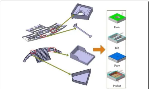
In order to solve the deformation problem caused by the lack of local stiffness of thin-walled parts caused by uniform allowance programming, a non-uniform allowance allocation method based on interim state stiffness of machining fea-tures is proposed in this paper. In this method, the interim state model of machining features is constructed according to the machining sequence of parts, and the stiffness of the corresponding machining surface is taken as the measuring Fig.6A typical thin-walled structural part
index to assign reasonable finishing allowance value to the machining surface. The basic idea of this method is shown as Fig.2.
Methods
Evaluation method of interim state stiffness of machining features
Interim state of machining features
As the carrier of process knowledge, machining features can obviously improve the efficiency and standardization of ma-chining process preparation and reduce the influence caused by process experience of personnel, and thus improve the stability of processing quality. In feature-based process scheme, using machining features instead of the whole en-tity parts model can make information be expressed clearer and more structured. For complex thin-walled structures, it is basically composed of typical machining features such as pockets, ribs and holes, as shown in Fig.3.
Each machining feature corresponds to the specific machining operation in the forming process. There-fore, in order to process the stock into the final part, many machining operations are required. A corre-sponding interim state of machining feature will be formed after each machining operation is completed. The geometric shape of feature interim state will be changed according to the change of machining al-lowance. Each interim state of machining feature is
the result of the last machining feature interim state, and the next machining interim state is produced after the corresponding machining operation. Figure 4 shows the construction process of the interim state of machining fea-tures in the machining process.
For the finishing process of thwalled parts, the in-terim state geometry of machining features can be repre-sented as the model geometry after rough machining minus the machining units of machined features:
PG¼RG−Xk
i¼1
FGi ð1Þ
In the formula PGdenotes the interim state geometry of the current machining feature,RGdenotes the model geometry after rough machining,FGidenotes the
geom-etry of the finishing machining unit of the i-th machin-ing feature,kdenotes the number of machined features.
Stiffness evaluation method
The surface stiffness of the machining feature is an im-portant basis for the allocation of non-uniform allow-ance. How to evaluate the stiffness of each machining surface is a crucial issue. According to the relevant stiff-ness theory and practical experience, we can easily know that the thicker the side wall the better the stiffness and the larger the surface area the worse the stiffness. Based Fig.8A pocket feature of the thin-walled part
on the above two points, a surface stiffness index of ma-chining featureεis presented in this paper for the complex thin-walled structural parts, which can be shown as:
ε¼Aδ104 ð2Þ
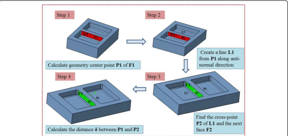
In the formulaδdenotes the wall thickness of machin-ing surface in the current interim state of machinmachin-ing fea-tures, A denotes the area of machining surface. The method for calculating the wall thickness of the machin-ing surface follows the process shown as Fig.5.
Algorithm of non-uniform allowance allocation method
Based on the concept of surface stiffness index of ma-chining feature, a non-uniform allowance allocation al-gorithm for finishing of thin-walled structural parts is proposed. The steps of the algorithm are as follows:
(1) According to the geometric model of parts and the machining requirements, the reasonable range of machining allowance is set by the relevant technicians, that is the maximum machining allowanceZmaxand the minimum machining allowanceZmin;
(2) Calculate the wall thicknessδiand areaAiof each machining surface for the current machining feature. Then we can get the corresponding surface stiffness indexεi. Using all of the surface stiffness indexes, we can get the average stiffness index of the machining feature, which can be shown as:
εavg¼
Xn
i¼1
εi
n ð3Þ
In the formula εavg denotes the average stiffness
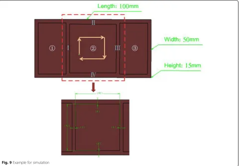
index of the current machining feature, n denotes Fig. 9Example for simulation
Table. 1Basic information of the part
Material Elastic modulus /GPa Poisson’s ratio Length /mm Width /mm Height /mm Depth of pocket /mm
the number of machining surfaces in the machining feature.
(3) In order to equalize the stiffness of each machining surface, by comparing the stiffness index of each machining surface with the average stiffness index, the finishing allowance of each machining surface is adjusted appropriately, which can be represented by the following formula:
Zi¼
Zmin;Zi<Zmin
Zoiþ εavg−εi
Zoi
εmax−εmin ;Zmin≤Zi≤Zmax
Zmax;Zi>Zmax
8 > < >
: ð4Þ
In the formula Zi denotes the adjusted allowance
value, Zoi denotes the original allowance value, εmax
denotes the maximum surface stiffness index of the current machining feature, εmin denotes the minimum
surface stiffness index of the current machining feature.
Results and discussion
In order to validate the proposed non-uniform allowance allocation method, a thin-walled structural part shown as Fig.6is adopted as a case study.
Implementation process
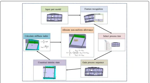
The whole implemented process can be described as Fig. 7.
Step 1: Input the part model and execute the process of feature recognition. By analyzing the structural and machining characteristics of the part, divide the machin-ing features into several classifications.
Step 2: Select process tree and obtain the machining operations related to the machining features. Then, we can find the corresponding relationship between ma-chining operations and mama-chining features according to the machining feature identifiers. And then according to the sequence of machining operations in the process Fig. 10Simulation result of side wallI
Fig. 11Deformation comparison of two methods
tree, the machining sequence of machining features is obtained.
Step 3: According to the machining sequence of ma-chining features, construct the interim mama-chining states successively. The interim machining state geometry cor-responding to the current machining feature is con-structed by the current machining feature geometry overlying the finishing allowance. Then the interim ma-chining state geometry corresponding to each mama-chining feature can be obtained by analogy.
Step 4: Aiming at the interim machining state geom-etry of each machining feature, calculate the stiffness index εi of each machining surface according to the
method mentioned above. Take one pocket feature out of the thin-walled part to validate the allowance alloca-tion process, which can be shown as Fig.8.
Assuming that the allowance range of machining fea-ture to be processed is 0.5 mm~ 2 mm and the initial uniform finishing allowance Zoi= 1.2 mm according to
the relevant machining process requirements. The side wall thickness corresponding to each machining surface can be calculated as follows: 4 mm, 3 mm + 1.2 mm, 4 mm, 3 mm. Then according to formulas (2), (3) and (4), we can calculate the corresponding stiffness index of each surface is 7.41, 8.53, 7.41, 9.95, the average value of stiffness index of machining feature is εavg= 8.33, and
the allowance after adjustment of each machining sur-face is 1.63 mm, 1.11 mm, 1.63 mm, 0.43 mm.
Step 5: After obtaining the adjusted non-uniform al-lowance of each machining surface, the new machining drive geometries can be generated by offsetting allow-ance value based on the original ones.
Simulation analysis
To verify the effectiveness of the proposed method in improving the machining stiffness of parts, a thin-walled part with three pockets (shown as Fig. 9) is adopted to do the finite element simulation on ABAQUS. The basic
information for the part is shown in the Table.1, and the machining sequence of the three pockets in the part is clockwise. Take the four walls of the middle pocket out to carry out finite element analysis. In the simulation, we set uniform distributed load at 500 Pa with three-terminal fixed constraint.
Assuming that the reasonable allowance range is 0.5 mm to 2 mm and the initial uniform allowance is 1.2 mm. According to the proposed method, the ad-justed allowance values of the four walls areZ1= 2 mm,
Z2= 0.87 mm,Z3= 0.9 mm,Z4= 0.9 mm.
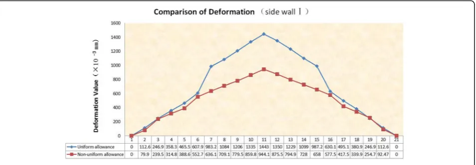
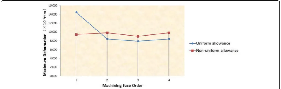
It is easy to know that the first side wall is the worst in stiffness by the proposed method. If the maximum value of its deformation is within the required range, the amount of deformation of the remaining three side walls is also within the required range. As shown in Fig. 10, select the 21 reference points along the horizontal direc-tion to draw the deformadirec-tion trend map of different po-sitions of the first side wall. In the same way, we use the same load and constraint to simulate the deformation of the first side wall under the non-uniform allowance method. We can easily find that the maximum deform-ation is located at the middle point on the top surface of the side wall. It is obvious that the deformation at each reference point of the non-uniform allowance method is smaller than that of the uniform allowance method when compared the deformation of these two methods (shown as Fig. 11), and the maximum deformation de-creases from the original 1.443 mm to 0.944 mm, which means a reduction by 34.6%.
smaller than the maximum deformation of the first side wall under the uniform allowance allocation method.
Conclusions
The machining of thin-walled parts is a crucial issue to NC machining. The traditional method will allocate uni-form finishing allowance to each machining surface, which will easily leads to insufficient wall thickness and poor stiffness of some machining surfaces, resulting in excessive deformation of the final formed parts, or de-duce machining efficiency for some machining features due to too thick remains. In order to solve this problem, a non-uniform allowance allocation method based on in-terim state stiffness of machining features for thin-walled parts finishing is proposed in this paper. Ac-cording to the evaluation of interim state stiffness of each machining feature, the non-uniform allowance is allocated to ensure the stiffness requirement in the fin-ishing process. The finite element simulation results re-veals that the non-uniform allowance allocation method proposed in this paper can effectively guarantee the stiff-ness of the parts and reduce the deformation of the parts compared with the traditional uniform allowance alloca-tion method.
Although the results are promising, there is still much room for improvements. In the above proposed method, the stiffness index is simplified to be proportional to the area and thickness of the machining surface. This may not be suitable for some complex compound features. Our future work will focus on exploring a more accurate stiffness evaluation method for complex machining features.
Acknowledgements
The research work presented in this paper was primarily supported by the National Science and Technology Major Project of the Ministry of Science and Technology of China (No. 2015ZX04001002).
Authors’contributions
All authors read and approved the final manuscript.
Competing interests
The authors declare that they have no competing interests.
Publisher’s Note
Springer Nature remains neutral with regard to jurisdictional claims in published maps and institutional affiliations.
Received: 20 March 2018 Accepted: 20 June 2018
References
1. Ren JX, Zhang DH, Wang ZQ, Liu WW, Wang WH. Research on the NC machining technique of blisk. Acta Aeron Astronaut Sin. 2004;25:205–8. 2. Wang T, Zha J, Jia Q, Chen YL. Application of low-melting alloy in the
fixture for machining aeronautical thin-walled component. Int J Adv Manuf Technol. 2016;87:2797–807.
3. Qin GH, Zhang WH, Wan M. Analysis and optimal design of fixture clamping sequence. J Manuf Sci Eng. 2006;128:482–93.
4. Pan MH, Tang WC, Xing Y, Ni J. The clamping position optimization and deformation analysis for an antenna thin wall parts assembly with ASA, MIGA and PSO algorithm. Int J Precis Eng Manuf. 2017;18:345–57. 5. Liao YC. A genetic algorithm-based fixture locating positions and clamping
schemes optimization. Proc Inst Mech Eng B J Eng Manuf. 2003;217:1075–83. 6. Xue LF, Chen WF, Feng T, Ma WT. Synchronous optimization of clamping
force and cutting parameters for thin-walled parts. Adv Mater Res. 2014;900: 623–6.
7. Selvakumar S, Arulshri KP, Padmanaban KP, Sasikumar KSK. Design and optimization of machining fixture layout using ANN and DOE. Int J Adv Manuf Technol. 2013;65:1573–86.
8. Qu S, Zhang MQ. Optimization for cutting force and material removal rate in milling thin-walled parts. In: Proceedings of the 4th International Conference on Advanced Materials and Information Technology Processing. Phuket: Atlantis Press; 2016.
9. Yang YH, Guo JY, Yu C. Analysis to the influences of cutting force to machining deformation of a titanium alloy thin-wall tube. Adv Mate Res. 2012;366:510–3.
10. Zhou R, Zhang W, Zu JW. Analysis on nonlinear dynamics of a thin-plate workpiece in milling process with cutting force nonlinearities. J Mech Sci Technol. 2014;28:2511–26.
11. Huang PL, Li JF, Sun J, Jia XM. Cutting signals analysis in milling titanium alloy thin-part components and non-thin-wall components. Int J Adv Manuf Technol. 2016;84:2461–9.
12. Liu SM, Shao XD, Ge XB, Wang D. Simulation of the deformation caused by the machining cutting force on thin-walled deep cavity parts. Int J Adv Manuf Technol. 2017;92:3503–17.
13. Chen WF, Xue JB, Tang DB, Chen H, Qu SP. Deformation prediction and error compensation in multilayer milling processes for thin-walled parts. Int J Mach Tools Manuf. 2009;49:859–64.
14. Cui GW, Lu Y, Li JG, Gao D, Yao YX. Geometric error compensation software system for CNC machine tools based on NC program reconstructing. Int J Adv Manuf Technol. 2012;63:169–80.
15. Liu HB, Wang YQ, Jia ZY, Guo DM. Integration strategy of on-machine measurement (OMM) and numerical control (NC) machining for the large thin-walled parts with surface correlative constraint. Int J Adv Manuf Technol. 2015;80:1721–31.
16. Zhang Y, Zhang DH, Wu BH. An adaptive approach to error compensation by on-machine measurement for precision machining of thin-walled blade. In: Proceedings of 2015 IEEE international conference on advanced intelligent mechatronics. Busan: IEEE; 2015. p. 1356–60.
17. Jiao F, Zhao B, Liu CS, Gao GF. Research on influence of cutting conditions on roundness of ultra-thin wall parts in ultrasonic vibration cutting. J Xiamen Univ (Nat Sci). 2002;41:75–6.
18. Shamoto E, Suzuki N, Tsuchiya E, Hori Y, Inagaki H, Yoshino K. Development of 3 DOF ultrasonic vibration tool for elliptical vibration cutting of sculptured surfaces. CIRP Ann. 2005;54:321–4.
19. Nath C, Rahman M. Effect of machining parameters in ultrasonic vibration cutting. Int J Mach Tools Manuf. 2008;48:965–74.
20. Yin Z, Fu YC, Xu JH, Li H, Cao ZY, Chen YR. A novel single driven ultrasonic elliptical vibration cutting device. Int J Adv Manuf Technol. 2017;90:9–12. 21. Tang DW, Peng RS, Zhao RL. Numerical simulation study of high-speed
milling thin-wall part. Adv Mater Res. 2011;239–242:801–5.