The Stability of Flute Modes in the GAMMA10 A-divertor
∗
)
Isao KATANUMA, Kotaro YAGI, Yusuke HARAGUCHI, Nobuyuki ICHIOKA, Shun MASAKI,
Shuhei SATO, Kazuto SEKIYA, Makoto ICHIMURA and Tsuyoshi IMAI
Plasma Research Center, University of Tsukuba, 1-1-1 Tennoudai, Tsukuba, Ibaraki 305-8577, Japan
(Received 29 November 2010/Accepted 16 February 2011)
The linear growth rates of flute instability are investigated in the GAMMA10 A-divertor magnetic geometry. It is found that the minimum-B in the remaining anchor cell can stabilize the flute mode even in the GAMMA10 A-divertor which contains an axisymmetric divertor mirror cell, although the flute modes are not stabilized in case of weak magnetic well.
c
2011 The Japan Society of Plasma Science and Nuclear Fusion Research
Keywords: flute mode, interchange mode, mirror, MHD, simulation DOI: 10.1585/pfr.6.2403080
1. Introduction
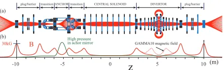
The GAMMA10 tandem mirror is planning to replace one anchor cell with an axisymmetric divertor mirror cell, which is called “the GAMMA10 A-divertor” at present shown in Fig. 1. The main purpose of installing a diver-tor mirror cell is to perform the simulation experiments of a divertor of a big torus such as LHD and ITER.
We are here interested in the stability of the flute mode in the GAMMA10 A-divertor. The min.B mirror and the divertor mirror in the GAMMA10 A-divertor have a diff er-ent flute mode stability mechanism with each other. That is, there are the good magnetic field line curvatures in the anchor cell, but the bad curvatures in the divertor mirror in the core region. The long thin approximation of magnetic field lines can be applied to the anchor mirror, but not to the divertor mirror.
It is known that the flute mode is stabilized mainly by the plasma compressibility in a divertor mirror [1,2], while it is stabilized by the good magnetic field line curvature in the min.B anchor mirror cell [3]. The stability boundary of the flute modes was found to depend on the radial pro-files of mass density and temperature in an axisymmetric divertor mirror [1, 2].
Fig. 1 GAMMA10 A-divertor. (a) is the magnetic field lines with coils and (b) is the axial magnetic field and pressure profiles.
author’s e-mail: [email protected]
∗)This article is based on the presentation at the 20th International Toki
Conference (ITC20).
The GAMMA10 A-divertor requires the three-dimensional treatment for the flute mode linear analysis. There are the basic equations for the flute mode fluctua-tions which are applicable to the axisymmetric magnetic field including divertor mirror cell [4, 5]. In the paper we carry out the stability analysis by extending the equations to the GAMMA10 A-divertor.
2. Basic Equation
The flute mode stability criterion in the open systems such as a tandem mirror is given by [3],
[ ˆp⊥(χ)+pˆ(χ)]κψ
B2 dχ≥0. (1)
Here the curvature of a magnetic field line is represented by the covariant componentsκ(≡eˆ· ∇eˆ)=κψ∇ψ+κθ∇θ, where the coordinates (ψ, θ, χ) satisfyB=∇ψ× ∇θ=∇χ. The components, parallel and perpendicular to the mag-netic fieldB, of plasma pressure p,⊥ are described by a separation of variablesp,⊥(ψ, χ)=pˆ,⊥(χ)ν(ψ). Note that Eq. (1) can be applied to the non-axisymmetric mirror such as GAMMA10.
In the case of isotropic pressure the stability criterion (1) is written as
∂U ∂ψ =−2
κ
ψ
B2 dχ≤0. (2)
HereUis the specific volume of a magnetic field line de-fined by
U=
1
B2 dχ, (3)
and the relation∇⊥B = Bκ, which holds in the vacuum magnetic field, was used to obtain Eq. (2).
Equation (2) indicates that∂U/∂ψrepresents the effect of a magnetic field line curvature. That is, if∂U/∂ψ ≤0 then there is a magnetic well having the stabilizing effects
c
2011 The Japan Society of Plasma
on the flute modes. Namely, the specific volume of a mag-netic field line includes the effect of the magnetic field line curvature.
For the purpose that the equations derived on the assumption of axisymmetric magnetic field are applied to the non-axisymmetric (but effectively axisymmetrized) GAMMA10 A-divertor, the specific volumeUis redefined as
U=
ˆ
p⊥(χ)+pˆ(χ)
B2 dχ . (4)
Equation (4) assures that the condition of magnetic well
∂U/∂ψ≤0 gives the same stability criterion as Eq. (1). The basic equations (the reduced MHD equations) for flute mode fluctuations are written as [4, 5]
∂wˆ
∂t +[[Φ,wˆ]]−[[ ˆρ, v2
α 2 ]]+
1
Uγ ∂U ∂ψ
∂ρˆTˆ
∂θ ={DT},
(5)
∂ ∂ψ
ˆ
ρr2 ∂ ∂ψΦ +∂θ∂ ˆ ρ 1
r2B2+λ 2
B2
∂
∂θΦ
=wˆ, (6)
∂ρˆ
∂t +[[Φ,ρˆ]]={DT}, (7)
∂Tˆ
∂t +[[Φ,Tˆ]]={DT}. (8)
The symbol{DT}s in the right hand side in Eqs. (5), (7), (8) represent the diffusion terms resulting from the clas-sical viscosity, resistivity and conductivity. The quantity
ˆ
T is defined as ˆT ≡ (Ti +Te)U2/3/Mi where Ti (Te) is
the ion (electron) temperature and Mi is ion mass, ˆρ is
defined as ˆρ ≡ ρU where ρ is mass density, ˆw is de-fined as ˆw = wU where w is the plasma vorticity de-scribed in Eq. (6), Φ is the electrostatic potential, vα is the plasma adiabatic velocity, γ is specific heat index. The symbol A means the average quantity of A along a magnetic field line, i.e., A ≡ (1/U)(A/B2)dχ and λ=U(∂/∂ψ)(0χ[1/UB2]dχ)+(∇ψ· ∇χ)/(r2B4). The no-tation [[ ]] defined by the equation,
[[A,B]]≡ ∂A 2x∂x
∂B ∂ϕ −
∂A ∂ϕ
∂B
2x∂x, (9)
is known as the Poisson bracket and this term represents the convectiveE×Bflow term in Eqs. (5)–(8).
Although Eqs. (5)–(8) are derived on the assumption of the axisymmetric magnetic field, we apply these equa-tions to the effectively axisymmetrized GAMMA10 A-divertor by changing the specific volume of a magnetic field line to Eq. (4)
3. Non-local Linear Analysis
Henceforth all variables are normalized asD=ρ/ˆ ρˆM,
T =Tˆ/TˆM,w=wˆψb/ρMUMbcsM,φ= Φb/csMψb. Here
subscriptMmeans the quantity at the midplane of a divertor
mirror cell,ψbis the coordinate at the separatrix (x-point),
csis sound speed,b=
ψb/BM,x=
ψ/ψb,ϕ=θ,is
the small expansion parameter which are used to obtain Eqs. (5)–(8), where we assume2=10−2in the paper.
The variables are divided into the equilibrium quanti-ties and the perturbed quantiquanti-ties as
D(x, ϕ)=DE(x)+2 m0Df(m)(x) exp{imϕ−iωτ}, T(x, ϕ)=TE(x)+2 m0Tf(m)(x) exp{imϕ−iωτ}, w(x, ϕ)=w0(x)+ m0wf(m)(x) exp{imϕ−iωτ},
φ(x, ϕ)=φ0(x)+ m0φ(m)(x) exp{imϕ}, (10)
whereτ = tcsM/b is the normalized time and mis the
azimuthal mode number.
The non-local linear dispersion equation is obtained by linearizing Eqs. (5)–(8) with neglect of the terms{DT},
∂ ∂x
⎧⎪⎪ ⎪⎪⎩DEf1
x ∂φ(m)
∂x
⎫⎪⎪ ⎪⎪⎭−∂∂
x
m f1
2x2φ(m) ∂φ0
∂x ∂DE
∂x
⎧ ⎪⎪⎪⎪⎩ω− m
2x ∂φ0
∂x
⎫⎪⎪ ⎪⎪⎭
−⎧⎪⎪⎪⎪⎩4xDE(f3+f4)m2+
4xwf(m) φ(m)
⎫⎪⎪
⎪⎪⎭φ(m)=0, (11)
whereφ0(x) is determined by
∂ ∂x
⎧⎪⎪ ⎪⎪⎩DEf1
x ∂φ0
∂x
⎫⎪⎪
⎪⎪⎭=4xw0, (12) and the last term in left-hand side of Eq. (11) is written as
4xwf(m) φ(m)
=−m2
2x ∂(V2)(0)
∂x ∂DE
∂x
⎧ ⎪⎪⎪⎪⎩ω−m
2x ∂φ0
∂x⎫⎪⎪⎪⎪⎭ 2
−2m∂w0 ∂x
⎧ ⎪⎪⎪⎪⎩ω−m
2x ∂φ0
∂x⎫⎪⎪⎪⎪⎭ (13)
−3m2
52x
1
u5/3 ∂u ∂x
∂(DETE)
∂x
⎧ ⎪⎪⎪⎪⎩ω−m
2x ∂φ0
∂x
⎫⎪⎪ ⎪⎪⎭2.
Here (V2)0 = 2π12c2
sM
v2αdϕ, f1 = r
2
b2 , f3 = B
2
Mb
2
B2r2,
f4 = λ2B2B2mb2. The specific volume is normalized to
beu(x)≡U(x)/U(0).
Because Eq. (11) is the second order differential equa-tion with the eigen-valueω, Eq. (11) can be solved on the boundary conditionφ(m)(x=0)=0 andφ(m)(x=1)=0 with
help of a shooting method numerically, where the condi-tionφ(m)(x=1)=0 comes from the effect of the electric
short circuit along azimuthal magnetic null line.
4. Specific Volume
U
The axial pressure profile is assumed to be ˆ
p(χ)≡pˆ⊥(χ)+pˆ(χ)=max⎧⎪⎪⎪⎪⎪⎩pA
(B2
m−B2)
(B2
m−B2c)
, 1⎫⎪⎪⎪⎪⎪⎭, (14) wherepAis the pressure at the anchor midplane; Bcis the
magnetic field at the midplane on axis in anchor cell and
Bm=1.7Bc,B=B(χ) is the magnetic field on axis, and the
Fig. 2 Axial pressure ˆpand magnetic fieldBprofiles at various radii.
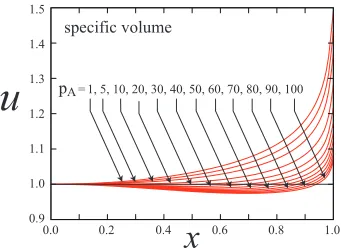
Fig. 3 Radial profiles of normalized specific volumeu(x).
The specific volumeu(x) defined by Eq. (4) is plotted for variouspA in Fig. 3, whereu(x) is the same as Eq. (3)
in the case ofpA = 1. There is the magnetic well in the
core region x <∼ 1/2 for pA >∼ 30. Although u(x)
be-comes infinitely large at the separatrix, the coordinatexis cut offjust before the separatrix for the numerical problem in Fig. 3.
Now the flute modes stability criterion is mentioned in the following briefly [6]. The plasma internal energy in the unit magnetic flux tube isQp=pU/(γ−1), where uniform
pressurepis assumed. The exchange of two neighboring magnetic flux tube with the same unit magnetic flux gives the change of the internal energy,
δQp=δpδU+γp
(δU)2
U . (15)
In the long thin device such as GAMMA10, where
|δp/p| |δU/U|is satisfied, the stability criterion is given by
δQpδpδU≥0. (16)
The stability criterion is δU ≤ 0 because δp < 0 in the real experimental device, which gives the same stability criterion as Eq. (1).
On the other hand, there is the regionU→ ∞in the neighborhood of x-point of a divertor mirror cell, where
|δp/p| |δU/U|is expected. The stability criterion in this case is written as
δQp= δU
Uγδ(pU
γ)≥0. (17)
The radial profile of the normalized specific volume
u(x) in Fig. 3 has a minimum point atx0.55 for the case of pA = 50, while there is a minimum at x 0.50 for
pA = 40. In order to satisfyδQp ≥ 0 everywhere in the
Fig. 4 Radial profiles ofDE(x) andTE(x) for various parameters ofnin Eq. (18).
Fig. 5 Linear growth rateωiofm=1 flute mode.
case ofpA =50,∂(puγ)/∂x≤0 in the good magnetic field
line curvature region ofx <0.5, while∂(puγ)/∂x≥ 0 in the bad curvature region ofx>0.5.
5. Numerical Results of
m
=
1 Flute
Mode
One problem is to make clear how strong the min.B anchor cell can stabilize the flute mode for the experimen-tally expected pressure radial profile in the GAMMA10 A-divertor. The radial profiles of DE(x) and TE(x) are
as-sumed to be
DE(x)=(1−xn)u(x), TE(x)=(1−xn)u(x)2/3,
(18) the profiles of which are plotted in Fig. 4 for the case of
pA =50.
The radial profiles ofDE(x) andTE(x) are the
mono-tonically decreasing functions of x in Fig. 4 except for
n = 20 in Eq. (18). In the case of n = 20 bothDE(x)
andTE(x) have a local minimum atx∼0.5.
Figure 5 plots the growth rateωiofm=1 flute
insta-bility as a function of pA, which was obtained by solving
Eq. (11) withDE(x) andTE(x) in Eq. (18). It is found that
the growth rateωi becomes smaller as pA is larger; the
m= 1 flute mode is stable in the range of pA >∼60. The
radial profiles ofDE(x) andTE(x) in Fig. 4 are the unstable
profile to the flute modes in the divertor mirror only. There-fore, the min.B anchor mirror stabilizes the flute modes in the GAMMA10 A-divertor for pA >∼ 60. As mentioned
in the previous section, however, the specific volumeu(x) shown in Fig. 3 indicates that magnetic well (min.B) region exists for pA >∼ 30. That is, a shallow magnetic well can
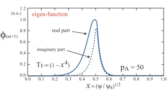
Fig. 6 Eigen-function ofm=1 flute mode.
Fig. 7 A modeled single divertor mirror [4].
Fig. 8 Linear growth rateωiofm=1 flute mode.
The growth rate is lower asnis bigger in Fig. 5. Note thatDE(x)TE(x) ∝ pUγ. The radial profile with biggern
approachesDE(x)1 andTE(x)1, that ispUγconst,
which is a marginally stable profile to the flute mode as shown in Eq. (17). Thus the growth rate becomes lower with the radial profile of a biggern.
Figure 6 plots the eigen-function of them = 1 flute instability in the case ofn=4 andpA=50, which is
local-ized aroundx∼0.5 with a peak just outside the magnetic well (∂u/∂x<0).
If puγ =consteverywhere, the stability condition of flute modes is satisfied and the system is a marginally sta-ble state. However, the classical transport is very large around x-point and sopuγ=constbreaks around x-point. A question is that whether the magnetic well can stabi-lize the flute mode in such the pressure radial profile. We have performed the numerical simulation in the modeled single divertor mirror shown in Fig. 7, which is found in Ref. 4. In the linear growing phase of the flute instability we observed the radial profiles in the simulation [Eq. (28) in Ref. 4].
Figure 8 plots the linear growth rateωi of them =1 flute instability, where the radial profiles ofw0(x),DE(x),
TE(x), observed in the simulation [Eq. (28) in Ref. 4], were
used. The remarkable point is that the flute instability is not stabilized by the magnetic well at all. The reason that the growth rate decreases withpAin Fig. 8 is that the gradient
Fig. 9 Radial profiles ofDE(x) andTE(x) observed in the simu-lation [7].
of specific volume atx>∼0.7 decreases withpAin Fig. 3.
It is found in Figs. 5 and 8 that the stabilizing ef-fects of min.B anchor cell on the flute modes depend strongly on the radial profile ofDE andTE.
Experimen-tally, plasma is sustained by gas puffing and externally in-jected micro-wave, that is the radial profile control is not so easy. Recently we obtained the results shown in Fig. 9 in the GAMMA10 A-divertor magnetic geometry, where the computer simulation was performed by solving Eqs. (5)– (8) with the initial conditions ofDE(x)=1,TE(x)=1 [7].
Figure 9 is the radial profiles of DE andTE in the
quasi-steady state, where plasma continues to be lost ra-dially by the classical transport. The radial profiles in
x >∼ 0.45 is unstable to the flute mode in the divertor, while those in x <∼ 0.45 are stable in the min.B. That is, the flute modes are stabilized by the min.B anchor clearly in the GAMMA10 A-divertor. We, therefore, ex-pect that the min.B anchor can stabilize the flute modes in the GAMMA10 A-divertor even with a magnetic divertor.
6. Summary and Discussion
We calculate the linear growth rate of them=1 flute mode for various radial profile of mass density and tem-perature in the GAMMA10 A-divertor. The GAMMA10 A-divertor contains a min.B anchor mirror cell and an axi-symmetric divertor mirror cell. The flute modes are sta-bilized by a good magnetic field line curvature in an an-chor mirror cell, while these are stabilized by mainly the plasma compressibility in a divertor mirror cell where the magnetic field line curvature is bad.
It is found that there is a radial profile of mass density and temperature wherepUγ=constin the magnetic well, in the profile of which the min.B mirror can not stabilize the flute modes at all.
As long as the pressure radial profile is a monotoni-cally decreasing function in the min.B region, the min.B mirror can stabilize the flute modes. It is also found that the shallow magnetic well, however, does not stabilize the flute modes even in the monotonically decreasing pressure radial profile.
The previous works [4, 7] have defined the specific volume as
U=
ˆ
p⊥(B)+pˆ(B)
instead of Eq. (4). That is, the plasma pressures are represented by p⊥,(ψ,B) = pˆ⊥,(B)ν(ψ) in the MHD analysis [3]. The reason that B was used one of axes in the MHD analysis is to take into account the plasma current along a magnetic field line [8]. How-ever, Eq. (19) gives∂U/∂ψ=[ ˆp⊥(B)+pˆ(B)]κψdχ/B2+
⎧⎩∂[ ˆp⊥(B)+pˆ(B)]/∂ψ⎫⎭dχ/B2, which includes the un-necessary term for the stability criterion. Equation (19) is valid in the paraxial approximation. Therefore the co-ordinates (ψ, θ, χ) are used in the present paper to take into account the flute stability criterion in Eq. (1) exactly in the non-paraxial divertor mirror. The results in the present paper revealed that the linear phase of the flute instability was almost the same as those in the previous works [4, 7].
[1] V.P. Pastukhov and A.Yu. Sokolov, Fiz. Plasmy17, 1043 (1991) [Sov. J. Plasma Phys.17, 603 (1991)].
[2] Y. Sasagawa, I. Katanuma, Y. Mizoguchi, T. Cho and V.P. Pastukhov, Phys. Plasmas13, 122506 (2006). [3] T.B. Kaiser and L.D. Pearlstein, Phys. Fluids 26, 3053
(1983).
[4] I. Katanuma, K. Yagi, Y. Nakashima, M. Ichimura and T. Imai, Phys. Plasmas17, 032303 (2010).
[5] V.P. Pastukhov, Fiz. Plazmy31, 628 (2005) [Plasma Phys. Rep.31, 577 (2005)].
[6] for example, Kenyo Miyamoto, Plasma Physics for
Nu-clear Fusion(Cambridge, Mass.: MIT Press, c1979).