1)EcoTopia Science Institute, Nagoya University, Furo-cho, Chikusa-ku, Nagoya 464-8603, Japan 2)Department of Energy Engineering and Science, Graduate School of Engineering,
Nagoya University, Furo-cho, Chikusa-ku, Nagoya 464-8603, Japan
3)Department of Electrical and Electronics Engineering, Graduate School of Engineering,
Aichi Institute of Technology, Yakusa-cho, Toyota 470-0392
4)Department of Electrical and Electronic Engineering, Graduate School of Natural Science,
Kanazawa University, Kakuma-cho,Kanazawa 920-1192, Japan
(Received 7 May 2009/Accepted 1 December 2009)
Oxy-combustion generates a high temperature field (above 3000 K), which is applied to next generation power plants and high temperature industrial technologies because of N2free processes. However, the combustion
temperature is so high that the furnace wall may be fatally damaged. In addition, it is very difficult to control the heat flux and chemical species’ concentrations because of rapid chemical reactions. We have developed a new method for controlling the flame by electromagnetic force on this field. In this paper, we experimentally investigated the power coupling between the premixed oxy-combustion with methane and radio frequency (RF) power through the induction coil. By optimizing the power coupling, we observed that the flame can absorb RF power up to 1.5 kW. Spectroscopic measurements also showed an increase in the emission intensity from OH radicals in the flame, indicating improved combustibility.
c
2010 The Japan Society of Plasma Science and Nuclear Fusion Research
Keywords: oxy-combustion, plasma assisted combustion, RF inductive plasma DOI: 10.1585/pfr.5.010
1. Introduction
Combustion is a chemical reaction that generates a huge amount of heat formation. This chemical reaction continues voluntarily through active species. In industrial plants, high temperature exothermic reactions are applied widely, and are generated by the oxidation reaction of hy-drocarbon and air. Air combustion generates large amounts of NOXbecause there is much N2in the air. It is very diffi
-cult to separate CO2from the combustion exhaust gas
be-cause the mole fraction of CO2is much smaller than those
of N2and NOX.
In our studies, we focus on oxy-combustion that uses only O2or high concentrations of O2as an oxidant.
Oxy-combustion has many advantages over air Oxy-combustion. It can make a high temperature flame (above 3,000 K). The mole fraction of CO2 in the exhaust gas from
oxy-combustion is much higher than in air-oxy-combustion because of nitrogen-free combustion. The separation and recovery of CO2after oxy-combustion is much easier than after air
combustion. Most of the exhaust gas in oxy-combustion is radiative gas such as CO2and H2O which absorbs infrared
author’s e-mail: [email protected]
light emission [1]. It is possible to apply not only convec-tive heat exchange but also radiational heat exchange in oxy-combustion.
Oxy-combustion plays an important role in revolu-tionary energy conversion technology or melting technol-ogy, for example, MHD (MagnetoHydroDynamic) power generation [2]. However various technological problems arise in oxy-combustion because its characteristics dif-fer from the those of air-combustion [7–9]. The combus-tion temperature is high enough to fatally damage the fur-nace wall. In addition, in oxy-combustion, it is difficult to control the flame and the concentration of chemical species, for example NOX, because of rapid chemical re-actions [3–6]. A new burner must be developed to solve these problems. The furnace wall should be detached from the high temperature flame by controlling the flow of the high temperature combustion field. The flame can be con-trolled by gas flow rates. We propose an alternative method to control the flame by applying an electromagnetic field to the flame in terms of the thermal plasma. It is thought that harmful chemical species such as NOXcan be reduced if
non-equilibrium plasma can be generated in a high
temper-c
2010 The Japan Society of Plasma
Fig. 1 Conceptual scheme of the high-temperature combustion control system.
ature combustion field. If these problems can be solved, oxy-combustion can be used in a wide range of applica-tions. We have controlled the flow in this field as a thermal fluid.
There are many activated chemical species, some can be ionized to become charged particles (ions and elec-trons) due to thermal ionization. The combustion flame has weak electric properties. H.F. Calcote clarified that charged particles exist in the combustion flame [7]. Vari-ous studies on charged particles in a combustion field have been performed [8–12]. Oxy-combustion produces a very high temperature flame, which enhances thermal ioniza-tion, producing high density plasma in the flame. The com-bustion fluid has not only the characteristics of a thermal fluid but also those of a plasma fluid. We propose a new method to control high temperature flame by using the RF inductive plasma. Figure 1 shows a conceptual drawing of the high temperature combustion control method.
We produce plasmas by applying a RF power to the oxy-combustion flame. RF induction current is induced in the flame through the induction coil which is located a small distance from the flame. Plasma generation de-velops the electrical conductivity of the oxy-combustion flame. An inward Lorentz force, due to the inductive cur-rent and induced axial magnetic field, acts on the flame. This Lorentz force can contribute to detaching the flame from the furnace wall. In addition, we may be able to control chemical species in the combustion gas, because electrons in the plasma change the kinetics of the chemical reaction. We call this “plasma-assisted combustion.”
In this paper, we investigated RF power input to the oxy-combustion flame with methane. We conducted spec-troscopic measurements using an ICCD camera to observe the effect of RF power input on radicals’ emission.
2. Experimental Procedure
Figure 2 shows a schematic drawing of the experi-mental setup with 1.0 MHz RF power applied to an oxy-combustion flame. Figure 3 shows the induction coil and oxy-combustion flame with methane. Methane and oxygen gas are employed in this experiment. The premix burner
Fig. 2 Schematic drawing of the experimental set up of 1.0 MHz RF power applied to oxy-combustion flame.
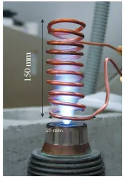
Fig. 3 Induction coil and oxy-combustion flame with methane.
Fig. 4 Experimental circuit of SIT inverter power supply.
is made of brass, and has a diameter of 5.0 mm. An air-cooling fin is attached at the side of this burner to pre-vent overheating. The methane load is 1.8 kW-LHV, and
the equivalent ratio is 1.0. (In other words, the gas flow rate of the methane is 3.0 sLPM, and that of the oxygen is 6.0 sLPM.)
capacitor bank is 4.0 nF. We turned the drive frequency of the SIT power supply to have a maximum coil current at the series resonance of the induction coil circuit. The range of the drive frequency of the SIT power supply is from 0.5 MHz to 1.5 MHz. The induction coil has 14 turns, and is made of 1/8 inch copper tubing that is 20 mm in diame-ter. Cooling water is fed through the copper tube to prevent melting of the coil. The typical duration of RF power input to the flame is 80 msec.
To observe the effect of RF power input on the flame, we conducted spectroscopic measurements using an ICCD camera with a band-pass filter and measured the loading impedance.
In the spectroscopic measurements, we use an ICCD camera capable of 4,500 fps. The time evolution of the emission intensities from OH radicals (λ = 307.2 ± 12.5 nm) was observed.
In loading impedance measurements, the primary cir-cuit’s voltagevrf1, currentirf1, and secondary circuit current
irf2were measured. The loading impedanceZis calculated
from the following formula:
Z= Prf1 I2
rf2
, (1)
Prf1=
1
T
T
0
vrf1(t)·irf1(t)dt, (2)
Irf2 =
1
T
T
0
irf2(t)dt. (3)
We assumed the impedance transformer is an ideal one.
3. Experimental Results and
Discus-sions
3.1
Spectroscopic measurements
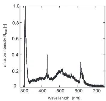
We investigated the influence on the RF power in-put by using spectroscopic measurement with ICCD cam-era. We conducted optical spectroscopic measurement of the oxy-combustion flame with methane (from 300 nm to 800 nm, resolution of this device is 1.0 nm). Figure 5 shows the emission spectrum. The value of the vertical axisI/IMAX is normalized by dividing the intensityI by
the maximum intensityIMAX. The continuous spectrum of
Fig. 5 Emission spectrum of oxy-combustion flame with methane.
Fig. 6 Two-dimensional distribution of the emission intensity of OH radicals obtained using an ICCD camera and mea-surement position effect on the time evolution of emission intensity.
soot is small. This oxy-combustion has a blue flame due to premixed combustion. Thus, we confirmed that the gener-ation of soot is not observed in this flame.
Fig. 7 Two-dimensional distribution of the emission intensity of CH radicals obtained using an ICCD camera and mea-surement position on the time evolution of emission in-tensity.
Fig. 8 Time variations of the emission intensity for OH radicals at P1, P2 and P3 specified in Fig. 6 (λ=307.2±12.5 nm).
(R2) [13, 14].
CH+O2=OH∗+CO (R1)
OH∗A2Σ+→OH∗X2Π
C2+OH=CH∗+CO (R2)
CH∗A2Δ→CH∗X2Π
The emission intensity of OH radical depends on [CH] and the emission intensity of CH radicals is [C2], [OH].
The increase in the emission of OH radical represents an increase in [CH], The increase in the emission of CH rad-icals represents an increase in [C2]. From Fig. 8, [C2] did
not increase with RF power input. We think that soot does not increase with RF power input. [CH] promotes the com-bustion reaction. In this spectroscopic measurement, we observed an increase in the emission intensity from OH radicals in the flame indicating improved combustibility.
This improvement is not obvious, so, further exami-nation is needed to clarify it. If the combustibility is
im-Fig. 9 Time variations of the emission intensity for CH radicals at P1, P2 and P3 specified in Fig. 7 (λ=430.1±10 nm).
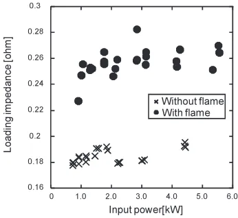
Fig. 10 Dependence of the loading impedanceZon input power Prf1with and without the flame.
proved by RF power input, non-equilibrium plasma might be generated.
3.2
Measurement of the loading impedance
Fig. 11 Input power dependence of flame input powerPflame.
Fig. 12 Numerical model of ICP model.
region.
Figure 11 shows the flame input powerPflamewhich is
calculated from the following expression.
Pflame=
Zw/flame−Zw/o flame
Zw/flame ·
Prf2. (4)
It became clear that the flame input powerPflame
in-creased linearly against the input power, and showed max-imum absorption at 1.5 kW. The flow rate of methane is 3.0 sLPM, and the methane load is 1.8 kW-LHV. We
con-firmed that the flame input power and methane load are approximately the same. We could not visually confirm the effect on the flow of combustion gases, and Fig. 10, shows that the oxy-combustion flame could not absorb all the flame input power, because we do not get synchroniza-tion with the combussynchroniza-tion flame in this device. In our future work, we have to develop a method that can absorb RF power into a combustion flame.
3.3
Estimation of the electron conductivity
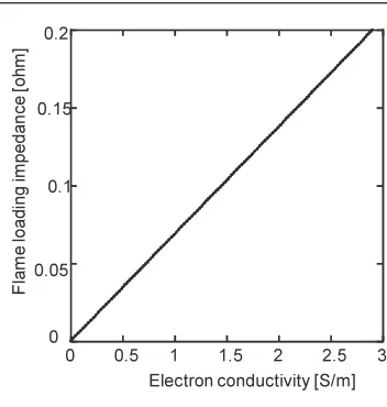
To observe the influence of RF power input, we es-timated the electron conductivity of the oxy-combustion flame by the ICP (Inductively Coupled Plasma) model shown in Fig. 12. Here, p is the plasma radius, sis the radius of the current sheet, and jis the current density of the plasma sheet surrounding the plasma. We use the
fol-Fig. 13 Estimation of the electron conductivity of oxy-combustion using the ICP model.
lowing basic equations (Maxwell’s equations).
∇ ·E=0, (5)
∇ ×E=−∂B
∂t, (6)
∇ ·B=0, (7)
∇ ×B=J+∂D
∂t . (8)
We assume the following boundary conditions. (1) The induction coil has infinite length in thezdirection. (2) The coil current in theθdirection is uniform.
(3) Plasma conductivity is uniform in thezdirection. (4) The electric field has only theθdirection component. (5) The electron conductivity of the flame is uniformly dis-tributed.
(6) The RF input power of the flame is all inductively. The boundary conditions and assumptions are ex-pressed in the following formulas.
Bzp−Bvz=0 (r=p), (9)
Bvz−Bwz =μ0j# (r=s), (10)
Eθp=Evθ (r=p), (11)
Evθ=Eθw (r=s), (12)
B=(Br,Bθ,Bz)=(0,0,B
ze iwt),
(13)
E=(Er,Eθ,Ez)=(0,E
θeiwt,0), (14)
σ(r) =σ=const. (15)
Eis the electric field, Bis the magnetic flux density,
Dis the electric flux density, jis the current density, and μ0is the permittivity.
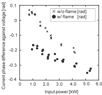
Fig. 14 Input power dependence of current phase difference against voltage.
Fig. 15 Conceptual drawing of the discharge form.
measured the electron conductivity of the oxy-combustion flame by a double probe method [15], which showed that the conductivity of the oxy-combustion flame is approxi-mately 10−4S/m. This result differs greatly from the cal-culated result. In the ICP model, we examined some as-sumptions. In the double probe method, we directly mea-sured the conductivity of the oxy-combustion flame. We considered the difference in the results in terms of the cur-rent phase difference against voltage, which is shown in Fig. 14. From the current phase difference against voltage, we can consider the discharge form of the oxy-combustion with RF power input because it expresses the difference in the coil reactance. Figure 15 shows a conceptual draw-ing of the discharge form. If the current phase is delayed against voltage phase, the discharge form is capacitive dis-charge. If the current phase gains against voltage phase, the discharge form is inductive discharge. From Fig. 14, it is seen that the discharge is dominantly capacitive. The cal-culation of the electron conductivity of oxy-combustion is higher than that of the experimental results using the dou-ble probe method because we assumed that the dominant discharge form is inductive discharge. Inductive discharge is preferable in terms of realizing our proposed method.
We need to consider a more effective discharge method than the usual one.
We need to develop other methods of probe measure-ment, etc., to confirm the generations of non-equilibrium plasma in the future. The RF induction current depends on the frequency. The higher the frequency is, the more the RF induction current grows. A higher frequency device is needed to absorb the RF power.
4. Conclusion
We proposed a new control method of oxy-combustion by using plasma-assisted oxy-combustion to apply oxy-combustion to industrial power plants. We confirmed whether the combustion flame was able to absorb the RF induction power through the induction coil. We conducted spectroscopic measurements to confirm the generation of non-equilibrium plasma. The following knowledge was obtained from this study.
• In the experiment examining the effect of the RF in-duction power on the flame through the coil (d =
20 mm), we confirmed that the loading impedance was increased by RF induction power from the low in-put power region. The absorption of the RF induction power by the combustion flame was thus confirmed. • From spectroscopic measurement of OH and CH
rad-icals, we confirmed an increase in the emission in-tensity of OH radicals. That the possibility that non-equilibrium plasma is generated is thought to be high because of the improved combustibility.
• In the estimation of electron conductivity of oxy-combustion using an ICP model and the results of current phase measurements, the calculated electron conductivity of oxy-combustion is higher than exper-imental results using a double probe method. Capaci-tive discharge is clearly dominant.
[1] S.V. Naik, Combust. Flame134, 425 (2003).
[2] V.R. Malghan, Energy Convers. Manege.37, 569 (1996). [3] Y.Q. Huet al., Energy Convers. Manage.44, 2331 (2003). [4] D. Poirieret al., IFRF Combustion Journal No200404, 1
(2004).
[5] Y.Q. Huet al., Fuel79, 1925 (2000).
[6] A. Beltrameet al., Combust. Flame124, 295 (2001). [7] H.F. Calcote, Combust. Flame1, 385 (1957). [8] T. Pendersenet al., Combust. Flame94, 433 (1993). [9] A.N. Hayhurstet al., Combust. Flame31, 37 (1978). [10] C.S. Maclatchy, Combust. Flame36, 171 (1979). [11] J.M. Goodingset al., Combust. Flame36, 27 (1979). [12] R.M. Clementset al., J. appl. phys.40, 4553 (1969). [13] B.H. Higginset al., Fuel80, 67 (2001).