[Thakur * et al., 5(1): January, 2018]
ISSN: 2349-5197
Impact Factor: 3.765
I
NTERNATIONAL
J
OURNAL OF
R
ESEARCH
S
CIENCE &
M
ANAGEMENT
NUMERICAL SIMULATION OF FATIGUE LIFE ESTIMATION & TENSILE
STRENGTH ANALYSIS OF SIMILAR AND DISSIMILAR MATERIAL OF
WELDED BUTT JOINT
Sultan Singh Thakur* & Prof. Ashutosh Diwedi
*(PG Student VITS Satna MP)
(HOD Mech. Engg. Dept. VITS Satna MP)
DOI: 10.5281/zenodo.1163141
Keywords
:
FEA (Finite element analysis),S-N (Stress-Life Approach), FDM (Finite Difference Method ).Abstract
In this research work welding simulation was carries out in the FEA software to predict Fatigue life cycle and tensile strength in the joining of similar and dissimilar materials. The numerical simulations show that the concentration of stress is maximum near to the joint and at the corner where the cross section has suddenly changed. In order to find out the most optimum setting of material initially three different materials S40C, STS 304 and STS 316L [1] has selected for analysis. Fatigue analysis is performed to predict or estimate the life of weld joint. The test specimen first modeled in the geometry workbench and meshed by proper node and element then it tested under the given boundary condition by applying the tensile loading on one end while other end is fixed. Current project work consists of nine different welds joint with different combination of similar and dissimilar material and analysed with same boundary condition. A comparative study on the basis of stress and life is performing for all the combination of similar and dissimilar material and corresponding curve has plotted. The final selection of material is done by applying the stress life approach in finite element workbench. The result of numerical simulation in form of amount of stress for a butt welded joint is validated by the experimental result of V M Bansode [3].
Introduction
Welding is the process of joining together two pieces of metal so that bonding takes place at their original boundary surfaces. When two parts to be joined are melted together, heat or pressure or both is applied and with or without added metal for formation of metallic bond.
Need for Welding
[Thakur * et al., 5(1): January, 2018]
ISSN: 2349-5197
Impact Factor: 3.765
I
NTERNATIONAL
J
OURNAL OF
R
ESEARCH
S
CIENCE &
M
ANAGEMENT
Fig. 1 Layout of welding process
Problem Formulation
The present study deals with finite element analysis of welded butt joint of 4 mm plate under the tensile loading of 4 KN of dissimilar metal of STS 304, S40C and STS 316L. In this research work welding strength of material and its life cycle of different configuration of material is calculated y using FEA technique. In order to find out the behavior of material property under the different loading condition a design of experiment has also perform to analys the distribution of stress , deflection and cyclic life of weld joint.
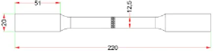
Fig. 2 Schematic representation of welded joint
The length of both plates is taken as 110 mm and the width of the plate is taken as 20 and 12.5 mm in outer and inner side of the plate. The thickness of the plate is 4 mm and the both the plate has join by using butt weld with 35 ° angle.
Assumptions
The following assumptions are made in the present work:
1. Welding joint is properly made according to the ASTM E647 standard and BS 7608 standard. 2. There are no any welding defects present in the specimen.
3. The effect of temperature is negligible during the analysis. 4. Load gradually applied to the joint with respect to the time.
Methodology
The major concern of this project is to use ANSYS to explore and optimize the different features and functions of the design. To achieve this task, transition between workbenches inside the mechanical design section was assured to attain the most feasible shape. The front and top view of the butt joint of weld plate has been shown in Fig. below.
[Thakur * et al., 5(1): January, 2018]
ISSN: 2349-5197
Impact Factor: 3.765
I
NTERNATIONAL
J
OURNAL OF
R
ESEARCH
S
CIENCE &
M
ANAGEMENT
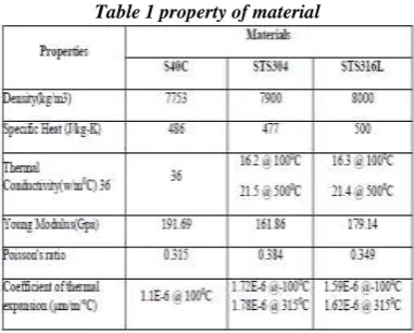
Property of materialMany engineering systems consist of more than one material. Property of materials can be defined either for a group of elements or each individual element, if needed. For different phenomena to be simulated, different sets of material properties are required.
Table 1 property of material
Boundary, Initial and Loading Conditions
Boundary, initial and loading conditions play a decisive role in solving the simulation. Inputting these conditions is usually done easily using commercial pre-processors, and it is often interfaced with graphics. Users can specify these conditions either to the geometrical identities (points, lines or curves, surfaces, and solids) or to the elements or grids. Again, to accurately simulate these Conditions for actual engineering systems requires experience, knowledge and proper engineering judgments. The boundary, initial and loading conditions are different from problem to problem.
Methodology of Static Structural Analysis
Geometry of weld plate
The model shown in Fig. below is being used to analyse the tensile test of butt joint of plate in the following stages.
Fig.4 Butt welded specimen (CAD Model)
Element type and Meshing
[Thakur * et al., 5(1): January, 2018]
ISSN: 2349-5197
Impact Factor: 3.765
I
NTERNATIONAL
J
OURNAL OF
R
ESEARCH
S
CIENCE &
M
ANAGEMENT
Fig. 5 Meshing of Butt Welded Specimen
Result and Discussion
On applying the relevant boundary conditions in the form of load and constraints we achieve the stress zones as shown in Fig. 6 below.
Fig. 6 Stress Distribution in Butt Welded Specimen
This is the major phase of the FEA, and here the solution of the object is achieved in the form of Max Von Mises Stress and Deflection. The stress distribution and the magnitude have been shown in Fig. 4.10 initially the welding tensile test is applied on the mild steel to validate the result of stress and deflection with the VINOD M. BANSODE [3].
Fig. 7 Deflection Plot for Butt Welded Specimen
Validation of Solution with experimental result of Vinod M Bansode
[Thakur * et al., 5(1): January, 2018]
ISSN: 2349-5197
Impact Factor: 3.765
I
NTERNATIONAL
J
OURNAL OF
R
ESEARCH
S
CIENCE &
M
ANAGEMENT
FEA of alternate materialIn order to study the behaviour of different material under the tensile loading condition, a finite element analysis has done for different combination of mild steel material S40C, STS 304 & STS 316L. Here we consider two plates A and B is joining by adding the filler material which is assigned as material C, so there is three different material and three different combination of plate. Finally there is nine different combination of material with plate assignment for FEA study.
Result & Discussion
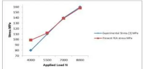
Validation of FEA result with Experimental method [3] of mild steel butt welded plate
stress is being calculated for the butt welded plate under tensile loading at various loading condition. The specimen is tested for different loading values at 4 kN, 5.5kN, 7kN and 8 kN corresponding induced stress are calculated.
Difference between Present Studies with Experimental Analysis
S No Load N
Experimental Stress [3]
MPa
Present FEA stress MPa
Difference % Difference
1 4000 80 99 19 19.2
2 5500 110 112 2 1.8
3 7000 140 139 -1 -0.7
4 8000 160 158 -2 -1.3
The difference in stress value is obtained due to several factors as different grade of mild steel selected for testing and environmental condition and human error also. The difference is minor in experiment No. 2, 3 and 4. But in case of first analysis it shows 19 % difference which is larger than compare to all other analysis.
Stress Computations from the similar and dissimilar material of butt weld joint by FEA
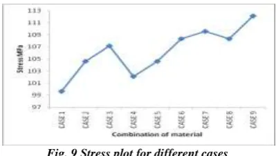
The stress is being calculated for all the nine configuration of material combination of S40C, STS 304 and STS 316L model. The distribution of stress is given in form of curve plot in Fig. 2. the minimum stresses generated by case 1 which is configuration of similar material of S40C on the other hand the maximum value of stresses is found in the case 9 which is obtained by STS 304 and STS 316L material.
Fig. 9 Stress plot for different cases
Deflection Computations from the similar and dissimilar material of butt weld joint by FEA:
[Thakur * et al., 5(1): January, 2018]
ISSN: 2349-5197
Impact Factor: 3.765
I
NTERNATIONAL
J
OURNAL OF
R
ESEARCH
S
CIENCE &
M
ANAGEMENT
Fig. 10 Deflection plot for all cases
Fatigue life Computations from the similar and dissimilar material of butt weld joint by FEA
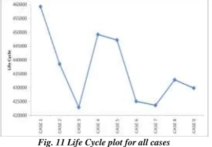
With reference to Table No. 4.5, the fatigue life cycle is being calculated for all the nine configuration of material combination of S40C, STS 304 and STS 316L model. The distribution of life cycle is given in form of curve plot in Fig. 5.3.
Fig. 11 Life Cycle plot for all cases
By the observation of the graph we found that the maximum life cycle of weld joint in the case 1 while the minimum life of weld joint is found in the case 3.with reference to the table No. 4.5 the amount of maximum life cycle is 459250 while the minimum value of life cycle is 422840.
S-N Curve of butt Weld Joint
[Thakur * et al., 5(1): January, 2018]
ISSN: 2349-5197
Impact Factor: 3.765
I
NTERNATIONAL
J
OURNAL OF
R
ESEARCH
S
CIENCE &
M
ANAGEMENT
Fig. 12 S-N Curve plot for all cases
Conclusion
The important conclusion is summaries as:
The material S40C having good tensile strength and exhibit good working life under tensile loading condition.
The similar material configuration of STS 304 and STS 316L show almost similar property under tensile loading condition. The amount of stress and deflection is extremely near in both cases.
The configuration of dissimilar material for all material is exhibit high stress and less life as compare to similar material configuration in all cases.
It is also concluded that weld joint survive for 10e+7 cycles even though the fatigue loading was increased by 4 times.
Finally it is concluded that the design is strong enough to sustain 10e7 cycles for tensile loading conditions. The failure cause can be stated as the wrong grade of weld material, improper welding process, occurrences of multiple cracks, overloading, improper surface preparation, too much corrosive environment variables may have amplified the stress intensity by 5 times to 10 times. At this amplified stress intensity weld component has failed to survive 10e7 cycles.
References
[1] Ranjit Shrestha et al,. “Numerical Simulation of Similar and Dissimilar Materials Welding Process; Quantifications of Temperature, Stress, Strain and Deformation” International Journal of Engineering and Technology, Vol 7 No 1 Feb-Mar 2015.
[2] N.B.Landg et al, “Tensile Strength Analysis of V Groove Butt Weld Joint For Aluminum Alloys Aa 2025 & Aa 7025”, IJARIIE-ISSN(O)-2395-4396, Vol-2 Issue-6 2016.
[3] Vinod M. Bansode et al, “Fatigue Life Estimation of A Butt Welded Joint By S-N Approach”, International Journal of Applied Research in Mechanical Engineering,ISSN: 2231 –5950, Vol-2, Iss-2, 2012.
[4] K. A. Mohammada, et al, “ Experimental Determination of the Fatigue Behavior of Austenitic 316L Stainless Steel under Fatigue and Creep-Fatigue Tests at High Temperature”International Journal of Metal and Steel Research Technology, Vol. 1, No. 1, July 2013, PP: 01- 11.
[5] Shrestha Ranjit et al, “Fatigue Analysis of Dissimilar Materials Welded Specimen Using Finite Element Analysis”, International Journal of Applied Engineering Research ISSN 0973-4562 Volume 11, Number 5 (2016) pp 3390-3393.
[6] Nelson Arzola et al, “Prediction of Fatigue Life for a Transverse Fillet Welded Joint and Analysis of the Influence of Crack Eccentricity on the Failure”. Dyna, year 80, Nro. 182, pp. 95-104. Medellin, December, 2013. ISSN 0012-7353.
[7] Thirugnanam, “Analysis of Stress in Welded Joint in Bending and in Torsion Using Ansys”. Middle-East Journal of Scientific Research ISSN 1990-9233 20 (5): 580-585, 2014.
98 100 102 104 106 108 110 112
459250 422840 447250 423574 429785
Str
e
ss M
Pa
[Thakur * et al., 5(1): January, 2018]
ISSN: 2349-5197
Impact Factor: 3.765
I
NTERNATIONAL
J
OURNAL OF
R
ESEARCH
S
CIENCE &
M
ANAGEMENT
[8] Ahmet H. Ertas And Fazil O. Sonmez “A parametric study on fatigue strength of spot-weld joints” Blackwell Publishing Ltd. Fatigue Fract Engng Mater Struct 31, 766–776, 2008.
[9] Ahmet H. Ertas “Measurement and Assessment of Fatigue Life of Spot-Weld Joints” Journal of Engineering Materials and Technology Jan 2009, Vol. 131 / 011011-1.
[10] T. LASSEN, “A model is investigated where fatigue life and fatigue limit are treated as random variables”Supplement to the Welding Journal, December 2005.
[11] M.N.Chougule et al , “Experimental And Analytical Study of Thermally Induced Residual Stresses For Stainless Steel Grade Using Gmaw Process” 5th International & 26th All India Manufacturing Technology, Design and Research Conference (AIMTDR 2014) December 12th -14th, 2014, IIT Guwahati, Assam, India.
[12] Miodrag Arsic “Experimental examination of fatigue life of welded joint with stress concentration” Frattura ed Integrità Strutturale, 36 (2016) 27-35; DOI: 10.3221/IGF-ESIS.36.03
[13] H. S. Patil,”Experimental study on the effect of welding speed and tool pin profiles on AA6082-O aluminum friction stir welded butt joints”, International Journal of Engineering, Science and Technology Vol. 2, No. 5, 2010, pp. 268-275.
[14] Dr.Ali Sadiq Yasir “Study the Effect of Welding Joint Location on the Fatigue Strength and Fatigue Life for Steel Weldment”, Asian Transactions on Engineering (ATE ISSN: 2221 - 4267) Volume 02 Issue 04.