© Universiti Tun Hussein Onn Malaysia Publisher’s Office
IJIE
Journal homepage: http://penerbit.uthm.edu.my/ojs/index.php/ijie ISSN : 2229-838X e-ISSN : 2600-7916
The International
Journal of
Integrated
Engineering
Parametric Optimization of Robot-based Single Point
Incremental Forming Using Taguchi Method
Nazarul Abidin Ismail
1,2,*, Mohd Idris Shah Ismail
1, Mohamad Aizat Mohd
Radzman
1, Mohd Khairol Anuar Mohd Ariffin
1, Azizan As'arry
11Department of Mechanical and Manufacturing Engineering, Faculty of Engineering, Universiti Putra Malaysia, 43400
UPM Serdang, Selangor, MALAYSIA.
2Industrial Electronic Department, German-Malaysian Institute, Jalan Ilmiah, Taman Universiti, 43000 Kajang, Selangor,
MALAYSIA.
*Corresponding Author
DOI: https://doi.org/10.30880/ijie.2019.11.01.023
Received 07 August 2018; Accepted 13 February 2019; Available online 30 April 2019
1.
Introduction
Recently, the importance of sheet metal forming is rapidly increased due to a customer demand towards more personalized products and the requirement of smaller batches. However, manufacturers have to deliver faster with shortened product design and production phases. The phase of prototyping in the design of a product can take a long time and sometimes it can exceed the budget or, even worse, the products need to be launched before optimizing the design phase, showing the need for rapid prototyping [1]. The increase in popularity of flexible forming techniques has given rise to increase interest in the single point incremental forming (SPIF) process [2]. SPIF is promising technology in rapid manufacturing for medical implants (cranial plate, backseat orthosis) [3-4], transportation (car fender) and aerospace (airfoils) [5-7].
SPIF is a forming process that involves incrementally deforming a sheet into a designed shaped by a tool attached a control unit, usually a CNC machine or an industrial robot, that moves along a designated tool path. Owing to the utilization of CNC machine or industrial robot with a low cost production setup, this method has been proved to be a
*Corresponding author: [email protected]
2019 UTHM Publisher. All right reserved.
Abstract: Sheet metals forming process is widely used in consumer and industrial products. However, the conventional sheet metal forming has low flexibility and product quality. It also prolongs the time-to-market in producing prototype products that required low costs. Single point incremental forming (SPIF) is one of relatively new sheet metal forming process. The increase interest in new techniques for forming processes and the usage of robotics in the industry has created more researches on the SPIF. Robot-based SPIF is a method of deforming a sheet metal to create designed workpieces by utilising a forming tool that attached to an industrial robot. In this present work, an optimization study for combination of process parameters in robot-based single point incremental forming of aluminum alloy sheet was experimentally investigated using Taguchi method to achieve an excellent surface roughness. A number of forming experiments were conducted using the L18 orthogonal array. Analysis of Variance (ANOVA) was used to identify the most significant process parameters affecting the surface roughness. The results analysis indicates that the optimum process parameters for surface roughness are obtained as 0.3 mm of step size, 150 mm/s of robot speed and 45 degree of wall angle. The most significant process parameter is step size and followed by robot speed. The study revealed the surface quality could be improved by proper selection of process parameters.
flexible process [8]. The potential of this process is significant as it allows significant reduction in material usage compared to conventional deep drawing processes as it requires no dies in forming the sheet metal, effectively reducing the number of steps in a manufacturing process. The conventional sheet metal forming processes are depending on tooling, which costs in terms of time and money. Due to these factors along with increasing variants, varieties in the sheet metal fabrication, highly flexible forming process are being developed.
The higher utilisation of robots in the industry has contributed to researchers to investigate the potential utilisation of industrial robots to carry out the SPIF process instead of utilizing a CNC machine. Due to the dynamic working range of industrial robots, the ability of the SPIF process to create a larger and complex workpiece can be enhanced. However, the robot-based SPIF process has yet to be fully optimised and adopted in the industry. But with major companies such as Ford are interested in the prospect of the technology, SPIF has become a topic that researchers are focusing on, in order to develop the process for industry adaptation [7]. This technology also has a great potential to be utilized in Industry 4.0 since it can offer an integration of robot, intelligence-based monitoring and control system with internet-of-things (IoT) devices and networks for cyber-physical systems [9-10].
The SPIF process has multiple factors that contribute to the quality of the final workpiece. Nimbalkar and Nandedkar [11] analyzed the current state of the art of incremental sheet forming by comparison of incremental sheet forming and spinning forming, type of incremental sheet forming, equipment used in the process, tool path generation, material process parameter and deformation mechanism in incremental sheet forming. Vanhove et al. [12] confirmed that the increase in feed rate has a positive effect on ductility and increases the maximum forming angle. Callegari et al. [13] performed several experiments to validate the complex methodology for system design and prototyping. The important parameters are types of materials, number of axes of the task, the kind of interpolation between the points, the path imposed to the tool and the size of punch. Baturone et al. [14] investigated the influence of geometrical parameters on the force in two directions in a SPIF process with three types of component as a dome, a truncated cone and a truncated pyramid.
Tisza [15] defined short historical overview of sheet incremental forming that was originally being study and analyses recently. One of the measures of effectiveness of the process is through analysing the surface roughness of the final part. Mugenderan et. al [16] had attempting to optimize the metal forming parameters such as surface roughness and sheet thickness after forming which is to obtain minimum surface roughness and maximum wall thickness in incremental forming. Cus and Zuperl [17] briefly present a compensation method in milling in order to take into account tool deflection during cutting condition optimization or tool path generation.
With multi-parameters are affecting the process, it is important to analyse the various changes that could occurred within the process when manipulating the process parameters. Therefore, there is a need to find an optimum level of process parameters for the process to be carried out. Conventional experimental design methods are too complex and not easy to use. This study attempts to optimize the settings of the process parameters. Using a simple, effective and systematic approach, the optimal process parameters can be derived. As a powerful and high-quality experimental tool [18-20], Taguchi method uses a special design called orthogonal array to study the entire parameter space with a small number of experiments. In this method, process parameters that influence the processes are separated into two main groups: control factors and noise factors. A statistical analysis of variance (ANOVA) is performed to identify the process parameters that are statistically significant. The optimal combination of the process parameters can then be predicted based on the above analysis.
In this present work, an optimization study for combination of process parameters in robot-based single point incremental forming of aluminum alloy sheet was experimentally investigated to achieve an excellent surface roughness. Experiments were conducted under different process parameters, namely, robot speed, step size and wall angle. The settings of process parameters were determined by using Taguchi experimental design method. In addition, the effect of the process parameters and their significance on the surface roughness is statistically evaluated by using ANOVA.
2.
Methodology
2.1
Materials and Methods
In this study, AA3003 aluminum alloy with 0.5 mm thickness was used as specimen. The forming tool used in the experiments was fabricated from AISI D2 tool steel with a hemi-spherical tip of a 10 mm in diameter. The experimental work was performed using a forming tool, which integrated with a six degree-of-freedom industrial robot as shown in Fig. 1(a). The robot has great flexibility and is suitable for both pint-to-point and continuous-path controlled tasks. The blank holder is fixed vertically on the worktable, and the forming tool is fixed to the fixture attached to the robot. The tool path used was a helical tool path and the experiments has been conducted to produce the shape profile, which is a truncated cone with a diameter of 200 mm and a depth of 30 mm as shown in Fig. 1(b) and 1(c), respectively.
tool along the radius of the truncated cone. For example, a 45-degree wall angle for a 0.3 mm step size is achieved by moving the tool by 0.3 mm along the radius before the tool moves vertically by 0.3 mm.
Since the lubrication in SPIF process is needed to reduce friction between forming tool and formed sheet metal in the forming area, the lubrication of synthetic oil with grade of SAE 15W-40 was used. After the robot-based SPIF process, the specimen was cut for measuring the surface roughness (Ra) at four different measurement locations per specimen
using a Mahr Perthometer S2 tester as shown in Fig. 2, and the average roughness values of surface roughness were evaluated.
Fig. 1 - (a) Experimental setup; (b) helical too path; (c) truncated cone shape of formed specimen
Fig. 2 - (a) Surface roughness measurement setup; (b) four locations for surface roughness measurement
2.2
Design of Experiment
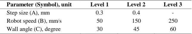
Taguchi method is an excellent technique for design of experiment that can reduces the number of experiments drastically, and subsequently to decrease the experimental time and cost associated with it. In this study, Taguchi method was used to determine an optimal processing parameter for minimizing the surface roughness in robot-based SPIF process. The three process parameters namely step size (A), robot speed (B) and wall angle (C) were used as control factors and each parameter was designed to have three-levels, except the parameter of step size with two-levels as shown in Table 1.
Table 1 – Process parameters and their levels
Parameter (Symbol), unit Level 1 Level 2 Level 3
Step size (A), mm 0.3 0.4 -
Robot speed (B), mm/s 50 150 250
Wall angle (C), degree 30 45 60
𝑆/𝑁 = −10 ∙ 𝑙𝑜𝑔 [1 ∑𝑛 (𝑦 2)] (1)
𝑛 𝑖=1 𝑖
where n is the number of replications, and yi represents the experimental observed value (surface roughness) of the ith
experiment. Each L18 and measurement of surface roughness was made four times at different locations.
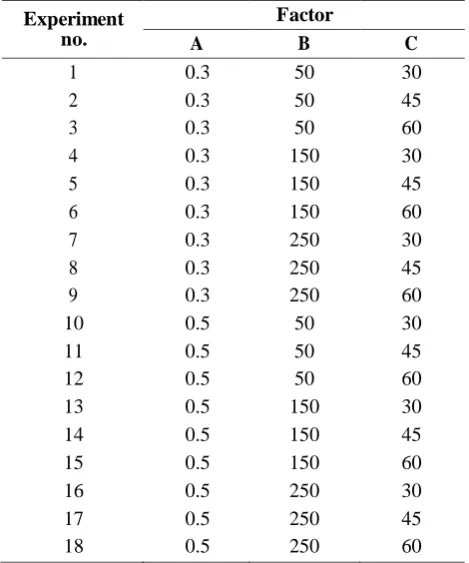
Table 2 – Experimental design using L18 orthogonal array
Experiment no.
Factor
A B C
1 0.3 50 30
2 0.3 50 45
3 0.3 50 60
4 0.3 150 30
5 0.3 150 45
6 0.3 150 60
7 0.3 250 30
8 0.3 250 45
9 0.3 250 60
10 0.5 50 30
11 0.5 50 45
12 0.5 50 60
13 0.5 150 30
14 0.5 150 45
15 0.5 150 60
16 0.5 250 30
17 0.5 250 45
18 0.5 250 60
3.
Results and Discussion
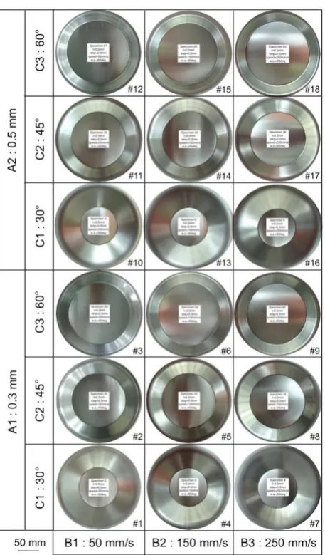
Fig. 3 shows top view of the formed AA3003 aluminum alloy sheet in robot-based SPIF for 18 different combinations of process parameters and the measured values of surface roughness are listed in column two to five of Table 3. It indicates that the surface roughness has no obvious trend with respect to step size, robot speed and wall angle. Further analysis on the measured surface roughness is required to obtain a result that can be interpreted. Thus, the average surface roughness and the S/N ratio were used as presented in column six and seven five of Table 3, respectively.
The results analysis was performed using MINITAB 14 statistical software to find the optimized value and its influence on surface roughness. The S/N ratios were calculated for surface roughness using LB characteristic that expressed in Equation (1). Since the LB characteristic is used in this study, it shows that the S/N ratio increases as the surface roughness decreases and they have an inverse relationship. This reflects that the highest S/N ratio leads to the optimum combination of parameters for obtaining a lowest value of surface roughness (i.e. good product quality).
Table 4 shows the response table of robot-based SPIF for the surface roughness response. The average response characteristics for each level of each factor are presented in the response table. The delta value measures the size of the effect by calculating the difference between the highest and lowest value for each characteristic response. The rank and delta values can assist to evaluate which factors have the greatest effect on the response. It shows that the step size has most influence on the surface roughness and shown as first rank in Table 4.
The main effects plots for S/N ratios illustrate how the process parameters and their level can be affected to the response. The main effects plots also known as the signal response graph for the orthogonal array. Fig. 4 shows the main effects plot for step size, robot speed and wall angle. It indicates that the optimal combination of parameter levels by reading the peak of each graph. Thus, the optimum levels for step size, robot speed and wall angle are 0.3 mm (A1), 150 mm/s (B2) and 45 degree (C2), respectively.
= (
Fig. 3 – Top view of formed AA3003 aluminum alloy sheet in robot-based SPIF (Step size, A; robot speed, B; wall angle, C)
Based on Table 5, it is worth to note that the P-value for parameter of step size (A) is 0.001, which indicates that there is strong evidence that step size influences the surface roughness produced by the robot-based SPIF process. It also shows the influence of robot speed (B), which has a P-value of exactly 0.05. Although it does not have as strong as evidence than step size, it does influence the surface roughness significantly. The only parameter that has no evidence to support its significance on affecting the response is wall angle with P-value of more than 0.05, which is 0.389. The parameter of wall angle has no significant effect to the SPIF process when the material thickness used is equal or more than 0.5 mm [11, 22-23].
Based on the ANOVA that was carried out, the parameter of step size contributes the most to the robot-based SPIF process with a percentage contribution of 45.35%. This supports the previous literatures [24-25] on the SPIF process, whereby the step size increases the accuracy of the final product. Robot speed has less significant compared to step size, as it only contributes to about 19.41% of to the robot-based SPIF process. The wall angle contributes the least with a percentage contribution ratio of only 5.14% and can be ignored due to its weak P-value.In this study, confirmation experiment was carried out to evaluate the performance of experimental trial conducted for surface roughness under optimal condition (step size, A1 = 0.3 mm, robot speed, B2 = 150 mm/s and wall angle, C2 = 45 degree). Initially, the maximum S/N ratio for each control factor is considered to define whether or not the minimum surface finish is acceptable [26]. This maximum S/N ratio could be predicted using Equation (2).
predicted 𝑚
𝑓
𝑖=1 𝑖 𝑚) (2)
where m is the overall mean of S/N ratio (4.751 dB), f is the number of factors, and i represents the mean of S/N ratios
at the optimal level of each factor i. From Table 4, the i for step size (A1), robot speed (B2) and wall angle (C2) are
+ ∑ −
5.806 dB, 5.724 dB and 5.243 dB, respectively. According to these values, the maximum S/N ratio can be predicted as 7.290 dB. Subsequently, the predicted minimum surface roughness is 0.433 μm at optimal condition.
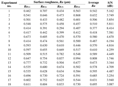
Table 3 –L18 orthogonal array experimental results for surface roughness in robot-based SPIF of aluminum alloy sheet
Experiment no.
Surface roughness, Ra (μm) Average
Ra
S/N (dB)
Ra(1) Ra(2) Ra(3) Ra(4)
1 0.462 0.707 0.434 0.563 0.542 5.162
2 0.541 0.646 0.473 0.868 0.632 3.749
3 0.501 0.433 0.482 0.601 0.506 5.854
4 0.548 0.575 0.458 0.457 0.510 5.811
5 0.414 0.391 0.294 0.407 0.377 8.414
6 0.417 0.442 0.399 0.412 0.418 7.581
7 0.673 0.605 0.470 0.570 0.580 4.670
8 0.414 0.474 0.561 0.500 0.487 6.194
9 0.593 0.630 0.610 0.446 0.570 4.816
10 0.597 0.655 0.669 0.517 0.610 4.259
11 0.509 0.515 0.782 0.548 0.589 4.449
12 0.647 0.754 0.837 0.994 0.808 1.746
13 0.777 0.732 0.504 0.677 0.673 3.344
14 0.535 0.600 0.674 0.502 0.578 4.709
15 0.535 0.628 0.634 0.584 0.595 4.487
16 0.696 0.730 0.724 0.591 0.685 3.254
17 0.602 0.752 0.625 0.544 0.631 3.940
18 0.611 0.604 0.833 0.730 0.695 3.087
Table 4 – Response table for robot-based SPIF of AA3003 aluminum alloy sheet
Level Step size (A)
Robot speed (B)
Wall angle (C)
1 5.806 4.203 4.417
2 3.697 5.724 5.243
3 - 4.327 4.595
Delta 2.108 1.521 0.826
Rank 1 2 3
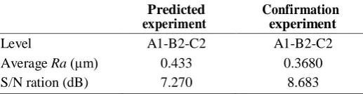
As shown in Table 6, the predicted value was higher than the measured value for the confirmation experiment, indicating the surface roughness is improved. While the S/N ratio has increased for the measured value, showing less noise in the process. The confirmation experiment indicates that the optimization process has produced acceptable results, since there is both improvements in the S/N ratio and the measured average surface roughness that was compared to the predicted value.
Table 5 – Results of ANOVA for surface roughness
Source DF SS MS F-test P-value PCR (%)
A 1 20.003 20.003 18.08 0.001 45.35
B 2 8.562 4.281 3.87 0.050 19.41
C 2 2.266 1.133 1.02 0.389 5.14
Error 12 13.276 1.106 30.10
Total 17 100
Table 6 – Results of confirmation experiment
Predicted experiment
Confirmation experiment
Level A1-B2-C2 A1-B2-C2
Average Ra (μm) 0.433 0.3680
S/N ration (dB) 7.270 8.683
4.
Conclusion
A parametric optimization and effect of step size, robot speed, and wall angle in robot-based SPIF process of aluminum alloy sheet have been experimentally investigated on the average surface roughness to achieve an excellent surface quality. As a result of experimental trials performed using Taguchi orthogonal array and ANOVA, it was found that the optimum level of process parameters to obtain better surface roughness was A1 (step size, 0.3 mm), B2 (robot speed, 150 mm/s), and C2 (wall angle, 45 degree). It reveals that the step size was the most significant factor affecting the surface roughness with a percentage of 45.35%. It followed by the robot speed at 19.41%. Otherwise, the wall angle was not the main affecting parameter and highly negligible when forming the aluminum alloy. Based on the result of confirmation test, it shows that the surface roughness in robot-based SPIF is greatly improved by using this approach. Analysis of material thickness and tool path would be focused in future work to cover the variety of shape and products dimension.
Acknowledgement
The authors would like to acknowledge the Universiti Putra Malaysia (UPM) for financial support under Putra Grant (GP-IPS/2016/9503100).
References
[1] De Backer, K., & Espinoza, J.M. (2005). Development of a business plan for the sheet metal part oriented rapid prototyping market. Master Thesis, KU Leuven.
[2] Behera, A. K., Verbert, J., Lauwers, B., & Duflou, J.R. (2013). Tool path compesation strategies for single point incremental sheet forming using multivariative adaptive regression splines. Computer-Aided Design, 45(3), 575- 590.
[3] Duflou, J.R., Behera, A.K., Vanhove, H., & Bertol, L.S. (2013). Manufacture of accurate titanium cranio-facial implants with high forming angle using single point incremental forming. Key Engineering Materials, 549, 223- 230.
[4] Bagudanch, I., Lozano-Sanchez, L.M., Puigpinos, L., Sabater, M., Elizalde, L.E., Elias-Zuniga, A., & Garcia- Romeu, M.L. (2015). Manufacturing of polymeric biocompatible cranial geometry by single point incremental forming. Procedia Engineering, 132, 267-273.
[5] Bambach, M., Taleb Araghi, B., & Hirt, G. (2009). Strategies to improve the geometric accuracy in asymmetric single point incremental forming. Production Engineering, 3(2), 145-156.
[7] Behera, A. K., De Sousa, R. A., Ingarao, G., & Oleksik, V. (2017). Single point incremental forming: An assessment of the progress and technology trends from 2005 to 2015. Journal of Manufacturing Processes, 27, 37-62.
[8] Khare, U., & Pandagale, M. (2014). A review of fundamentals and advancement in incremental sheet metal forming. IOSR Journal of Mechanical and Civil Engineering, 8, 42-46.
[9] Paniti, I. (2014). Adaptation of incremental sheet forming into cloud manufacturing. CIRP Journal of Manufacturing Science and Technology, 7, 185-190.
[10] Sa de Farias, J.B., Marabuto, S., Martins, M.A.B.E., Ferreira J.A.F., Campos, A.A., & Alves de Sousa, R.J. (2014). Towards smart manufacturing techniques using incremental sheet forming, In Evon A.T. (Eds). Smart Manufacturing Innovation and Transformation: Interconnection and Intelligence, 159-189.
[11] Nimbalkar, D.H., & Nandedkar, V.M. (2013). Review of incremental forming of sheet metal components. International Journal of Engineering Research and Applications, 3(5), 39-51.
[12] Vanhove, H., Mohammadi, A., Guo, Y.S., & Duflou, J.R. (2014). High-speed single point incremental forming of an automotive aluminium alloy. Key Engineering Materials, 622, pp. 433-439.
[13] Callegari, M., Amodio, D., Ceretti, E., & Diardini, C. (2006). Sheet incremental forming: Advantages of robotised versus CNC machines. In Low K.H. (Eds) Industrial Robotics, Programming, Simulation and Application, Intech, 493-514.
[14] Baturone, I., Moreno-Velo, F.J., Blanco, V., & Ferruz, J. (2008). Design of embedded DSP-based fuzzy controllers for autonomous mobile robots. IEEE Transactions on Industrial Electronics, 55(2), 928-936.
[15] Tisza, M. (2012). General overview of sheet incremental forming. Journal of Achievements in Materials and Manufacturing Engineering, 55(1), 113-120.
[16] Mugendiran, V., Gnanavelbabu, A., & Ramadoss, R. (2014). Parameter optimization for surface roughness and wall thickness on AA5052 aluminium alloy by incremental forming using response surface methodology. Procedia Engineering, 97, 1991-2000.
[17] Cus, F., & Zuperl, U. (2011). Real-time cutting tool condition monitoring in milling. Journal of Mechanical Engineering, 57(2), 142-150.
[18] Khalid, S.N.A., Ismail, A.E., Zainulabidin, M.H., Ariffin, A.M.T., Hassan, M.F., Ibrahim, M.R., & Rahim, M.Z. (2018). Mechanical properties of twill kenaf woven fiber reinforced polyester composites. International Journal of Integrated Engineering, 10(4), 49-59.
[19] Narong, O.L.C., Sia, C.K., Yee, S.K., Ong, P., Zainudin, A., Nor, N.H.M., & Hassan, M.F. (2018). Optimization of EMI shielding effectiveness plaster mortar containing POFA using Taguchi design and Flower Pollination algorithm method. International Journal of Integrated Engineering, 10(3), 93-101.
[20] Ibrahim, M.H.I., Muhamad, N., Sulong, A.B., Jamaludin, K.R., Ahmad, S., & Nor, N.H.M. (2010). Single performance optimization of micro metal injection molding for the highest green strength by using Taguchi method. International Journal of Integrated Engineering, 2(1), 35-44.
[21] Gelman, A. (2013). P-values and statistical practice. Epidemiology, 24(1), 62-73.
[22] Oleksik, V. (2014). Influence of geometrical parameters, wall angle and part shape on thickness reduction of single point incremental forming. Procedia Engineering, 81, 2280-2285.
[23] Pathak, P. (2017). A brief review of incremental sheet metal forming. International Journal of Latest Engineering and Management Research, 2(3), 35-43.
[24] Gatea, S., Ou, H., & McCartney, G. (2016). Review on the influence of process parameters in incremental sheet forming. International Journal of Advanced Manufacturing Technology, 87(1-4), 479-499.
[25] Bhattacharya, A., Maneesh, K., Venkata Reddy, N., & Cao, J. (2011). Formability and surface finish studies in single point incremental forming. Journal of Manufacturing Science and Engineering, 133(6), 061020 (8 pages). [26] Ribeiro, J., Lopes, H., Queijo, L., & Figueiredo, D. (2017). Optimization of cutting parameters to minimize the