Journal of Engineering Sciences, Volume 6, Issue 2 (2019), pp. E 41–E 46 E 41 JOURNAL OF ENGINEERING SCIENCES
ЖУРНАЛ ІНЖЕНЕРНИХ НАУК
ЖУРНАЛ ИНЖЕНЕРНЫХ НАУК
Web site: http://jes.sumdu.edu.ua DOI: 10.21272/jes.2019.6(2).e7 Volume 6, Issue 2 (2019)
Airplane Waste Disposal System Tank Designing Using Numerical Simulation
and Experimental Bench Results
Medvediev S. V.1*, Lantin D. H.2
1 ANTONOV State Enterprise, 1 Academic Tupolev St., 03062 Kyiv, Ukraine;
2 United Interiors International, LLC, 2535 Seabrook Island Rd., Johns Island, SC 29455, USA
Article info: Paper received:
The final version of the paper received: Paper accepted online:
March 22, 2019 December 7, 2019 December 12, 2019
*Corresponding Author’s Address:
[email protected]
Abstract. Modern passenger aircraft cannot be considered without the requirements to ensure the safety and comfort of passengers on board. One of the systems that provide the necessary comfort on the plane is the waste disposal system, which is designed to meet the physiological needs of the human body. Today, a promising waste disposal system type is a vacuum principle of operation. The vacuum-type waste disposal system is a combination of complex multifunctional subsystems: waste collection, waste storage, vacuumization, drain and flush, system control. Such systems development, consisting of devices, based on heterogeneous physical principles of operation, is a complex scientific and technical problem associated with the conduct of diverse applied research in the field of design, development and targeted use of the system. One main system element is a waste storage tank. An important step in the tank design is to determine its weight and size characteristics in the early stages of development. These characteristics are significantly influenced by the tank filling process, which also determines the placement of equipment in it. The aim of the work presented in the article is to study the tank filling process with the help of numerical simulation methods.
Keywords: vacuum, waste tank, design, experimental bench.
1
Introduction
Modern design (creation) of any system onboard an aircraft is a complex, multifactor, branch task to finding the optimal ratio of parameters [1], in which the main criteria are the safety and passengers’ comfort on board.
One of the systems providing the necessary comfortable conditions on board the aircraft is a waste disposal system, which is designed to meet the physiological needs of the human body.
Today, a promising type of waste disposal system is a vacuum principle of operation, in which one of the main elements of the system is a waste storage tank. An important step in the design of the system and the waste storage tank is the determination of its characteristics in the early design stages.
2
Literature Review
The development of vacuum systems on civil aviation aircraft began its history from the mid-70s of the twentieth century. So, in 1975, inventor James Kemper patented a vacuum waste disposal system, the principle which is used today on modern passenger aircraft.
The vacuum toilet was first installed on Boeing aircraft in 1982.
From now on the vacuum waste removal system becomes popular and promising on airplanes. Improvements and development of new equipment for vacuum systems lead to the creation of more advanced systems, such as the “Revolutionary” vacuum toilet by Zodiac Water and Waste Aero Systems. Further development of vacuum waste removal systems is used not only on aircraft but also in the entire transport industry.
In the CIS, the Research Institute of Standardization and Unification (RISU) was engaged in vacuum waste disposal systems. Research and development of a vacuum-type waste disposal system were carried out for the Tu-334 aircraft.
A simplified aircraft vacuum waste disposal system diagram is shown in Figure 1. The main elements of the system are waste receptacle (toilet bowl unit) 1, waste disposal pipeline 2, waste storage tank 3 (with waste braking device installed at the inlet and dehumidification device at the tank outlet), vacuumization subsystem (vacuum generator 5, vacuum pipelines 4).
E 42 MECHANICAL ENGINEERING: Computational Mechanics waste storage tank and the passenger cabin, the waste
from receiver 1 through waste disposal pipe 2 is moved to tank 3, where it should be stored until the end of the flight. On the ground, the air pressure drop is created by a vacuum pump (vacuum generator). The flight uses a natural air pressure drop between the atmosphere and the passenger cabin.
Figure 1– Design scheme of an aircraft vacuum system
The waste storage tank is one of the key system elements [2, 3]. When designing the tank and determining its required volume, you must perform:
– determine the maximum amount of waste to be stored in the tank;
– determine the device configuration of waste braking when it enters the tank;
– determine the configuration of the dehumidification device;
– explore the process of filling the tank with waste (gas-dynamic calculation);
– perform a strength calculation of the tank and the whole system.
One of the important requirements that arise when developing a waste disposal system is the tightness requirement. The system tightness is caused not only by the tightness of the pipeline joints network but also by the requirement to preserve the waste in the tank without further movement through the vacuumization subsystem. If the developed system design does not comply with this requirement, the following negative consequences may occur:
– formation of significant ice formations on the aircraft outer surface at the exit point of the vacuumization pipelines, which, after detachment, may damage the aircraft structure;
– vacuum generator breakdown;
– entering the waste on the airfield during a stop leads to the imposition of significant fines by the airport authority.
Despite recent research in this area, some aspects of system development have not been fully resolved. The development of methods for calculating the main characteristics of the waste tank basically remains the prerogative of aircraft manufacturers and firms
developing specialized equipment for aircraft and was not published in the open press.
The information presented in the literature regarding methods for calculating vacuum systems [4–14] does not allow one to determine the necessary characteristics of the system and the waste tank. In this regard, the development of methods for designing and calculating the waste disposal system, as well as its individual elements, particularly, the waste storage tank is an important task.
At the stage of research work, when conducting full-scale tests is extremely difficult and requires significant costs, the actual task is to determine the volume of the tank, which is necessary for storing a given amount of waste, as well as its configuration taking into account the zonal equipment distribution in the aircraft compartments. The required tank volume largely depends on the filling process, the study of which is presented below.
3
Research Methodology
3.1
Waste storage tank filling processes
investigation using numerical modeling
In the study of the tank filling process using numerical simulation methods [15–19], ANSYS CFX software was used.
The object of the study is a waste storage tank designed for the An-148-100 passenger aircraft. The appearance of the tank is shown in Figure 2.
Initial data:
– maximum tank diameter dmax = 521 mm; – tank length L = 828 mm;
– pressure in the tank after turning off the vacuum generator Ptank = 0.51531 kgf / cm2;
– cabin pressure Pcab = 1.03·105 Pa.
The three-dimensional model of the tank is made using the software NX 8.5.
Figure 2 – Antonov-148-100 aircraft waste storage tank model
Journal of Engineering Sciences, Volume 6, Issue 2 (2019), pp. E 41–E 46 E 43 7 mm, with a tank volume of 140 l and input/output
diameter 50 mm, respectively. The number of design elements was 5.5 million.
A two-phase air-water medium separated by a free surface is considered. The air is presented as an ideal gas SST turbulence model.
Figure 3 – Calculated waste tank mesh
The flow was modeled in a non-stationary setting (Transient). The simulation time of the tank filling process is about 1.0 s and includes the following stages of the system unit’s operation: the vacuum generator starts, the waste receiver flap opening, the ingress of a portion of water into the tank, the flap closing.
At the initial moment of time in the tank, there is a certain water level, the height of the column of which is equal to yh (Figure 4).
The initial values of the velocity vector are 0 m/s. The initial pressure value is set by the Pref functions, which
are determined by the function:
where Pin = 1.03·105 Pa – air pressure; Pw – water pressure determined using the following function:
Figure 4 – Tank water level at the initial time
The initial temperature of both phases is t = 22 ° C. The volume coefficient content of each phase in the computational domain is determined through the function WVF:
The first studies showed that the stability of the calculation is ensured with a time step of 1.0 ms or less.
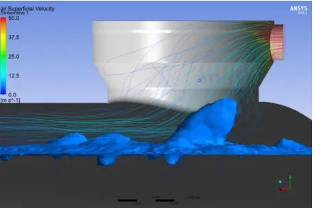
Visualization of vacuum creating process in a tank at a height of waste level yh = 400 mm shown in Figures 5–8.
Investigation of the creating vacuum process revealed that separation of particles of water (waste) is due to the high air velocity in the gap between the free surface and the tank housing.
E 44 MECHANICAL ENGINEERING: Computational Mechanics
Figure 7 – The beginning of separation formation Figure 8 – The moment after vacuum generator turning off When reducing the cross-sectional area of this gap,
associated with an increase in the level of waste in the tank, the separation process occurs with greater intensity.
The results of the numerical tank filling process simulation made it possible to determine the dependence of the volumetric water content coefficient in the outlet pipeline on various values of the initial water level in the tank. The results of the calculations are presented in Table 1.
Table 1 –The result of a numerical study of the filling process
yh, mm Water volume fraction
500 0.009
450 0.018
400 0.002
371 0.004
350 1.052·10–5
300 3.880·10–7
Figure 9 shows the volumetric content of water that enters the pipelines of the vacuumization subsystem depending on the thickness of the air gap above the water.
Figure 9 – Percentage of water fraction from the change in the height of the water column
3.2
The hydraulic processes research
experimental bench of filling the waste
storage tank
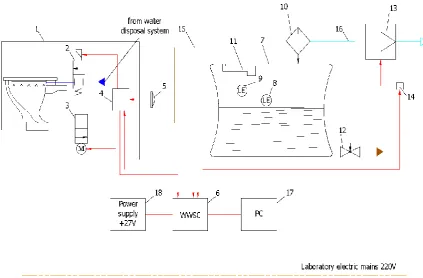
For carrying out field tests, a functional stand was developed, for which a special waste tank was designed.
A stand schematic diagram is shown in Figure 10. The stand consists of the following units:
1 – waste receptacle; 2 – splitter valve; 3 – damper;
4 – valve control unit; 5 – flush button;
6 – system management controller; 7 – waste storage tank;
8 – tank level sensor ¾''; 9 – sensor level 100 % tank; 10 – separator;
11 – waste dispenser; 12 – waste discharge valve; 13 – vacuum generator;
14 – starting relay of vacuum generator; 15 – waste disposal pipeline;
16 – vacuum pipe (the material is plexiglass); 17 – personal computer;
18 – power supply.
An experimental tank 7 is made based on a regular tank and has differences in terms of the presence of built-in observation wbuilt-indows, to ensure control and monitorbuilt-ing of the experiment process. The vacuum system pipe 16, which connects the tank with the vacuum generator, is made of transparent Plexiglas for visual observation.
For the tests, an experiment plan was developed, allowing a comprehensive assessment of the tank’s capabilities and its characteristics in terms of filling, assessment of sensor placement and tank spray nozzles, waste diverter efficiency, complete removal (draining) of waste from the tank. The tests were carried out in two stages: at the first stage, the testing of filling processes was carried out with the help of a working medium - water. In the second stage, the tests were carried out with the help of a working environment – a waste simulator.
Journal of Engineering Sciences, Volume 6, Issue 2 (2019), pp. E 41–E 46 E 45 Figure 10 – Experimental bench schematic diagram
4
Results and Discussion
According to the results of numerical simulation (Figure 9), the maximum level of waste at which the separation of the fraction from the surface begins to occur is yh = 371 mm (which corresponds to an air gap height of 150 mm).
These numerical results are used to calculate the required tank volume.
The test results carried out on the stand showed that up to the height of the air gap of about 150 mm and more visual signs of water ingress, waste and their traces on the walls of the vacuum system pipeline are not observed.
5
Conclusions
The compiled computational model of the filling processes the waste storage tank using the software Ansys CFX adequately describes the hydraulic processes in the tank, which is confirmed by evidenced full-scale tests.
Studies of the filling process have shown that the waste gets into the vacuum main due to an increase in air velocity now of creating a vacuum while reducing the gap between the waste surface and the tank body.
The dependences of the amount of water leaving the tank on the change in the height of the air gap are
determined, and the maximum level of waste at which separation begins to occur fraction from the surface.
The obtained numerical method results showed the possibility and necessity of using the software Ansys CFX in the design work on the tank creation for the waste disposal system.
The waste disposal system tank test bench has been developed for conducting a physical experiment.
When comparing the results of a physical experiment and a numerical study, it was established that they provide the stated requirements for the tank.
With this tank configuration and its positioning (horizontal installation of the tank) in the aircraft to prevent the fraction of water from the tank from entering the atmosphere, 43% of the space above the tank waste surface should remain free in case.
6
Acknowledgments
The main part of the presented research, numerical modeling was obtained on the basis of the state-owned enterprise ANTONOV (Kyiv, Ukraine) as part of the national program to create a passenger aircraft of the new generation An-148 (“The State Integrated Program for the Development of the Aviation Industry of Ukraine”).
E 46 MECHANICAL ENGINEERING: Computational Mechanics
References
1. Staack, I., Chaitanya, R. M. V, Berry, P., Melin, T., Amadori, K., Jouannet, C., Lundstrom, D., Krus, P. (2012). Parametric aircraft conceptual design space. 28th International Congress of the Aeronautical Sciences (ICAS-2012), pp. 1–10.
2. Bondyra, А. Klasztorny, М., Muc, А. (2015). Design of composite tank covers. Composite Structures, Vol. 134, pp. 72–81. 3. Frohlingsdorf, U. (2018). Designing effective waste storage systems. Reinforced Plastics, Vol. 62(6), pp. 304–306. 4. Nesterov, S. B., Vasilyev, U. K., Androsov, A. V. (2004). Vacuum Systems Calculating Methods. MEI, Moscow.
5. Dorothy, M. Hoffman, J. H. T., Singh, B. (1997). Handbook of Vacuum Science and Technology. Elsevier Science and Technology Books.
6. Tjagunov, G. А. (1948). Basics of Calculating Vacuum Systems. State Publishing House, Moscow. 7. Desman, S. (1964). The Scientific Fundamentals of Vacuum Technology. Peace, Moscow.
8. Pipko, A. I, Pliskovskiy, V. Y., Penchko Е. А. (1970). Design and Calculation of Vacuum Systems. Energy, Moscow. 9. Danilin, B. S., Minaychev, V. Е. (1971). Fundamentals of Designing Vacuum Systems.Energy, Moscow.
10. Hablanjn, G. L., Saksaganskiy, A. V., Burmistrov, А. V. (2013). Vacuum Technology. Equipment, Design, Technology,
Operation. Part 1 - Engineering and Physical Fundamentals.KNIТU Publishing House, Kazan.
11. Nesterov, S. B., Burmistrov, А. V., Androsov, A. V., Bronshtein, М. D., Vasilyev, U. K., Erofeev, А. I., Salikeev, S. I. (2012). Vacuum Systems Complex Calculating Methods. Technosfera, Moscow.
12. Rozanov, L. N. (2007). Vacuum Technology. High School, Moscow.
13. Frolov, E. S., Minaychev, V. E, Aleksandrova, A. T. (1992). Vacuum Technology. Mashynostroyeniye, Moscow.
14. Pipko, A. I, Pliskovskiy, V. Y., Korolev, B. I., Kuznecov, V. I. (1981). Fundamentals of Calculating Vacuum Systems. Energoizdat, Moscow.
15. Aftab, S. M. A., Rafie, M. A. S., Razak, N. A., Ahmad, K. A. (2016). Turbulence model selection for low Reynolds number flows. PLoS One, Vol. 11(4), article number e0153755, doi: 10.1371/journal.pone.0153755.
16. Stephens, D. W., Mohanarangam, K. (2010). Turbulence model analysis of flow inside a hydrocyclone. Progress in Computational Fluid Dynamics, Vol. 10(5/6), pp. 366–373.
17. Shams, M., Raeini, A. Q., Blunt, M. J., Bijeljic, B. (2018). A numerical model of two-phase flow at the micro-scale using the volume-of-fluid method. Journal of Computational Physics, Vol. 357, pp. 159–182.
18. Hirt, C. W., Nichols, B. D. (1981). Volume of Fluid (VOF) method for the dynamics of free boundaries. Journal of Computational Physics, Vol. 39(1), pp. 201–225.
19. Menter, F. R. (1994). Two-equation Eddy-viscosity turbulence models for engineering applications. AIAA Journal, Vol. 32(8), pp. 1598–1605.
УДК 62-82:681.587.34
Проектування баку для системи видалення відходів літака з використанням методів
числового моделювання і результатів стендових випробувань
Медведєв С. В.1, Лантін Д.2
1 Державне підприємство «АНТОНОВ», вул. Академіка Туполєва, 1, 03062, м. Київ, Україна;
2 ТОВ «Юнайтед Інтеріорс Інтернешнл», вул. Сібрук Айленд, 2535, Джонс Айленд, 29455, Південна Кароліна, США
Анотація. Сучасний пасажирський літак неможливо розглядати без вимог щодо забезпечення безпеки і комфорту перебування пасажирів на борту. Однією із систем, що забезпечує необхідні комфортні умови в літаку, є система видалення відходів. На сьогоднішній день перспективним типом систем видалення відходів є система вакуумного принципу дії. Система видалення відходів цього типу є сукупністю складних багатофункціональних підсистем збору відходів, зберігання відходів, вакуумування, зливання і промивання та управління системою. Розроблення таких систем, що складаються з пристроїв, що працюють на різних фізичних принципах функціонування, є комплексною наукоємною проблемою, пов’язаною з проведенням різнопланових прикладних досліджень у області проектування, розроблення і цільового застосування систем даного типу. Одним із основних елементів системи є бак зберігання відходів. Важливим етапом при проектуванні бака є визначення його масогабаритних характеристик на ранніх етапах розроблення. На ці характеристики чинись вагомий вплив процес наповнення бака, який є визначальним і для розміщення функціонального обладнання у ньому. У зв’язку з вищезазначеним, метою цієї статті є дослідження процесу наповнення бака за допомогою методів чисельного моделювання.