Evaluation of Intersystem Interference between NavIC,
GPS and Galileo
Deepak Mishra
Optical and Digital Communication Group (ODCG)
Space Applications Centre (SAC), Indian Space Research Organisation (ISRO), Ahmedabad,
India
Sanghamitra Banik
Indus Institute of Technology andEngineering, Ahmedabad, India
Shalvi Bhatnagar
Indus Institute of Technology andEngineering, Ahmedabad, India
ABSTRACT
The paper provides an assessment of compatibility among NavIC, GPS and Galileo systems. Simulations are performed taking into account the intersystem interference between NavIC and GPS system in L5 band and NavIC and Galileo in L5 and E5a band on Indian region. Parameters considered in simulation are Space Constellation, ground cycle repeat time of satellite, EIRP etc. It is shown that the intersystem interference of Galileo caused by NavIC is slightly larger than interference of IRNSS due to Galileo. Similarly, the intersystem interference of GPS caused by NavIC is slightly larger than interference of NavIC due to GPS. Maximum interference is considered for all the cases.
Keywords
NavIC, GPS, Galileo1.
INTRODUCTION
India has developed an independent Indian Regional Navigation Satellite System (IRNSS), now called NavIC (Navigation with Indian Constellation) which would provide navigational services for restricted and civil users. Its main aim is to provide reliable positioning, navigation and timing services over Indian region.
Since the frequency bands for the Global Navigation signal systems (GNSS) are already congested, the spectrum overlap of the NavIC signals and the signals of other navigation satellite systems is inevitable. Sharing the same frequency bands can benefit users as the interoperability between the NavIC and other systems. However, this also causes interference in the desired signal and result into performance degradation. Thus it is necessary to evaluate the compatibility between them. Compatibility is defined such that the interference between GNSS systems is not supposed to lie above a well-defined threshold, so that degradation of the positioning accuracy due to interference is negligible [1,2].
NavIC shares L5 band with GPS and Galileo systems which provide the opportunity of interoperability between NavIC, GPS and Galileo but also causes interference in the desired signal resulting in performance degradation. The compatibility between NavIC and GPS, as well as NavIC and Galileo are investigated in this paper. Similar analysis has been computed between Galileo and GPS [3]. Interference between these systems should not lie above a threshold so that the performance degradation is negligible. Intersystem interference between NavIC & GPS and NavIC & Galileo are computed in order to obtain worst case performance degradation on Indian region.
This paper is organised as follows: Section 1 describes signal parameters and Constellation parameters of NavIC, GPS and Galileo. Section 2 provides intersystem interference analysis.
Section 3 shows simulation results of Mean received power and interference of these systems. Section 4 draws conclusion.
2.
OVERVIEW OF NAVIC, GPS AND
GALILEO NAVIGATION SYSTEMS
2.1
Signal Parameters
NavIC broadcast signal in two bands namely L5 (1176.472 MHz) band and S (2492.028 MHz) band [27]. Galileo broadcast signal in E1 band (1575.42 MHz), E5a (1176.42 MHz), E5b (1207.14 MHz) and E6 band (1278.75 MHz) [25]. GPS broadcast signal in L1 band (1575.42 MHz), L2 band (1227.6 MHz) and L5 (1176.45 MHz) as listed in Table 1 [3, 4, 5,6,7,8,9 10 & 23].
Table 1: Signal Parameters
2.2
Space Constellation
NavIC space segment is formed by a constellation of 7 satellites, which will broadcast ranging signal along with navigation message. The satellites will be placed in two different orbital planes, 3 satellites in Geo-Stationary Orbit (GEO) and 4 satellites in Geo-Synchronous Orbit with inclination of 27°. The NavIC constellation having orbit parameters as mention in Table-2. Galileo has 27 MEO satellites and GPS has 24 MEO satellites as mention in Table-3. The constellation parameters of GPS and Galileo are taken as taken in [23-25].
SYSTEM SERVICE CARRIER
FREQUENCY(MHz)
MODULATION TYPE
GALILEO E1a E1b E1c
1575.42 MBOC(6,1)
E5a 1176.42 AltBOC(15,10)
E5b 1207.14 AltBOC(15,10)
E6a
1278.75 BOC(10,5)
E6b BPSK(5)
GPS
L1 (C/A)
1575.42
BPSK(1)
L1(P) BPSK(10)
L1(M) BOC(10,5)
L1C MBOC
L2C
1227.6
BPSK(1)
L2(P) BPSK(10)
L2(M) BOC(10,5)
L5 1176.45 BPSK(10)
NavIC
L5(SPS)
1176.472 BPSK(1)
L5(RS) BOC(5,2)
S(SPS)
2492.028 BPSK(1)
Table 2: Constellation Parameter of IRNSS
Satellite Longitude (deg)
Inclination (deg)
1A 55 27±2
1B 55 27±2
1C 83 0
1D 111.75 27±2
1E 111.75 27±2
1F 32.5 0±5
1G 129.5 0±5
Table 3: Constellation Parameter GALILEO and GPS
Parameter GALILEO GPS
Constellation
Parameters Walker 27/3/1 24/6
Eccentricity 0 0
Inclination (deg) 56 55
Semi Major Axis 29993.707 km 26559.7 km
3.
COMPUTATION OF INTERFERENCE
Effective Carrier Power to Noise Density Ratio (C/N0) indicates
effect of interference on Signal to Noise plus Interference Ratio for both coherent and non-coherent outputs. It is directly related to many aspects of receiver performance including Signal acquisition, Data demodulation, Carrier tracking and code tracking. The computation of interference is done as stated in [5]. (C/No) eff is given by equation -1.
--- (1)
Where C is the received power of desired signal, N0 is the PSD
of Gaussian White Noise, CI is received power of interfering
signal, PI(f) and Ps(f) are PSD of interfering and desired signal
normalized to unit area over infinite limits. Br is front end
bandwidth of receiver.
In practice, Front End Bandwidth of receiver is not larger than the emission bandwidth of desired signal. The emission Bandwidth of interfering signal is not always equal to that of desired signal. Therefore, we calculate PSDs of desired and interfering signal normalised to unit area over their own emission bandwidth. This is given in [5].
--- (2)
Where Ps ’
(f) and PI ’
(f)are the power spectral densities of the desired and interfering signals before normalization, Bes is the
emission bandwidth of the desired signal, and Bel is the
emission Bandwidth of the interfering signal.
The receiver will face interfering signals from different satellites so the value of C/N0 becomes [5]
--- (3) Where Iintra is the equivalent noise PSD of the intrasystem
interference including the interferingsignals from the satellites belonging to the same system as the desired signal and Interis
theequivalent noise PSD of the intersystem interference which contains the interfering signals from the counterpart system of the desired signal.
The GNSS receiver is stationary at the earth surface so satellite movement causes frequency diversity, which is called as Doppler Frequency Offset due to Doppler Effect. Thus, the equivalent noise PSD [5] is given by equation (4)
--- (4)
When focusing on the intra system interference, the degradation of C/ N0 caused by the signals
From the same system as the desired signal can be expressed as [5] (equation 5):
--- (5)
--- (6)
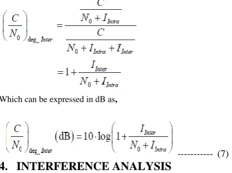
The degradation of caused by the intersystem interference is given by [5] (equation 7)
Which can be expressed in dB as,
--- (7)
4.
INTERFERENCE ANALYSIS
The evaluation of the intersystem interference between the NavIC L5 and Galileo E5a signals
as well as the NavIC L5 and GPS L5 signals will be presented in this section. The degradation of the worst case is computed, which means the maximum received power of the interfering signal and the minimum received power of the desired signal are considered. The Satellite Tool Kit (STK) and MATLAB are used for simulation.
The simulations are divided into the following four scenarios:
1. Galileo E5a signal is interfered by the NavIC L5 signal
2. NavIC L5 signal is interfered by the Galileo E5a signal
3. GPS L5 signal is interfered by the NavIC L5 signal
4. NavIC L5 signal is interfered by the GPS L5 signal
4.1
Simulation Parameters and results
The received power changes during different times and different locations. Received power calculated taking into account constellation and dynamic link budget is given by [5].
--- (8) Where Pj is the emission power at satellite j, Gj is the satellite antenna gain, Adist is the attenuation of the signal due to the
distance between satellite j and user, Aatmis the attenuation of
the signal due to atmospheric loss, Apol is the polarization
mismatch loss, and Gusris the receiver antenna gain.
The expression of calculating Adistis given by equation 9.
--- (9)
Where c is the speed of light, d is the distance between satellite and user, and fc is the centre
Frequency. The attenuation of the signal due to atmospheric loss Aatmis estimated to be 0.5 dB for all services and systems,
the polarization mismatch loss Apolis assumed to be 1.0 dB, the
receiver antenna gain Gusris set to 0 dBic.
The simulation parameters related to simulation are summarised in Table-4 below:
Table 4: Simulation parameters
Parameter
NavIC interferes with GPS
GPS interferes with NavIC
Galileo interferes with NavIC
NavIC interferes with Galileo Simulation
Period 3 days 3 days 3 days 3 days
Elevation
Angle 10 deg 10 deg 10 deg 10 deg
Emission Power (dBW)
NavIC:36.8 GPS:16.14
1
NavIC:35.8 GPS:18.973
Galileo:15. 68 NavIC:35.8
NavIC:36. 8 Galileo:14
.232 Emission
Bandwidth (MHz)
NavIC:24 GPS:30.69
NavIC:24 GPS:30.69
Galileo:90 NavIC:24
Galileo:90 NavIC:24
Front End Bandwidth (MHz)
24.552 24.552 24.552 24.552
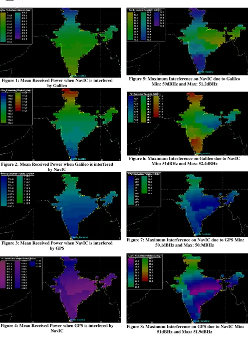
The antenna type has been assumed to be Parabolic and the modulation to be BPSK for all cases. The mean received power for maximum emission power of interfering signal and minimum emission power of derived signal of the systems are shown in figure 1-4.
Figure 5 shows the results of intersystem interference when NavIC is interfered by Galileo. Figure 6 shows the results of intersystem interference when Galileo is interfered by NavIC.
Figure 7 shows the results of intersystem interference when NavIC is interfered by GPS.
Figure 8 shows the results of intersystem interference when GPS is interfered by NavIC.
Figure 1: Mean Received Power when NavIC is interfered by Galileo
Figure 2: Mean Received Power when Galileo is interfered by NavIC
Figure 3: Mean Received Power when NavIC is interfered by GPS
Figure 4: Mean Received Power when GPS is interfered by NavIC
Figure 5: Maximum Interference on NavIC due to Galileo Min: 50dBHz and Max: 51.2dBHz
Figure 6: Maximum Interference on Galileo due to NavIC Min: 51dBHz and Max: 52.4dBHz
Figure 7: Maximum Interference on NavIC due to GPS Min: 50.1dBHz and Max: 50.9dBHz
5.
CONCLUSION
This paper analyses compatibility of NavIC with GPS and Galileo respectively over Indian region. The worst case analysis has been carried out which means intersystem interference will not be larger than the results presented in the paper under the given assumptions. These simulations ensure compatibility between navigation systems. From the simulations, we can conclude that intersystem interference of Galileo due to NavIC is slightly larger than intersystem interference of NavIC due to Galileo in Indian region. Similarly, intersystem interference of GPS due to NavIC is slightly larger than intersystem interference of NavIC due to GPS in Indian region.
6.
REFERENCES
[1] www.ieea.fr
[2] www.navipedia.com
[3] Wallner S, Hein G W, Pany T, Avila-Rodriguez J A, and Posfay A, “Interference computations between GPS and Galileo”, In Proceeding of ION GNSS 2005, pp. 861-876, 2005.
[4] Godet J, “GPS Galileo radio frequency compatibility analysis”, In Proceeding of ION GPS 2000 International Technical Meeting, 2000. Li C X, Liu W M, and Fu Z N, “GPS/TDOA Hybrid Location Algorithm Based on Federal Kalman Filter”, JCIT, Vol. 5, No. 7, pp. 42-48, 2010.
[5] RAN Yi-hang, LIU Yu-qi, HU Xiu-lin, KE Ting, “Interference Analysis of Interplex Modulation in GALILEO E1 Band”, Wireless Communications, Networking and Mobile Computing, 2009. WiCom '09. 5th International Conference , Page(s):1 - 4 ,E-ISBN :978-1-4244-3693-4,Print ISBN: 978-1-4244-3692-7, INSPEC Accession Number: 10952820 .
[6] Klobuchar J (1986), “Design and characteristics of the GPS ionospheric time delay algorithm for single frequency users”, Proceedings of PLANS’86-position location and navigation Symposium, Las Vegas, Nevada.
[7] Evaluation of Intersystem Interference between Compass and Galileo RAN Yi-hang, LIU Yu-qi, HU Xiu-lin, KE Ting Journal of Convergence Information Technology, Volume6, Number 6, June 2011.
[8] Betz J W and Goldstein D B, “Candidate designs for an additional civil signal in GPS spectral bands”, The MITRE Corporation, Bedford, MA, 2002.
[9] Betz J W, “Effect of partial-band interference on receiver estimation of CN0”, The MITRE Corporation, Bedford, MA, 2000.
[10]Hoffmann-Wellenhof, Lichtennegger, Wasle, “GNSS Global Navigation Satellite Systems GPS, GLONASS, Galileo & more”, SpringerWeinNewYork.
[11]John W. Betz, “Binary Offset Carrier Modulations for
Radio navigation”, The MITRE Corporation, Bedford,
Massachusetts Received September 2001; Revised March 2002
[12]Gunter W Hein, Markus Irsinger, Jose Angel Avila radriguez and Thomas Pany, “Performance analysis of L1 Galelio Signals”, Institute of Geodesy and Navigation, University FAF Munich, Germany.
[13]Wei Liu, Yuan Hu, Xingqun Zhan, and Chuanrun Zhai,
“Assessing Radio Frequency Compatibility between
Galileo and Compass”, Defence Science Journal, Vol. 61,
No. 6, November 2011, pp. 545-553, DOI: 10.14429/dsj.61.285.
[14]Hopfield HS (1969), “Two quadratic tropospheric refractivity profile for correcting satellite data”, Journal of Geophysical Research, 74(18):4487-4499.
[15]Dr NBS Srilatha Indira Dutt, Shaik Gowsuddin, “ionosphere Delay Estimation using Klobuchar Algorithm
for single frequency GPS receiver”, IJARCE, Vol2, Issue2
feb2013.
[16]S.Wallner and G.W.Hein, “Interference computation
between GPS and Galileo”, ION,pp.1-15.
[17]Stefan Wallner, Guenter W Hein and Jose- Angel Avila – Rodriguz, “Interference computation between several
GNSS systems”, Institute of Geodesy and Navigation,
University FAF Munich, Germany.
[18]Simon Haykin, “Digital Communications”, John Wiley & Sons (Asia) Pte Ltd.
[19]Oppenheim AV, Schafer RW, Buck JR (1999), “Discrete – time signal processing”, second edition, Prentice Hall, London.
[20]A,Hornbostel, “Propagation problems in satellite
navigation”, DLR, Institute of Communication.
[21]Elliot D. Kaplan, Christopher J. Hegarty, Artech House, “Understanding GPS Principles and Applications”, Artech House Publications.
[22]J.A. Avila-Rodriguez, “On generalized signal waveforms for satellite navigation’’, PhD dissertation University FAF Munich, Neubiberg, Germany, pp. 408, June 2008.
[23]GPS Interface Specification (ICD) , IRN-IS-200F-001: 21st Sept. 2011 .
[24] GLONASS Interface Control Document, version-5.0, 2002.
[25] GALILEO Signal-In-Space, ICD, May 2006.
[26]QZSS Interface Specification (ICD), IS-QZSS, ver 1.4, 28th Feb. 2012.