http://www.sciencepublishinggroup.com/j/com doi: 10.11648/j.com.20170501.11
ISSN: 2328-5966 (Print); ISSN: 2328-5923 (Online)
Handover Delay Estimation Method for IMS-Based Systems
with Heterogeneous Access Networks
Adamu Aminu, Muhammad Lawal
Mathematics and Computer Science Department, Umaru Musa Yar’adua University, Katsina, Nigeria
Email address:
[email protected] (A. Aminu), [email protected] (M. Lawal)
To cite this article:
Adamu Aminu, Muhammad Lawal. Handover Delay Estimation Method for IMS-Based Systems with Heterogeneous Access Networks.
Communications. Vol. 5, No. 1, 2017, pp. 1-7. doi: 10.11648/j.com.20170501.11 Received: March 1, 2017; Accepted: March 23, 2017; Published: April 11, 2017
Abstract:
IP multimedia subsystem (IMS) is an architectural framework designed to merge the Internet and cellular networks, as such users can have access to the current and future services available over the Internet with their mobile devices anytime and virtually everywhere at affordable charges and faster rates, but heterogeneity of access networks in IMS-based systems makes handover process to be a critical issue, especially when moving from one access network to another access network with different technology, hence there is a need to devise a simple approach to estimate handover delay when moving to any access network. This paper proposes a simple method to estimate handover delay for IMS-based systems with heterogeneous access networks. The proposed method can be used to estimate handover delay for current and future access networks, but for illustration purpose, in the paper two access networks were considered, i.e. UMTS and WLAN. Numerical analysis conducted in the paper has shown that handover process to UMTS access network tends to be much longer than that of WLAN access network.Keywords:
IMS, Handover, Access Network, UMTS, WLAN1. Introduction
Provisioning of multiple services such as voice call, Short Message Service and other multimedia data services virtually everywhere is one of the features of mobile networks which has contributed toward their worldwide acceptance and remarkable growth [1]. The first digitally encrypted mobile system was 2G and was designed based on circuit switched technology, where the circuits were optimized to transmit voice and video data [2]. Demand to burst the bandwidth of 2G mobile systems and to offer more services through the mobile technology led to the creation of Third Generation Partnership Project (3GPP) which later facilitated the shift from 2G to 3G cellular systems. The designed 3G system was based on packet switched technology, which is more efficient than circuit switched 2G system. Generally packet switched systems provide IP access to Internet; hence 3G being packet switched in nature transmits IP packets over packet switched network to perform data communications. Subsequently with 3G data transmission became much faster and bandwidth availability for Internet access also increased. With 3G mobile terminals users can download videos, have
access to their emails and enjoy other services similar to that provided over broadband Internet connections such as Integrated Services Digital Line (ISDL), Digital Subscriber Line (DSL). Moreover, 3G services can be enjoyed through various wireless access technologies such as GPRS, CDMA2000, wireless LAN, UMTS, etc. [2, 3]. After successful deployment of 3G mobile networks, the need to increase speed of data transmission still surfaced and other challenges related to 3G systems led to the creation of 4G mobile system. The major task of 4G architecture was system integration, where a unified wireless access technology was to be established through the integration of services offered by the available wireless access technologies; as such 4G aimed at services such as IP telephony, high definition mobile TV, videoconferencing, 3D television, etc. [2, 3].
the Internet (such as WWW services, Email services, VoIP, Instant Messaging, etc.) using a mobile terminal [4]. Conceptually, IMS network architecture can be viewed as the many overlapping wireless Internet access networks (such as WLAN, UMTS, WiMax, etc.) [5]. In this heterogeneous environment, a Mobile Node (MN) is equipped with multiple (often called multi-mode) wireless interfaces to connect to any of the wireless access networks anytime anywhere. Therefore, MN can move from one access network to another and still remain connected [5]. However, providing seamless mobility support when the MN moves from one access network to another access network, has been one of the most challenging problems for the system integration in such environment [5, 6].
Session Initiation Protocol (SIP) was chosen by the 3GPP to serve as a signaling protocol for setting up real-time multimedia sessions in IMS systems [7 - 9]. In IMS heterogeneous environment, the process of transferring MN’s connection from the home access network to visited access network is referred to as handover process [10 - 13]. However, handover process when moving to some access networks may take a long time to be executed, and such long handover delays may not be tolerated by delay sensitive traffics, e.g. voice or video traffic. The handover delay of more than 200 ms makes voice communication very unpleasant [5]. Therefore, it is very vital to have a simple method for the estimation of handover delay when moving to any access network and this would give the hint on whether or not there is need to minimize the handover delay for those access networks which introduce long handover delay.
In this paper a simple method to estimate handover delay for IMS-based systems with heterogeneous access networks was introduced. For illustration purpose we considered IMS-based system with UMTS and WLAN access networks and handover delays for the two networks were estimated, however, the developed method to estimate the handover delay can be applied for any current or future access networks. The rest of this paper is organized as follow: Section II describes the WLAN-UMTS integrated access networks architecture and the mobility issues in such environment. Section III provides the method to estimate handover delay considering UMTS and WLAN as access networks. Numerical analysis was conducted in section IV. Finally section V concludes the paper.
2. System Architecture
For the study, IM-based system consisting of two different access networks, namely, WLAN and UMTS was considered. Logical view of the system architecture is presented in Figure 1. However, mobility in this case can give rise to the following four scenarios: (1) MN moves from UMTS network to WLAN network, (2) MN moves from WLAN network to UMTS network, (3) MN moves from UMTS network to another UMTS network and (4) MN moves from WLAN network to another WLAN network.
However, we are interested on the handover delay incurred
when moving to either of the two networks; to this end let’s briefly describe the procedures involved when handing over services to these two networks.
Figure 1. A system with UMTS and WLAN as access networks.
Table 1. List of acronyms.
Acronym Description
BS Base Station
CN Correspondent Node
GGSN Gateway GPRS Support Node GPRS General Packet Radio Service HSS Home Subscriber Server
I-CSCF Interrogating Call/Session Control Function IMS IP Multimedia Subsystem
MN Mobile Node
P-CSCF Proxy Call/Session Control Function S-CSCF Serving Call/Session Control Function SGSN Serving GPRS Support Node SIP Session Initiation Protocol
UMTS Universal Mobile Telecommunication System
WLAN Wireless LAN
2.1. When Moving to UMTS Network
When MN moves to UMTS network from another network
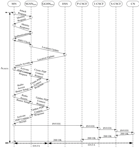
(UMTS or WLAN)it releases the old link and tries to attach
to the target network (in this case UMTS release 5 with GERAN defined as access technology), it does so by firstly making its presence known to UMTS network by sending its International Mobile Subscriber Identifier (IMSI) to Serving
GPRS Support Node (SGSN) for authentication and
attach the acquired IP addresses to its UMTS network interface card (i.e switches to UMTS network interface) and then reestablish the ongoing session with CN (correspondent
node) by sending SIP re-INVITE message to the CN through the SIP proxy servers (Figure 2) [12-14].
Figure 2. Signaling message flow for handover procedure to UMTS network.
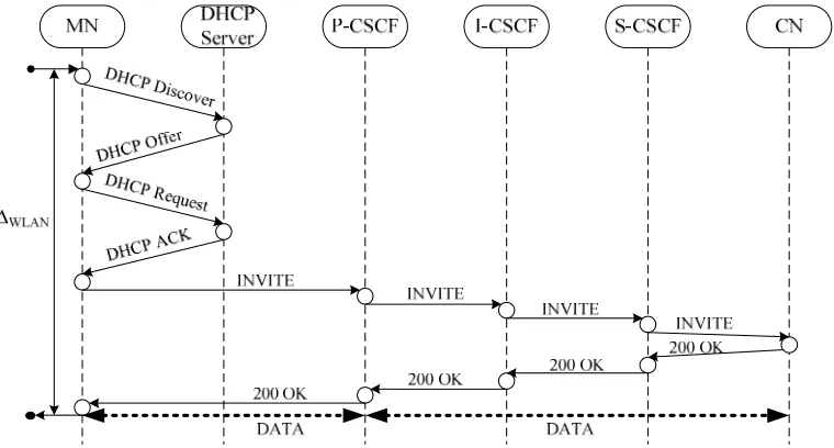
2.2. When Moving to WLAN Network
When MN moves to WLAN network from another network (WLAN or UMTS network), it first releases the old link and tries to attach to the WLAN network. After receiving the characteristics beacons which indicates the presence of WLAN, the MN then broadcasts DHCP DISCOVER message to discover the DHCP server willing to lend it with registration service. The appropriate DHCP server sends out DHCP OFFER message to offer service to the MN. The MN on receiving this OFFER message sends a DHCP REQUEST
Figure 3. Signaling message flow for handover procedure to WLAN.
3. Mathematical Models for Handover
Delay Estimation
Let’s derive expressions to estimate handover delays introduced when moving to UMTS and WLAN access networks.
3.1. Model for UMTS Access Network
Let’s derive an expression to estimate the handover delay for moving to UMTS access network, for that let’s number all the functional entities in the handover procedure depicted in Figure 2 sequentially and subsequently the set of nodes involved in handover to UMTS network would be
{
1, 2,3, 4,5, 6, 7,8}
UMTS =
N
. Assume that all external arrivalsof request at each node is Poisson process with rate λ. The processing rate µi , i=1,⋯,8 at each node is fixed.
Signaling message flow between nodes of the network is described by routing matrix Θ=
( )
θij , i j, ∈NUMTS, wherei i λ ρ
µ
= is the offered load on i-node, i∈NUMTS. Denote by
UMTS
M the set of all the messages required to be processed
to accomplish the total handover procedure to UMTS network, where nm the number of m-message’s transitions
before reaching its final destination node and Lm the size of m-message in bits, m∈MUMTS. Denote also by ∆UMTS the
handover delay when moving to UMTS access network.
Table 2. Routing matrix Θ for UMTS.
0 1 2 3 4 5 6 7 8 ∑
0 0 1 0 0 0 0 0 0 0 1
1 1/7 0 5/7 0 0 1/7 0 0 0 1
2 0 5/8 0 1/4 1/8 0 0 0 0 1
3 0 0 1 0 0 0 0 0 0 1
4 0 0 1 0 0 0 0 0 0 1
0 1 2 3 4 5 6 7 8 ∑
5 0 1/2 0 0 0 0 1/2 0 0 1
6 0 0 0 0 0 1/2 0 1/2 0 1
7 0 0 0 0 0 0 1/2 0 1/2 1
8 0 0 0 0 0 0 0 1 0 1
Proposition 1: Handover delay when moving to UMTS
access network can be estimated by the below expression
1 1
2 3 4 5
1 1 8
6 7
8 2 1 2
7
4 2 2
2 2
2 2 UMTS
UMTS
m m m
n L
µ
µ λ µ λ µ λ µ λ
µ α
µ λ µ λ
−
− −
∈
∆ = + + + +
− − − −
+ + + + ⋅
− −
∑
M(1)
Where 2 3 5 6 7
4
min , , , , ,
4 2 2 2 2
µ µ µ µ
µ
λ< µ
and
α
>
0
[bps] is the data transmission rate, nm the number of m -message’s transitions before reaching its final destination node, Lm the size of m-message in bits.
Proof: Assume 1-node, 8-node to be M M/ / inf type and
the rest of the nodes (2-, 3-, 4-, 5-, 6- and 7- nodes) to be / / 1 / inf
M M type with service discipline FCFS. Handover
procedure when moving to UMTS access network consists of three procedures: GPRS attach procedure, PDP context activation procedure and the session reestablishment procedure using SIP re-INVITE message. Let’s divide the set
UMTS
N into three sets: (1)
{
}
1, 2, 4 UMTS =
N
, (2){
}
1, 2,3 UMTS =
N
and
N
UMTS(3) ={
1,5, 6, 7,8}
. The first set(1)
UMTS
N contain the
nodes that are involved in GPRS attach procedure, second set (2)
UMTS
N contain the nodes that are involved in PDP context
activation procedure and the last set NUMTS(3) contain the
nodes that are involved in session reestablishment procedure. The handover delay can be computed by
UMTS attach PDP re INVITE− UMTS trans−
Where ∆attach is the processing and queuing delay for the
attach procedure, ∆PDP is the processing and queuing delay for the PDP context activation procedure, ∆re INVITE- is the processing and queuing delay for the session reestablishment and ∆UMTS trans- is the total transmission delay to complete the entire handover procedure.
Let’s start with the first component of formula (2) which is
attach
∆ , the set (1)
UMTS
N provides the nodes involved in the
attach procedure.
Then the processing and queuing delay at these nodes to complete the attach procedure would be
1 1 2 4 4 1 3 4
attach µ µ λ µ λ −
∆ = + +
− − (3)
Where min 2, 4
4
µ λ< µ
For the PDP context activation the set (2)
UMTS
N provides the
nodes involved in PDP context activation procedure. Then the processing and queuing delay at these nodes would be
1 1 2 3 4 2 2 4 2
PDP µ µ λ µ λ −
∆ = + +
− − (4)
Where min 2, 3
4 2
µ µ λ<
The set (3)
UMTS
N contains nodes involved in session
reestablishment. Then the processing and queuing delay for the session reestablishment would be
1 1
- 1 8
5 6 7
2 2 2
2
2 2 2
re INVITE µ µ λ µ λ µ λ µ
− −
∆ = + + + +
− − − (5)
The steady-state condition should be
5 6 7
min , ,
2 2 2
µ µ µ λ<
The last component ∆UMTS trans- can be computed by the below expression
1
-UMTS
UMTS trans m m m n L α− ∈ ∆ = ⋅
∑
M, α >0 (6)
Where α [bps] is the data transmission rate, nm the
number of m-message’s transitions before reaching its final destination node and Lm the size of m-message in bits,
UMTS
m∈M . Formula (1) is obtained is by adding formulas
(3) to (6).
3.2. Model for WLAN Access Network
Here the same approach would be used to estimate delay when moving to WLAN access network. Let’s sequentially number all functional entities involved in the handover
procedure in WLAN access network and form a set
{
1, 2,3, 4,5, 6}
WLAN =
N
,N
WLAN =6 . Assume that allexternal arrivals of requests at each node is Poisson process with rate λ. The processing rate µi, i=1,⋯, 6 at each node
is fixed. Signaling message flow between nodes of the
network is described by routing matrix Θ=
( )
θij ,, WLAN
i j∈N , where i
i λ
ρ =µ the offered load on i-node,
WLAN
i∈N . Denote by MWLAN the set of all the messages
required to be processed to accomplish the total handover
procedure to WLAN network, where nm the number of m
-message’s transitions before reaching its final destination node and Lm the size of m-message in bits, m∈MWLAN. Denote also by ∆WLAN the handover delay when moving to WLAN access network.
Table 3. Routing matrix Θ for WLAN.
0 1 2 3 4 5 6 ∑
0 0 1 0 0 0 0 0 1
1 1/4 0 1/2 1/4 0 0 0 1
2 0 1 0 0 0 0 0 1
3 0 1/2 0 0 1/2 0 0 1
4 0 0 0 1/2 0 1/2 0 1
5 0 0 0 0 1/2 0 1/2 1
6 0 0 0 0 0 1 0 1
Proposition 2: Handover delay when moving to WLAN
access network can be estimated by the below expression
1 1
2 3 4
1 1 6 5
2 2 2
4
2 2 2
2 2 WLAN WLAN m m m n L µ µ λ µ λ µ λ µ β µ λ − − − ∈ ∆ = + + + − − − + + + ⋅
−
∑
M(7)
Where min 2, 3, 4, 5
2 2 2 2
µ µ
µ µ
λ<
andβ >0 [bps] is the
data transmission rate, nm the number of m-message’s
transitions before reaching its final destination node, Lm the size of m-message in bits.
Proof: Handover procedure when moving to WLAN
access network consists of two procedures, DHCP registration procedure and the session reestablishment procedure using SIP re-INVITE message. Let’s divide the set
WLAN
N into two sets:
N
WLAN(1) ={ }
1, 2 and{
}
(2)
1,3, 4,5, 6 WLAN =
N
. The first set (1)WLAN
N contains the
nodes that are involved in DHCP registration procedure and
the second set (2)
WLAN
N contains the nodes that are involved in
session reestablishment procedure. The handover delay can be computed by formula below
-
-WLAN DHCP re INVITE WLAN trans
∆ = ∆ + ∆ + ∆ (8)
DHCP registration procedure, ∆re INVITE- is the processing and queuing delay for the session reestablishment and ∆WLAN trans -is the total transm-ission delay to complete the handover procedure.
To derive formula (7) assume that 1-node and 6-node are
/ / inf
M M type and the rest of the node are M M/ / 1 / inf
type with service discipline FCFS. Therefore
1 1
2
2 2
2 DHCP µ µ λ
−
∆ = +
− (9)
Where 2
2
µ λ< .
1 1
- 1 6
3 4 5
2 2 2
2
2 2 2
re INVITE µ µ λ µ λ µ λ µ
− −
∆ = + + + +
− − − (10)
Where min 3, 4, 5
2 2 2
µ µ µ
λ<
The last component ∆WLAN trans− can be computed by the below expression
1
-WLAN
WLAN trans m m m
n L
β− ∈ ∆ = ⋅
∑
M (11)
Where β [bps] is the data transmission rate in WLAN
access network, nm the number of m-message’s transitions
before reaching its final destination node and Lm the size of
m-message in bits, m∈MWLAN. Formula (7) can be obtained
by adding formulas (9), (10) and (11).
4. Numerical Analysis
For Case 1 moving to UMTS access network, it was assumed that the average processing rate at 1-node and 8-node is 0.4 ms, the average processing rate at 2-8-node, 3-8-node and 4-node is 0.5 ms, the average processing rate at 5-node, 6-node and 7-node is 0.4 ms [5]. Assume that the average size of GPRS attach messages is 43 bytes, the average size of PDP Context Activation messages is 573 bytes and average size of SIP messages for session reestablishment is 731 bytes [14]. The channel bandwidth of 128 kbps was considered.
For Case 2 moving to WLAN network, it was assumed that the average processing rate at 1-node and 6-node is 0.4 ms, the average processing rate at 2-node is 0.5 ms, the average processing rate at 3-node, 4-node and 5-node is 0.4 ms [5]. Assume that the average size of DHCP messages is 548 bytes and the average size of SIP messages for session reestablishment is 731 bytes [14]. For the WLAN, a channel with bandwidth 11 Mbps was considered.
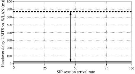
The graphs in Figure 4 and Figure 5 show the handover delay values for moving to UMTS and moving to WLAN respectively. From the graphs it can be observed that the handover delays increases with the increase in SIP session arrival rate, however, as the session arrival requests grows
big for UMTS network, the delay approaches a constant value 675.5 ms whereas when moving to WLAN the delay approaches a constant value of 18.347 ms. The handover delay when moving to UMTS is above the defined tolerable delay for time sensitive traffics which is 200 ms [5].
Figure 4. Handover delay when moving to UMTS.
17.2 17.4 17.6 17.8 18 18.2 18.4
0 25 50 75 100
SIP session arrival rate
Figure 5. Handover delay when moving to WLAN.
The graph in Figure 6 shows the comparison of handover delay when moving to UMTS and when moving to WLAN.
Figure 6. Handover delay UMTS vs. WLAN.
5. Conclusion
devise a simple method to estimate handover delay for any access network and to conduct researches on how to maintain the connectivity of IMS terminals in such a heterogeneous access environment. Thus, in this paper a simple approach to estimate handover delay in IMS-based systems with heterogeneous access networks was proposed. In the paper, however, for demonstration purpose UMTS and WLAN access networks were considered, where formulas were obtained to estimate the handover delay in the two considered access networks, numerical analysis was conducted and results have shown that handover delay to UMTS access network is by far greater than that of WLAN access network, and such long handover delay may not be tolerated by delay sensitive traffics, hence there is a need to devise a technique to minimize handover delay in UMTS access network.
References
[1] S. J. Vivek et al, “Overview on Generations of Network: 1G, 2G, 3G, 4G, 5G,” International Journal of Computer Technology & Applications, Vol. 5 (5), October, 2014, pp. 1789-1794.
[2] S. K. K. Venkata and T. V. Poornima, “A Study of Wireless Mobile Technology”.
[3] International Journal of Advanced Research in Computer Science and Software Engineering, Volume 4, Issue 1, January 2014, pp. 470-474.
[4] A. Clementking and C. V. Jothi, “Study On 4g Communication Architecture Components For Social Networks,” International Journal of Reviews in Computing, 2010, pp. 71-75.
[5] G. Camarillo and M. A. Garcia-Martin, “The 3G IP Multimedia Subsystem (IMS): Merging the Internet and the Cellular Worlds, 2nd ed.,” John Wiley & Sons Ltd, 2006, ISBN: 0-470-01818-6.
[6] N. Banerjee et al., “Analysis of SIP-based mobility
management in 4G wireless networks” Computer Communications vol. 27, 2004, pp. 697–707.
[7] B. Moon, “Fast and Secure Session Mobility in IMS-based Vertical Handover Scenario,” international Journal of Multimedia and Ubiquitous Engineering, Vol. 9, No. 9, 2014, pp. 171-188.
[8] O. Hersent, J. P. Petit and D. Gurle, “The Session Initiation Protocol (SIP),” John Wiley & Sons, Ltd, 2005, ISBN: 0-470-02359-7.
[9] V. S. Rajaram, “Session initiation protocol for wireless channels,” IEEE Transactions on Automatic Control, Dec. 2006.
[10] A. S. Ahson and M. Ilyas, “SIP handbook services, technologies, and security of session initiation protocol,” Taylor & Francis Group, LLC, 2009, ISBN-13: 978-1- 4200-6603-6.
[11] S. Kim, S. K Joo and S. Kyoung-Hee, “Network-based Fast Handover for IMS Applications and Services,” The 11th international conference on advanced communication technology. IEEE Communication Society, Feb. 2009, pp. 1133-1136.
[12] M. Ravichandra, H. N Gowda and U. C. A Kumar, “A Survey on Handovers Literature for Next Generation Wireless Networks” International Journal of Advanced Research in Computer and Communication Engineering, Vol. 2, Issue 12, 2013, pp. 4671-4677.
[13] S. B. Elin and M. Torleiv, “Seamless Handover in Heterogeneous Networks using SIP A Proactive Handover Scheme with the Handover Extension,” International Journal On Advances in Internet Technology, vol. 2, No. 1, 2009, pp. 184-193.
[14] A. Haider and Y. Sufian, “ Soft Handover in 3G/4G Networks Using Multiple Sector Antennas,” International Journal of Engineering and Technology, Vol. 5, No. 1, January, 2015, pp. 10-17.