INNOVATIVE PROCESSES FOR RAPID PROTOTYPING: CASE OF 3D
PRINTER’S DIMENSIONAL QUALIFICATION (DQ)
.
M. B. BELARBI. PhD.1, Prof. M.T. BENABDALLAH. PhD.1,M. G. ABDI. PhD.1 Ecole Nationale Polytechnique of Oran (ENPO), Algeria
Abstract: -This work implements for the first time a dimensional qualification procedure for an open access 3D printer, the authors propose a new methodology to measure the prototype part as a mean to achieve the qualification procedure. Experimental results are compared with the specifications of the designer from a Fused Deposition Modelling (FDM) 3D printing. The quality of the machine recommended by the manufacturer and data are used to obtain its qualification. Then,this work aims to evaluate the quality of the machine through a comparison between the design’s data and the measurements taken from the prototype part (the piece test). So, the results have confirmed and validated the dimensional quality of the machine that was randomly taken from a series of commercial printers.
Keywords: Qualification, 3D, Piece test, prototype part, Quality insurance, Rapid, Prototyping.
1.
Introduction
Rapid prototyping is a technology that allows any manufacturer, artist, researcher, professional designer …to transform digital designs into 3-dimensional solid objects (Figure 1). However, theses prototypes, moulds, machine parts or models or any other product must be qualified and improved by quality insurance. Hence, the ultimate aim of developers and product designers is to come out with better quality products. So, a qualification procedure is needed.
Fig.1. The process ‘FDM’ of prototype in Rapid Prototyping
Fig.2. Cycle of 3D Product Elaboration.
In recent years, the 3D printer has been implemented in many spheres of industry and it becomes possible to Small and Medium Enterprise (SME) to provide a microenvironment research and development as an innovation tool. This tool is sometimes a survival device.The use of Open Access at low cost printers in the field of 'SME ' allows reducing the costs of research and development (R & D) by mobilizing scarce resources especially for the 'START UP', spin
off, and also it is implied for artists, inventors,
craftsmen, etc ...). It is important to note that this paper does not attempt an exhaustive review of
T
he
p
ro
duc
tio
n
Printer
3D
Flow of information
Flow of material Recyclag
The how product
Specific product
Research
Realized Product
Recyclage
T
he
C
o
nc
ept
io
n
Maintenance The identified product
Methods
Fabrication Recyclag
Conception
Planification
Assembly
Sold
Delivered Product The need
Purshase
3D Printer PC
CAD
The real prototype is finished
Innovative Idea
research literature related to the topic of types of 3D printers, its benefits or its future. Rather, the intent is to provide a qualification process of a 3D printer by using a finished prototype part as a sample to test its quality. Further, this latter is more than just the shape of the finished prototype part, it is about a part’s ability to perform the task for which it was designed.
2.
Methodology
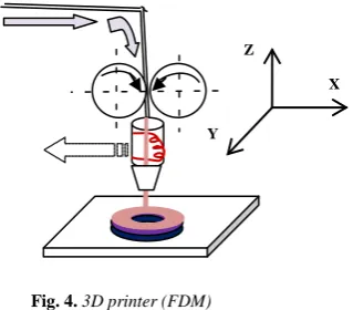
The qualification procedure is done through the realization of prototype parts and then getting the record of their measures to be analyzed and validated with the specifications of the machine. This research focuses on 3D printing using FDM (see Figure 4).
Fig. 4. 3D printer (FDM)
Figures 5.a and 5.b show the material that is going to be used for the qualification procedure which is an
open access at low cost machine.
Fig.5-b. FDM process of 3D printer
In practical term, the metrology allows determining the compliance of the product with the quality claimed
by the manufacturer. This involves the description of the design and the modeling process with an empirical approach. Resources have been designed for the intended control operation to reject or accept the product, according to the general representation of the
new product design process [4]. It is dimensional
qualification of the 3D printer ( ) See Figure 6.
Fig.6. Chart of the process design of new products [4]
3.1
The
Implemented
Qualification
Methodology
The Implemented Qualification Methodology compares the results of the finished prototype parts which are made according to the specifications of the machine data. The metrology analyzes and verifies the results obtained by executing three-dimensional measurement tasks. The author refers to the three approaches shown in the following points, figure 7:
a- The determination of the machine geometry,
b- The achievement of a permutation to separate the
contribution of all fixed defects,
c-
The
realization of a comparison between the valueof measurements made on the finished part and those given by the manufacturer [5].
Z
X
Y
Y
z
x
Fig.5-a. The 3D printer in the realization process of the prototype part (by the FDM).Using creative aid methods
Creative individuals’ resources
Using questionnaires, surveys, Marketing tools and methods.
Marketing individuals’ resources
Using creative methods. Resources experts in the field
( )
Research of ideas
Conflict resolution
Using large series of machines.
Resources engineers and qualified technicians and Operators.
.
Using small series or unitary machines.
Resources engineers and qualified technicians
CAD
Rapid prototyping and testing
Use of computer tools for design and calculation. Resources engineers
Industrialisation Formalization of needs
Fig.7. The verification triangle methods [5]
The quality control does not involve the maximum performance, but compliance with its specified standards. Figure 8 provides a flowchart of the qualification process.
Fig.8.The theoretical description of the qualifying practice
1- Data Catalog
Data collection will be based on the input data available to the user by the manufacturer.
2- Quality insurance
The qualification procedure for Rapid prototyping means a verification of compliance with a standard already adapted in place .
After assessing compliance, we make our judgment on the recognition of the capability of the process of production chain, supplier, component, etc...[6].
3- Working Model
The dimensional measurements are performed in the laboratory of metrology Therefore ambient conditions (baseline T° 20° ± 1° C, relative humidity 55% and pressure at.101325 Pa) should be subject to monitoring devices.
4- Prototype Part
Describe the prototype part with its design and material. It should not require post-processing or manual intervention or the supports to facilitate its control .
5- Measurement
The measurement method of the prototype part is done by a control which allows verifying compliance of the figures contained in the tender specifications (document) of designer (manufacturer). In view of the importance of the measurement errors’ influence on theaccuracy of pieces dimensions; we have chosen the three-dimensional measuring machine.
6-
Results treatment’s methodology
A series of measurements on the test piece will be performed to determine the uncertainty by statistical magnitudes as well as comparing the results with a tolerance interval.
7-
Comparison and validation
It is required to make a comparison between the theory and the results of the various points of the qualification process which was conducted.
8-
Report (end)
The end of the qualification procedure must lead to the systematic generation of a final report which must decide on the acceptance of the FDM printer’s qualification.
3.2 Application
Measures and Dimensions.
Width 480mm
Length 455mm
Including height 455mm
Weight 14kg
Temperature extruded 270 °C (s / type of filament)
Print Volume 230mm x 210mm x 190mm
Maximum print speed 15mm3/ seconde and 50mm/min
Movement X-Y 50 microns,
Minimum print thickness (Z) 100 microns
Materials PLA, ABS, Nylon, Lay Wd &Brick Nozzle diameter 0.4 mm
Filament diameter 3 mm
Steering and connectivity USB and Carte SD
System Compatibility Windows, Mac, Linux
Alimentation 110/220 (V) @ 50/60(Hz) Geometrical
analyses
Incertitudes
Permutation Comparison
1. Data catalog
2. Quatity Insurance
3. Working model
5. Mesurement
8. Report (end)
7. Comparaison
6. Results
Yes
No
Test piece
4.
The developed methodology has been applied on a FDM3D3 machine and has given the following results:
1-
Data catalog
The data is directly taken from the machine’s catalog and available on paper or electronic support, see table 2 (specifications)
Table 2. The 3D printer characteristics [7]
2-
Quality Insurance
The printer under test showed compliance with the characteristics presented by the manufacturer on items 1, 3, 4, 5, 6 and 7, of the present methodology
3-
Working sample
In laboratory, dimensional measurements were identified which are adapted to the ambient conditions of T ° were of 20 ° ± 1 ° C, 53% relative humidity and pressure at.10100 Pa.
4-
prototype part
The prototype part realized on 3D printer with ABS3 base is a chain guard’s crankcase of a sports bike (Figure 9-a and b).
Fig .9-a. Prototype part defined by CAO
Fig .9-b. Prototype part obtained by 3D.
5-
Measurement
The measurement was carried out on all functional dimensions & bulkiness of the test piece.
The measurement ranges are: X=400; Y=350 and Z=300.s
Volumetric accuracy/ functional is: ISO10360/2= (2,8+3L/1000) micron
There are many forms to be controlled, inter alia, the rectitude of the piece contact plane with the motor surface and the distance between the two holes ‘Ø6’ (See figure 10).
Fig.10.Diagram of the piece (crankcase/casing)
The measurements are taken in such a way to avoid the defects of the probe, (see figure 11a).
Fig.11a Prototype part’s Position relative to the MMT probe
Each time, the measurement is done in triple points (Figure11a, 11b).
Z
X
Y
Fig.11b.Prototype part control operation on the MMT.
6-
Treatment of results
The results are obtained by measuring the variances of the finished prototype (test piece) on the three-dimensional measuring machine (MMT) to determine the uncertainty of magnitudes in a statistical manner. It was measured the variances and found 3D printer errors.
7-
Comparaison and validation
A validation of the results is given at the end of this work (see § VI1).
7.1. Results
The determination of uncertainty requires performing measurements series on the same piece and to draw any statistical magnitudes.
7.1.1.
Measures identified gaps and
errors Printer '3D'
The execution of a three-dimensional measurement range encourages performing by the use of prototype parts allowing a correlation matrix establishment This work is carried out under the conditions imposed by the drawing definition (table 4)
Table 4. Correlation matrix reduced for dimensional inspection [8]
Five measures have been identified from the same side on each of the five pieces according to the axes (X, Y and Z).
a. The calculation of the identified dimensions’ terminals [9]:
Upper terminal = Systematic error – Mini error
Lower terminal = Systematic error – Max error
.
Along the X axis:70 ± 0.05 (ṟ) and 70 ± 0.007 (ɱ)
.
Along the Y axis:110 ± 0.045 (ṟ) and 110 ± 0.004 (ɱ)
.
Along the Z axis:25 ± 0.090 (ṟ) and 25 (ɱ)
b. The calculation of the arithmetic mean ( ) of statistical series [10]:
The arithmetic average calculation of statistical series.
Either:
=1n� 𝑥𝑖,
𝑛
𝑖=1
=1n� 𝑦𝑖 𝑎𝑛𝑑 =1n� 𝑧𝑖
𝑛
𝑖=1 𝑛
𝑖=1
Or: n =5 ( )
We conclude that these values are all included as well as their average, within the tolerance interval imposed by the designer, and that following the specification condition ± 0.05 expressed by the following formula: IT = upper tolerance-lower tolerance
IT = 0,05 – (– 0,05) IT = 0,1mm
The measures’ survey is according to X, Y and Z (with n = 5) (Table 5).
Table 5.Measures identified gaps and errors of 3D Machine
The measured deviation or the absolute error is equal to the final:
The final dimension (measured)–the ideal dimension (drawing definition)
PARAMÈTERS PROCESSÉ DIRECTIONS FOR OBDERVATION
LOKED. POSIT.
0/1 REMOVIN. THICKNESS LAYER Z
Dimensions between plane X
& Dimensions between Plan Y ⊗ ⊗ ⊗ Thickness according to X
& thickness according to Y ⊗ ⊗ ⊗ Thickness according to Z
& dimensions between plane Z ⊗ ⊗
Guidance
according to: chosen Cotes Relative error (no unit) Average gap (mm) Plotting of Graphs
X 70±0.05
0,0025 ou 0,25% 0,0035 ou 0,35% 0,0030 ou 0,30% 0,0039 ou 0,39% 0,0031 ou 0,31%
Y 110±0.045
0,0030 ou 0,30% 0,0035 ou 0,35% 0,0032 ou 0,32% 0,0038 ou 0,38% 0,0035 ou 0,35%
Z
25±0.09
0,0025 ou 0,25% 0,0020 ou 0,20% 0,0028 ou 0,28% 0,0025 ou 0,25% 0,0030 ou 0,30%
70,01 70,02 70,03 70,04 70,05
1 2 3 4 5
110,025 110,03 110,035 110,04
1 2 3 4
-0,04 -0,02 0
1 2 3 4 5
X = 41,000 Y = 9,000 Z = 24,975
+0.0044 - 0.0056
70,032Ép. along the X axis
110,034
Ép. along the Y axis
-0, 0256
Ép. along the Z axis
Measured Gap or (absolute error) =
𝑓𝑖𝑛𝑎𝑙𝑟𝑎𝑡𝑖𝑛𝑔 (𝑚𝑒𝑎𝑠𝑢𝑟𝑒𝑑)−Ideal 𝑑𝑖𝑚𝑒𝑛𝑠𝑖𝑜𝑛=
24,9750 – 25 = −𝟎,𝟎𝟐𝟓𝟎(∗) (𝐦𝐦)
Evidence :
Average value retrici. = Error . system.
�∞ (errori+⋯+errorn)
𝑛=1 =
error1 + error2 + error3 + error4 + error5 =
(−(0,025 + 0,02 + 0,028 + 0,025 + 0,03) =
=−0,128/5
average. v. r = −𝟎,𝟎𝟐𝟓𝟔 (mm)
The final graph represents the three selected ratings (according to X, Y and Z) and visualizes the uncertainty and the deviation measures of the five pieces compared to those recommended by the manufacturer (figure 12).
Fig.12. Evolution of the gap 'theory-based measure thickness'
8.
Report (end)
The qualification of the ‘FDM 3D’ printer is verified. The product design is accepted for printing a
multitude of plastic prototypes. The result is then, the acceptance of XXX 3D’ printer’s qualification after verification.
VI. Conclusion
The present work aims to qualify an open source product-design in a laboratory. This qualification is based on the verification of 3D machines’ limits and it integrates the quality aspect on the prototype part
around the identification of the flaws possible sources. The procedure has allowed us to verify the measured
values and compare them with the designer’s data on the drawing. Our aim was first, to examine if the obtained values are in accordance with the tolerance indicated by the designer as well as to conclude whether the FDM process is qualified or not. Further, the obtained results have demonstrated that the methodology developed for qualification is reliable thanks to two simple tests (piece test, machines test) so as to decide on the quality of a low cost 'Open Source' machines.
In perspective, a geometric qualification will be the concern ‘the second "stage"’ of our next research. This work is a foundation stone for a better organization of product quality and opens up the possibility of ensuring low cost Open Access products, download directly open web-sites. This paper puts 3D printing in the field of both ‘quality and reliability’ investigation since printing has entered a historical phase.
References
[1] Joan Horvath Mastering 3D Printing Modeling, Printing, and Prototyping with REPRAP-Style 3D Printers,2014.
[2] Boumediene BELARBI, Qualification of Rapid prototyping process «case of 3D printer », Magister thesis ENPO – Oran, 2013.
[3] The Chandra Source Catalog‘CSC’web/2013.
[4] G. Delaleux, Putting 3D Printing into the Value Stream, 2013. [5] Guillermo CORTES ROBLES, innovation and
knowledge management : A synergy between TRIZ theory and Case-Based Reasoning. Application in process and industrial engineering. 2006.
[6] François HENNEBELLE, Determining the measurement uncertainty on 3D machines, from doctoral thesis, 2007.
[7] Pascal BIGOT CIRA : From «Industrial Instrumentation» of Michel GROUT .
[8](Source:http://fr.wikipedia.org/wiki/RepRap(BCN3D)
[9] [11] Dominique Scaravetti et al, Qualification procedure design of rapid prototyping means, 2001.
[10] (Source, Métrologie Généralités, 38, 01, 1ière G.M.)
[11] (Source : the variance 2011, Glossary of descriptive statistics, (www.economie-cours.fr).
[12] (Source : metrology summary, iut Nancy-Brabois, dpt QLIO in Lunéville-Cyril D).
[13] HERVÉ BONNEFOY, from rapid prototyping to rapid manufacturing , CIPM, university of Reims. march 2003.
[14] GAUTIER MORIN et al, knowledge transfer issue: for outsourcing the design of innovative product PME, 2003. [15] Justin Scott, Project Leader and Additive Manufacturing: Status and Opportunities, 2012.
……….. -0,03
-0,025 -0,02 -0,015 -0,01 -0,005 0 0,005 0,01 0,015 0,02 0,025
1 2 3 4 5
A
v
er
ag
e
g
ap
(
m
m
)
ép.along the X axis
ép.along the Y axis
ép.along the Z axis
Mr Boumédiène Belarbi, was born on 1958, is a had research laboratory
Engineer in Univ. A.B.B. (Tlemcen-Algerie), Master degree in industrial innovation holder, is research PHD student and member of the
IPSIL laboratory at the Ecole Nationale
Polytechnique d’Oran, and he works on R.P & 3D systems qualification and Innovation.
Prof. Tawfik Benabdallah, was born in 1960, is a Doctorate degree Holder, in ThermalMachines & head of the Industrial Products & Systems Innovation Laboratory (IPSIL) at Ecole National Polytechnique of Oran (ENPO-Algeria) and is currently Lecturer at the Mechanical Engineering Dpt. He is involved in several research projects & international cooperation, in innovation & prototyping. Also is member of many international scientific comities, and works in field of energetic systems. E-mail: [email protected]
![Table 4. Correlation matrix reduced for dimensional inspection [8]](https://thumb-us.123doks.com/thumbv2/123dok_us/8577922.1718210/5.595.60.277.410.605/table-correlation-matrix-reduced-dimensional-inspection.webp)
